LV bushing interface design determines whether a low voltage bushing interface reliably carries high current without overheating, degrading, or failing at the terminal connection.
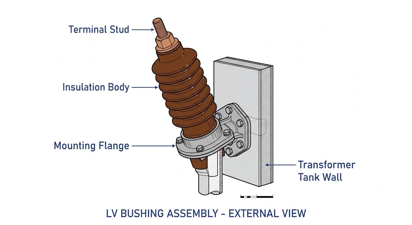
A low voltage bushing interface is the insulated connection point where a transformer’s secondary winding meets external conductors. It combines a terminal stud, an insulating body, and a mounting flange to carry current safely without breakdown, overheating, or mechanical failure — typically rated 600A–5000A across a 1.2 kV–3.0 kV voltage class.
At the upper end of that current range, current density and joint quality dominate design decisions more than voltage insulation does, since the interface must move high current through a comparatively small physical connection point without exceeding the insulation’s thermal limits.
Interface as a System, Not a Part
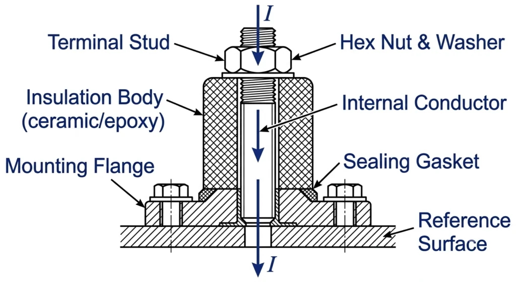
Three zones define the interface’s behavior under load:
The conductive path, where the terminal stud transitions from internal winding lead to external bus or cable connection
The insulation body, which manages dielectric stress and mechanical support — commonly molded from HTN, porous resin, or porcelain
The sealing/mounting interface, which prevents moisture ingress at the tank penetration point
In field terms, engineers rarely think of a bushing failure as “the bushing failed.” More often it’s one of these three zones — usually the conductive path at high current — that degrades first, while the other two remain intact. That distinction matters when diagnosing recurring failures versus isolated defects, and it’s the reason interface design, not just material selection, deserves its own technical treatment separate from a general bushing overview.
This section sets up the structural vocabulary carried through the rest of this discussion — terminal stud, contact interface, insulation transition zone — each covered in design detail below, alongside how ZeeyiElec’s low voltage bushing line applies these principles across current classes.Cross-section of a low voltage bushing interface showing the three functional zones — conductive path, insulation body, and sealing flange — that determine current-carrying performance.
Interface Design Elements That Enable High-Current Transfer
High-current performance at a bushing interface is determined less by voltage rating and more by three coordinated design elements: terminal geometry, contact interface quality, and the insulation-to-conductor transition zone. Each governs a different failure mechanism, so weakness in any one undermines the current-carrying capacity the other two are engineered to support.
Terminal Stud & Conductor Connection Geometry
The terminal stud’s cross-sectional area and thread/bolt interface set the baseline current capacity. Undersized studs or shallow thread engagement create localized hot spots long before the rated current is reached. For interfaces in the 2000A–5000A range, stud diameter and contact surface area typically scale up substantially compared to standard 600A–1200A terminal designs, and connection torque specifications become critical rather than advisory — under-torqued joints are a recurring root cause of field-reported heating complaints on high-current secondary connections.
Contact Interface & Current Density Distribution
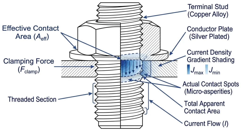
Current density at the stud-to-conductor contact face should remain within a range that keeps localized temperature rise manageable under continuous load. Uneven surface contact — from oxidation, insufficient plating, or misaligned mating surfaces — concentrates current into a smaller effective area than the nominal terminal size suggests.
Current density (J) at the contact face is approximated as J = I / Aeff, where Aeff is the effective contact area rather than the nominal terminal cross-section — a distinction that matters when oxidation or surface pitting reduces true contact area without changing visible dimensions.
Insulation-to-Conductor Transition Zone
This zone manages the dielectric stress gradient as the conductor exits the grounded tank wall through the insulating body. Poor transition geometry — sharp edges, trapped air voids, or inadequate creepage distance — accelerates partial discharge activity over time, even at LV voltage classes where dielectric stress is comparatively low.
In practice, field commissioning teams checking high-current secondary bushings often find that heating issues trace back to the contact interface rather than the insulation itself — a distinction worth confirming with thermal imaging before assuming a bushing needs full replacement. For comparison against medium-voltage interface geometry, see ZeeyiElec’s medium voltage bushing series.Labeled cross-section of the terminal stud and contact interface, illustrating how uneven surface contact concentrates current density and drives localized heating.
[Expert Insight]
Thermal imaging during commissioning catches contact-face hot spots before they show up in resistance testing
Terminal torque should be re-verified after the first load cycle, not just at initial installation
A visibly clean contact surface can still carry reduced effective area if plating is thin or uneven
Material Selection for High-Current LV Bushing Interfaces
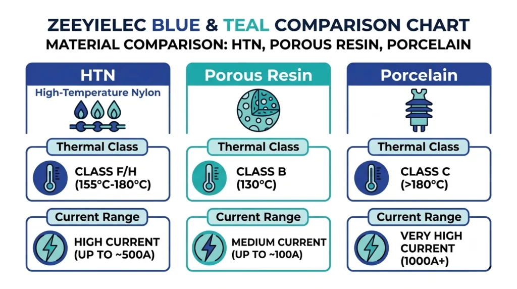
Material choice at the interface directly affects thermal endurance, dimensional stability under load, and long-term contact reliability. The three common options — HTN, porous resin, and porcelain — trade off differently across current class, ambient environment, and mechanical demands.
HTN (High Temperature Nylon)
HTN is favored for high-current LV interfaces where compact terminal design and consistent dimensional tolerance matter. It typically supports continuous operating temperatures in the range of 130°C–150°C, which suits higher current classes where I²R heating at the terminal is a persistent design constraint. Its main limitation is long-term UV and mechanical wear sensitivity in outdoor, unsheltered installations.
Porous Resin
Porous resin bushings offer good dielectric performance and moderate thermal stability, generally suited to mid-range current applications rather than the highest current classes. They are less dimensionally precise than HTN under repeated thermal cycling, which can gradually loosen terminal torque over years of service if not periodically re-checked.
Porcelain
Porcelain remains common where mechanical robustness, cost, and long service history outweigh compact form factor. It performs reliably across a broad temperature range but is heavier and more brittle under mechanical shock — a relevant consideration in transformers with sidewall-mounted, hook-stick-operated accessories nearby.
Material Comparison
Material
Typical Thermal Class
Best Fit
Key Limitation
HTN
~130°C–150°C continuous
High-current, compact terminal designs
UV/mechanical wear outdoors
Porous Resin
Moderate
Mid-range current, general distribution use
Torque drift under thermal cycling
Porcelain
Broad range
Cost-sensitive, mechanically robust applications
Brittle under mechanical shock
Material selection should always be cross-checked against the transformer’s actual current profile rather than chosen by cost alone — a mismatch here is one of the more common root causes traced during field failure diagnosis.
Flat-design comparison of HTN, porous resin, and porcelain bushing interface materials across thermal class, best-fit application, and key limitation.
Thermal Behavior and Current Rating Considerations
Current rating for a low voltage bushing interface is not a fixed number stamped on a datasheet — it is derived from allowable temperature rise under continuous load, ambient conditions, and the thermal class of the surrounding insulation material. Understanding this derivation explains why two bushings with identical physical dimensions can carry different rated currents depending on material and design.
Temperature Rise as the Governing Constraint
The core design constraint is keeping hot-spot temperature at the terminal interface within the insulation material’s continuous thermal rating. For HTN interfaces rated near 130°C–150°C continuous, allowable temperature rise above a typical 40°C ambient leaves a working margin that current rating calculations are built around; exceeding that margin accelerates insulation aging even without immediate failure.
Temperature rise at the contact interface is approximated as ΔT = ΔTambient + I2Rjoint, where Rjoint is the effective contact resistance at the terminal — meaning even small increases in joint resistance from oxidation or under-torqued connections produce disproportionate heating as current climbs toward the upper end of the rated range.
Standards Basis for Temperature Rise Limits
Transformer temperature rise limits — average winding and top-oil rise — are governed by IEC 60076-2, which sets the overall thermal envelope a transformer must operate within. Bushings and other accessories, however, are addressed by their own component standard: IEC 60137 (Insulated bushings for alternating voltages above 1000 V), which IEC 60076-1 explicitly directs designers to consult so that accessory thermal limits don’t restrict the transformer’s rated loading capability. The specific terminal-point temperature rise limit for LV bushing interfaces under sustained high-current load per IEC 60137. For engineers cross-referencing derating tables, IEC 60137 is the appropriate authority reference for this section — https://webstore.iec.ch/publication/1301 (IEC 60137 official page).
Practical Derating Considerations
Ambient temperatures above the standard 40°C reference, enclosure ventilation limits, and duty cycle (continuous versus cyclic loading) all reduce effective current rating below the nameplate figure. Field commissioning teams working in high-ambient regions — coastal substations or poorly ventilated kiosk enclosures, for example — routinely apply derating factors rather than relying on catalog ratings at face value, since a bushing rated for 3000A at 40°C ambient may see meaningfully reduced safe continuous capacity at 55°C ambient without design changes elsewhere in the interface.
This thermal margin is the practical reason interface design and material selection cannot be treated independently from current rating — they are the same engineering decision viewed from different angles.
Field Performance: Contact Resistance and Connection Integrity
Interface design and material selection define theoretical current-carrying capacity; field conditions determine what actually happens over years of service. Contact resistance at the terminal interface is the single most field-relevant parameter, because it degrades gradually and often silently until a thermal event or scheduled inspection reveals it.
What Contact Resistance Looks Like in the Field
Newly installed, correctly torqued LV bushing interfaces typically show contact resistance in the low milliohm range at the terminal joint. Over time — particularly in high-vibration environments like pad-mounted transformers near roadways, or in coastal installations with elevated humidity — that resistance can climb measurably even without a visible fault. Field commissioning teams commonly use micro-ohmmeter testing as part of acceptance checks, and a resistance reading elevated beyond the manufacturer’s baseline by roughly 20%–30% is a common trigger point for re-inspection rather than immediate replacement, since torque re-check often resolves it.
Connection Integrity Under Load Cycling
Distribution transformers rarely run at a flat, constant load. Daily and seasonal load cycling causes repeated thermal expansion and contraction at the terminal joint, and over enough cycles — commonly observed after 3–5 years in high-duty-cycle applications — this can loosen torque on interfaces not designed with sufficient clamping force margin or belleville/spring-loaded hardware to compensate for thermal movement.
One recurring field observation: heating complaints attributed to “bushing failure” during commissioning inspections frequently trace back to torque loss rather than any defect in the bushing itself. Re-torquing to specification and re-testing contact resistance resolves a meaningful share of these cases without part replacement — a distinction worth confirming before escalating to a full accessory swap.
Environmental Factors Worth Field-Checking
Ambient temperature swings and enclosure ventilation
Vibration exposure (roadside, industrial, or vehicle-adjacent installations)
Moisture ingress history at the mounting flange seal
These field realities link the design elements covered earlier to long-term reliability outcomes, setting up the failure-mode discussion below.
[Expert Insight]
A 20–30% rise in contact resistance versus baseline is a practical re-inspection trigger, not an automatic replacement signal
Coastal and high-vibration sites warrant tighter inspection intervals than standard distribution environments
Torque loss and material/design defects present similarly at first — resistance testing distinguishes them faster than visual inspection
Common Interface Design Failure Points
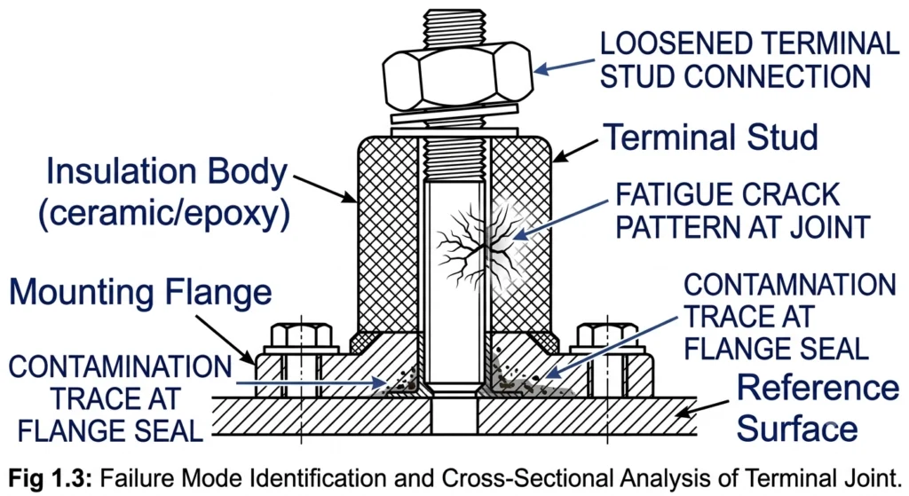
Most LV bushing interface failures in high-current applications trace back to one of three root causes: loose terminal torque, thermal cycling fatigue, or contamination ingress at the interface. Distinguishing between them during field diagnosis determines whether the fix is a re-torque, a component replacement, or an installation-environment change.
Loose Terminal Torque
Under-torqued connections are the most common root cause identified during field failure diagnosis on high-current secondary interfaces. Insufficient clamping force increases contact resistance at the joint, which under continuous load in the 2000A–5000A range can produce localized heating well before any visible discoloration or insulation damage appears. This is typically caught early through periodic micro-ohmmeter testing rather than visual inspection alone, since visible signs often lag the actual resistance increase by months.
Thermal Cycling Fatigue
Repeated expansion and contraction at the terminal joint — driven by daily load variation and seasonal ambient swings — gradually loosens torque on interfaces without sufficient clamping force margin. This mechanism is distinct from a one-time installation defect: it develops progressively, commonly becoming measurable after several years of cyclic high-current service, and is a primary reason interfaces rated for sustained high current benefit from spring-loaded or belleville washer hardware that maintains clamping force through thermal movement.
Contamination Ingress at the Interface
Moisture or particulate ingress at the mounting flange seal or insulation-to-conductor transition zone degrades dielectric performance over time, even though LV bushings operate at comparatively low voltage stress. In coastal or high-humidity installations, this often manifests first as surface tracking or minor corrosion at the contact face rather than a sudden dielectric breakdown — an early warning sign field teams should treat as a maintenance trigger rather than a cosmetic issue.
Diagnostic Priority in the Field
When a heating or performance complaint arises on a high-current LV bushing interface, checking torque and contact resistance first — before assuming material or design failure — resolves a meaningful share of reported cases without part replacement. This diagnostic sequence aligns with ZeeyiElec’s broader field failure diagnosis workflow for transformer and cable accessories.Annotated cross-section highlighting three common LV bushing interface failure indicators — loose terminal torque, thermal cycling fatigue, and contamination ingress.
Selecting the Right LV Bushing Interface for Your Application
Getting LV bushing interface design right at the specification stage — current rating, material, and environment — avoids most of the field issues covered above.
Choosing the right LV bushing interface comes down to matching three parameters to your application: expected continuous current (typically in the 600A–5000A range), ambient/environmental exposure, and material thermal class. High-current applications with limited enclosure ventilation generally favor HTN interfaces for their higher continuous thermal rating, while cost-sensitive or mechanically demanding installations may still justify porcelain despite its bulk.
Before finalizing a spec, cross-check terminal torque hardware and contact interface design against your duty cycle — continuous high-load applications benefit from spring-loaded clamping hardware that resists the torque loss described above. Environmental exposure (coastal, high-vibration, or high-ambient installations) should also factor into material selection rather than being treated as a secondary consideration.
ZeeyiElec’s transformer accessories range covers bushings, tap changers, fuses, and switches across current and voltage classes, with the same engineering-selection support extended to the cable accessories line for projects spanning both transformer and cable interconnection points.
Share your required current rating, ambient conditions, and terminal configuration, and our technical team will confirm the correct interface specification for your project.
Frequently Asked Questions
What current rating can a low voltage bushing interface handle?
LV bushing interfaces typically support current ratings from 600A to over 5000A, depending on terminal size, material class, and conductor cross-section, so the applicable rating should always be matched to the specific transformer’s load profile rather than a generic default.
What voltage class do LV bushings operate in?
Low voltage bushings generally cover the 1.2 kV to 3.0 kV class, positioning them for secondary-side connections on distribution transformers rather than primary high-voltage circuits.
Which material is best for high-current LV bushing interfaces?
HTN and porous resin are commonly favored for high-current applications due to their thermal stability and dimensional consistency, while porcelain remains an option where mechanical robustness and cost are prioritized over compact terminal design; the best choice depends on ambient conditions and expected load cycling.
How does contact resistance affect bushing interface performance?
Elevated contact resistance at the terminal interface increases localized heating under load, and even small increases — often in the low milliohm range — can accelerate thermal degradation if torque or surface preparation is inadequate.
What causes LV bushing interface failures in the field?
Most failures trace back to loose terminal connections, repeated thermal cycling fatigue, or contamination ingress at the insulation-to-conductor transition, with root cause often depending on installation quality as much as component design.
How often should high-current bushing interfaces be inspected?
Inspection intervals vary by duty cycle and environment, but many operators check terminal torque and contact condition during routine transformer maintenance cycles, with more frequent checks warranted in high-vibration or high-contamination settings.
Can LV bushing interfaces be retrofitted for higher current applications?
Retrofitting is possible in some cases where terminal geometry and insulation clearance allow it, but any upgrade should be verified against the transformer’s overall thermal design rather than the bushing interface alone.
yoyo shi
Yoyo Shi writes for ZeeyiElec, focusing on medium-voltage accessories, transformer components, and cable accessory solutions. Her articles cover product applications, technical basics, and sourcing insights for global electrical industry buyers.





 English
 한국어
한국어 العربية
 Español
 हिन्दी
 தமிழ்
தமிழ் Deutsch (Sie)
 Français
 Português do Brasil
 Русский