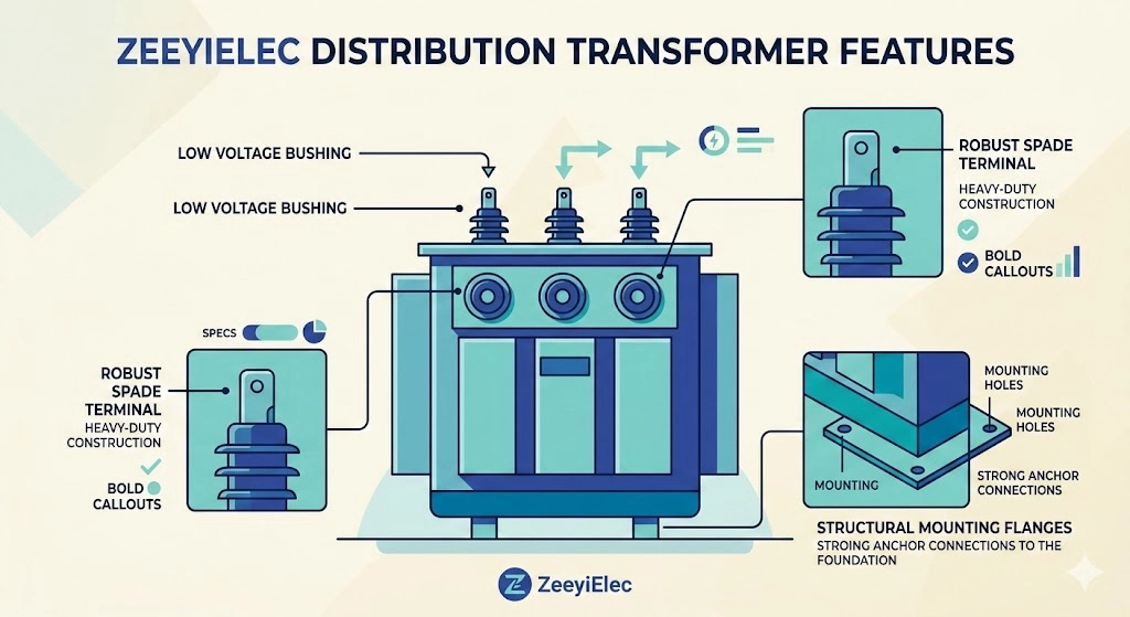
A low voltage transformer bushing is a critical insulated interface mounted on the exterior tank wall of a distribution transformer. Its primary purpose is to provide a secure, electrically isolated pathway for high-current secondary power to exit the sealed, oil-filled enclosure without short-circuiting against the grounded metal casing.
As a fundamental category of transformer accessories, these components operate in a unique physical stress environment. While primary-side medium voltage equipment must control intense electrical fields, low voltage variants are engineered to manage massive thermal dynamics and heavy mechanical loads. Generally designed to conform to structural and electrical guidelines—such as [VERIFY STANDARD: EN 50386 specifications for low-voltage bushings from 1 kV to 3.6 kV]—they execute three core functions within the power distribution system:
High-Capacity Current Transfer
A distribution transformer steps down primary voltage, which inversely drives up the current on the secondary network side. Consequently, low voltage bushings are frequently rated for heavy continuous currents ranging from 600A up to 5000A or higher.
Massive solid copper, brass, or aluminum alloy conductors are necessary to manage this load. Thermal rise within the bushing assembly is primarily driven by I2R losses; meaning that as the secondary current (I) increases, the localized heat generated increases exponentially if the internal contact resistance (R) is not kept exceptionally low across all connection points.
Dielectric Isolation
Although utilized on secondary output circuits (typically operating between 400V and 690V in utility applications), these components are usually insulated for the 1.2 kV to 3.0 kV voltage class to withstand transient overvoltages. The insulating body maintains this necessary dielectric barrier between the energized central conductor and the grounded steel transformer tank, preventing flashovers during switching events or minor lightning surges.
Environmental Sealing
Beyond electrical duties, the bushing acts as a strict environmental barrier for the transformer core. It utilizes compressed nitrile (NBR) or fluoroelastomer gaskets at the tank mounting flange. In field operations, a compromised gasket seal at the low voltage interface is one of the most frequent causes of slow dielectric oil weeping. If left unaddressed, this failing seal allows atmospheric moisture and oxygen ingress, which can rapidly degrade the transformer’s internal paper insulation system based on [NEED AUTHORITY LINK SOURCE] Anchor text: standard testing protocols for transformer bushing oil tightness.
The Physics of Current Transfer: How LV Bushings Function
Understanding how these components operate requires shifting focus from dielectric stress management—the primary concern in medium voltage bushings—to the principles of high-current density management. A distribution transformer stepping down power from 15kV to 400V generates massive secondary currents, often requiring the equipment to continuously carry loads between 1250A and 3150A.
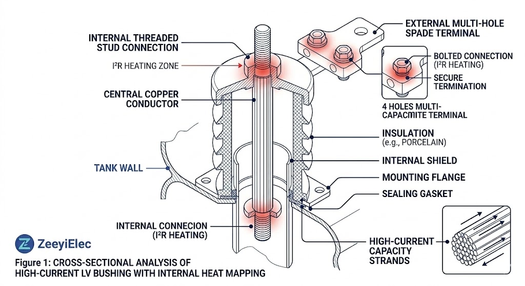
Figure 1:Current transfer path from internal winding leads, through the solid conductor, to the external multi-hole spade terminal, with high-resistance heat zones highlighted.
Internal Winding Connections
The current transfer begins inside the transformer tank. Heavy-gauge secondary winding leads are bolted or brazed directly to the bushing’s internal terminal (often a threaded stud). The efficiency of this joint is critical. The contact resistance at this first mechanical interface must be virtually zero; otherwise, the localized temperature rise will degrade the surrounding transformer oil, generating combustible gases and damaging the internal gasket seals.
The Conductor Pathway
Once past the internal connection, current travels through the core conductor, typically machined from high-conductivity electrolytic copper, extruded brass, or specialized aluminum alloys. The cross-sectional area of this conductor is calculated to maintain a safe current density—usually aiming for roughly 1.5 to 2.5 Amperes per square millimeter (A/mm²) for copper. This precise sizing ensures the thermal losses remain within the operational limits of the surrounding insulation material during peak load cycles.
External Busbar Interface
The final stage of transfer occurs at the external terminal, exposed to the atmosphere. In high-current applications exceeding 1000A, this is rarely a simple threaded stud. Instead, the conductor typically terminates in a large, flat spade connector featuring standardized NEMA drillings (e.g., 4-hole, 6-hole, or 10-hole patterns). Distributing the current across this wide contact patch minimizes localized heating and prevents thermal cycling, which can cause bolted connections to loosen over decades of service.
[Expert Insight]
Contact Resistance is King: A micro-ohm increase in resistance at a 3000A joint generates massive localized heat, rapidly accelerating insulation breakdown and oil degradation.
Surface Preparation: Before mating external copper or aluminum busbars to a bushing spade, the mating surfaces must be heavily wire-brushed and coated with a specialized, antioxidant joint compound to prevent rapid oxidation.
Torque Matters: Proper bolt tension using Belleville washers is critical to maintain constant contact pressure during the inevitable physical expansion and contraction caused by thermal cycling.
Structural Anatomy: Inside a Low Voltage Bushing
A low voltage bushing is a carefully engineered assembly of conductive, insulating, and sealing components designed to address specific thermal, mechanical, and environmental challenges at the transformer tank boundary.
The Central Conductor
The core of the assembly is the solid metal conductor. For lower current applications (e.g., 600A to 1200A), the conductor often utilizes a simple, heavy-duty threaded stud. For high-current applications exceeding 2000A, the external portion is forged or cast into a multi-hole spade terminal. This flattened design provides the immense surface area required to bolt heavy external busbars or multiple secondary cables securely, ensuring the current density remains safely dispersed.
The Insulation Body
Surrounding the conductor is the primary dielectric barrier. The insulation body here is relatively straightforward, as it only needs to withstand up to 3.0 kV. Its primary function is mechanical support and electrical isolation. The body features external sheds (skirts) that increase the surface creepage distance. This specialized geometry prevents tracking currents from crossing the insulator’s surface and causing an external flashover to the grounded tank during wet, icy, or highly contaminated conditions.
Sealing Mechanisms
The structural integrity of the transformer relies heavily on the bushing’s sealing system. Compressed nitrile (NBR) or fluoroelastomer (Viton) gaskets are positioned between the central conductor and the insulator body, and crucially, between the bushing flange and the steel transformer tank wall. Prolonged thermal degradation or physical over-compression of these seals is the leading cause of slow dielectric oil weeping in aging distribution transformers.
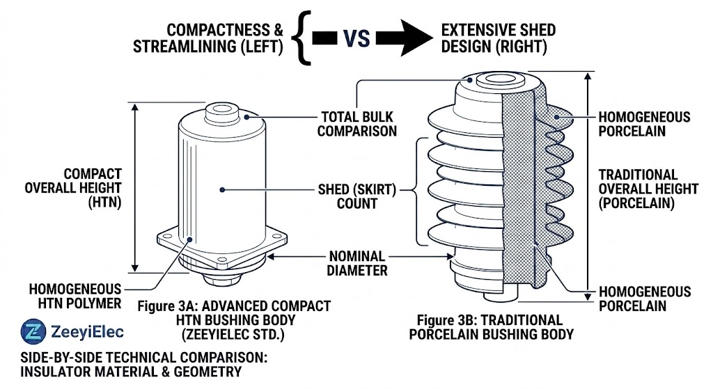
Insulation Materials: HTN, Epoxy, and Porcelain
Selecting the correct insulation material, as detailed in our LV vs MV bushing selection guide, requires balancing dielectric properties against physical durability. The external housing must endure immense mechanical strain from heavy secondary buswork, alongside severe thermal cycling driven by the transformer’s daily load profile.
Figure 2:Comparison of insulator profiles: High Temperature Nylon (HTN) offers superior impact resistance, while traditional porcelain provides unmatched UV stability.
High Temperature Nylon (HTN)
HTN is a modern, high-performance engineering thermoplastic that has rapidly gained market share in distribution transformer manufacturing. Its primary advantage is exceptional impact resistance, which virtually eliminates the risk of cracking during factory assembly, transport, and field installation. From a thermal perspective, specialized HTN compounds maintain their mechanical integrity even when subjected to extreme temperature differentials (ΔT) exceeding 85 °C under peak secondary loads. This resilience makes HTN highly suitable for compact pad-mounted transformers where interior space and heat dissipation are extremely tight.
Epoxy Resin Systems
Cycloaliphatic epoxy resin is cast under deep vacuum to create a completely void-free insulation body yielding a dielectric strength of ≥ 20 kV/mm. Because the liquid resin tightly bonds to the central copper or brass conductor during the curing process, it creates a robust, leak-proof barrier against dielectric oil weeping. Furthermore, cast epoxy provides excellent cantilever strength to support rigid busbar connections without fracturing the flange interface, making it an ideal, heavy-duty selection for heavily loaded industrial switchgear applications.
Traditional Porcelain
Porcelain remains the legacy standard for overhead and outdoor distribution networks worldwide. Typically manufactured from high-alumina ceramics, this material offers unmatched ultraviolet (UV) resistance and long-term chemical stability in highly corrosive, salt-fog, or heavily polluted environments. Governed by long-standing dimensional specifications, such as [VERIFY STANDARD: DIN 42530 guidelines for 1 kV to 3 kV bushing dimensions], porcelain provides excellent tracking resistance. However, its inherent brittleness means installation crews must apply exact torque values to prevent catastrophic shear failure or flange cracking.
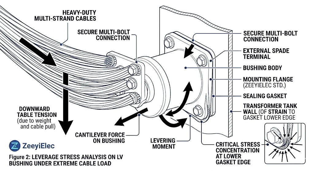
Field Conditions: The Mechanical Reality of LV Connections
While theoretical design focuses on ideal current ratings, the field reality is defined by severe mechanical stress. A 3000A secondary connection on a 2500 kVA distribution transformer must survive decades of physical abuse from external forces, temperature extremes, and structural vibration without compromising the tank’s hermetic seal.
Figure 3:Unsupported heavy secondary cables apply severe downward cantilever load, straining the porcelain/epoxy interface and compressing the mounting gasket.
Managing Cantilever Loads
The most destructive mechanical force applied to a low voltage bushing is cantilever stress. When installation crews attach multiple heavy-gauge secondary cables (properly terminated using industrial cable accessories directly to the spade terminal, the combined weight acts as a massive lever against the insulator body. If these connections are not independently supported by external cable cleats or strut channels, this constant downward pressure can crack porcelain skirts, warp HTN housings, or permanently deform the mounting gasket, leading to catastrophic oil leaks.
Thermal Cycling and Contact Relaxation
Distribution transformers experience continuous load fluctuations, causing the internal conductor and bolted connections to expand and contract daily. This extreme thermal cycling (frequently ΔT > 60 °C) leads to “creep” or contact relaxation. The bolted joint between the bushing spade and the external cable lug slowly loosens, drastically increasing the localized contact resistance (R). According to the I2R principle, this drives temperatures even higher, eventually melting the surrounding insulation or initiating a thermal runaway failure.
Environmental Ingress Protection
The mounting flange is the primary defense against the outside environment. Field experience demonstrates that over-torquing the mounting hardware crushes and ruins the gasket, while under-torquing fails to create a weatherproof seal. Once breached—often accelerated by UV degradation of the exposed gasket edge—rainwater is drawn into the tank during cooling cycles, rapidly degrading the dielectric strength of the insulating oil and threatening the transformer core.
[Expert Insight]
Support the Buswork: Never use the bushing terminal as a structural anchor for heavy cables; independent mechanical bracing is mandatory for long-term reliability.
Thermography is Essential: Routine infrared (IR) scans under peak load conditions reveal failing, high-resistance connections long before they melt the hermetic seal or cause a localized flashover.
Torque Wrench Required: “Hand tight plus a quarter turn” is insufficient; always use a calibrated torque wrench to achieve the precise flange compression values specified by the OEM.
Matching Bushings to Transformer Ratings
Properly selecting a low voltage bushing is a critical step in transformer design and procurement. A mismatched component inevitably leads to overheating, oil leaks, and premature failure in the field. Procurement and engineering teams must evaluate several core parameters before authorizing a purchase order to ensure compatibility with both the transformer rating and the intended operational environment.
Key Selection Criteria
Current Rating: The continuous current capacity must exceed the transformer’s maximum calculated secondary load. For a 2500 kVA, 400V secondary, full-load current approaches 3600A, dictating a bushing rating of 4000A or 5000A to safely accommodate overload conditions, harmonic heating, and future grid expansion.
Voltage Class: While functioning on low voltage circuits, these components must still meet basic impulse levels (BIL). Standard distribution applications usually require a 1.2 kV to 3.0 kV insulation class to survive transient voltage spikes on the secondary network.
Terminal Configuration: The external connection dictates the mechanical design. Lower amperage applications utilize a standard threaded stud, whereas high-current designs (2000A+) mandate a multi-hole spade terminal to distribute the load across multiple cables or rigid busbars safely.
Installation Environment: Traditional porcelain excels in UV-heavy, fully exposed outdoor environments, while HTN or Epoxy Resin systems are preferred for their superior impact resistance in compact, indoor pad-mounted enclosures where physical strikes during maintenance are a risk.
If you are evaluating technical specifications or require OEM/ODM support for an upcoming distribution project, explore the complete range of high-performance Low Voltage Bushings available from ZeeyiElec. Our engineering team provides rapid technical responses and comprehensive export documentation to ensure your procurement process remains on schedule.
Frequently Asked Questions
What is the difference between an LV and MV transformer bushing?
LV bushings primarily handle high continuous current transfer (frequently up to 5000A) at low voltages under 3.0 kV, requiring large diameter conductors but relatively minimal insulation thickness. Conversely, medium voltage (MV) bushings must manage much higher electrical field stress (spanning 15 kV to 35 kV), necessitating complex insulation geometries and extended creepage distances even at lower continuous currents.
Why do low voltage bushings get hot during operation?
They conduct the massive secondary current of the transformer, naturally generating localized heat through I2R losses within the solid conductor mass and at the bolted contact interfaces. Excessive heating—such as exceeding a 65 °C rise over ambient—usually indicates a loose external busbar connection, severe oxidation, or a bushing that is undersized for the current load.
How do you seal a low voltage bushing against oil leaks?
Sealing is achieved using precision-cut nitrile (NBR) or fluoroelastomer (Viton) gaskets compressed strictly between the bushing’s structural flange and the transformer’s steel tank wall. Establishing a reliable hermetic seal requires installation crews to apply exact, manufacturer-specified torque values to ensure adequate compression without distorting the metal flange or tearing the elastomer.
Can you replace an LV bushing without draining the transformer oil?
In the vast majority of liquid-filled distribution transformer designs, replacing a low voltage bushing requires safely lowering the dielectric oil level below the specific mounting hole to prevent spillage. While highly specific externally removable designs exist for some pad-mounted units, standard configurations typically necessitate partial oil draining and breaking the tank’s hermetic seal.
What causes a low voltage bushing to fail?
The most frequent field failure modes include severe thermal degradation from loose external busbar connections, which eventually melts internal sealing gaskets, and mechanical damage to the insulation body from excessive cantilever loads. Slow dielectric oil leaks also inevitably develop due to continuous structural vibration from the transformer core and natural elastomer aging over a 20-to-30-year operational lifespan.
How does cantilever stress affect LV bushings?
Cantilever stress occurs when heavy, unsupported external cables or rigid busbars apply a continuous downward levering force against the bushing’s external terminal. Over time, this mechanical strain transfers directly to the mounting flange, warping the housing, cracking porcelain skirts, and permanently deforming the sealing gasket until a major, system-compromising oil leak occurs.
yoyo shi
Yoyo Shi writes for ZeeyiElec, focusing on medium-voltage accessories, transformer components, and cable accessory solutions. Her articles cover product applications, technical basics, and sourcing insights for global electrical industry buyers.