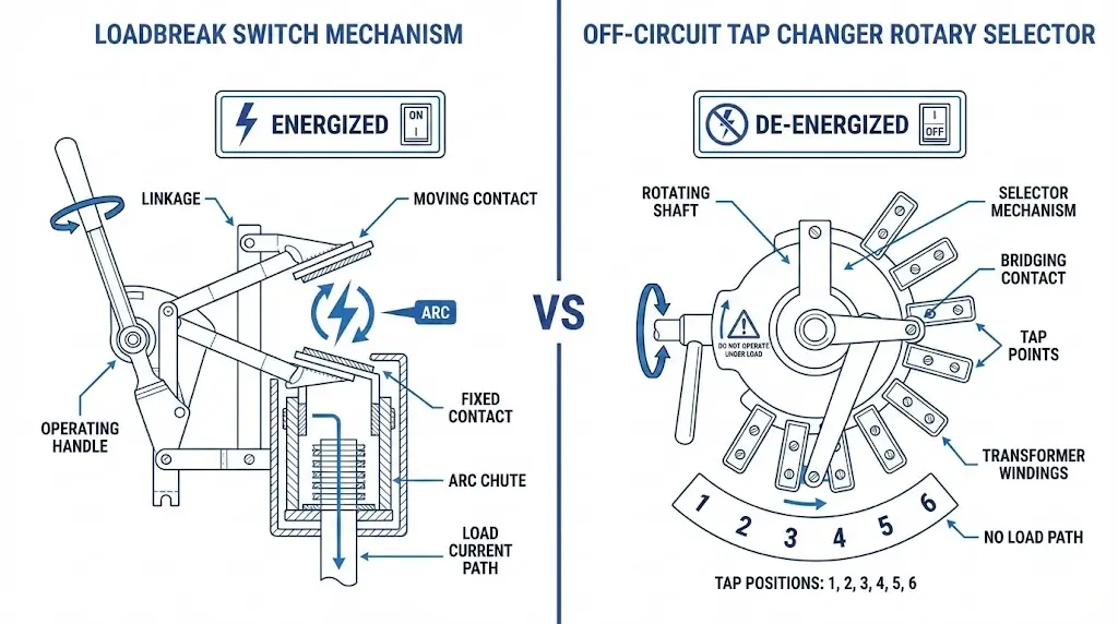
A loadbreak switch interrupts current while the transformer stays energized. An off-circuit tap changer adjusts voltage ratio only after the transformer is de-energized. This single distinction—energized versus de-energized operation—defines the application boundary between these two devices.
Both components appear on distribution transformers. Both involve a switching action. Both mount externally with handles or motor operators. These surface similarities cause confusion among engineers specifying transformer accessories and field personnel operating them.
The confusion carries real consequences. Operating an off-circuit tap changer under load damages contacts and risks internal transformer faults. Specifying a loadbreak switch where voltage adjustment is needed leaves the core problem unsolved. Understanding where each device applies—and where it does not—prevents equipment damage and ensures correct transformer operation.
This article examines the functional boundary between loadbreak switches and off-circuit tap changers. We compare their mechanisms, specifications, and application scenarios, then provide selection guidance for distribution transformer configurations.
How Loadbreak Switches Operate Under Load
A loadbreak switch interrupts load current while energized—a capability that fundamentally distinguishes it from isolation switches and tap changers. The core mechanism involves arc interruption technology that safely extinguishes the electrical arc formed when contacts separate under load conditions.
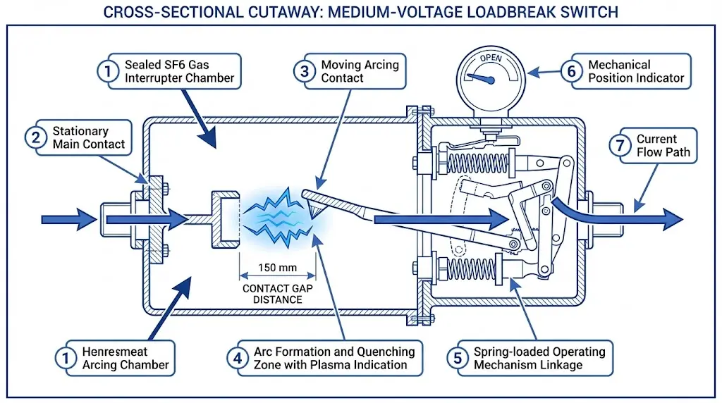
The switching action occurs within an enclosed chamber—typically filled with SF₆ gas, vacuum, or oil—where arc-quenching media rapidly deionize the arc plasma. When contacts separate at rated load current (typically 200–630 A for distribution class units), the arc temperature can momentarily exceed 6,000°C. The interrupting medium absorbs this thermal energy while the arc-extinguishing geometry forces rapid elongation and cooling, achieving extinction within 30–50 milliseconds.
SF₆ designs leverage the gas’s high dielectric strength—approximately 2.5× that of air at atmospheric pressure—enabling rapid recovery of the gap’s insulating capability after current zero crossing. Spring-stored energy mechanisms provide consistent switching speed regardless of manual operator force. This speed independence, requiring contact separation velocity exceeding 1.5 m/s, ensures reliable arc interruption across the rated current range.
Loadbreak switches for distribution transformer applications typically operate at voltage ratings from 15 kV to 38 kV class, with continuous current ratings ranging from 200 A to 900 A. The critical parameter is interrupting capacity—most distribution-class loadbreak switches can safely interrupt currents up to 600 A at rated voltage, though actual fault current interruption requires coordination with upstream protective devices.
According to IEEE C37.30.1, loadbreak switches must demonstrate specific making and breaking capabilities under prescribed test conditions, including verification of arc duration, contact erosion, and dielectric recovery. Field experience across utility distribution systems confirms that properly rated loadbreak switches routinely achieve 1,000+ operations before requiring maintenance inspection.
Figure 1. Loadbreak switch internal structure showing arc-interruption chamber with SF₆ gas volume and spring-operated contact assembly.
The practical significance becomes evident in transformer switching applications: operators can energize or de-energize transformers without de-energizing the entire feeder, enabling load transfer operations and maintenance isolation while maintaining service continuity to adjacent loads.
[Expert Insight: Loadbreak Switch Selection]
Match interrupting rating to actual load current, not just transformer kVA rating—a 500 kVA transformer at 480 V secondary draws only 600 A, but inrush currents reach 8–12× during energization
SF₆ switches offer superior dielectric recovery but require leak monitoring; vacuum interrupters eliminate gas handling but cost more
For pad-mounted applications, verify that the switch rating accounts for loop-feed scenarios where two transformers may back-feed through a single switch
How Off-Circuit Tap Changers Adjust Voltage
Off-circuit tap changers serve a completely different function. Mounted directly on transformer windings, they provide voltage regulation through discrete tap positions—typically ±2 × 2.5% or ±5% adjustment range. These mechanical selector switches require complete de-energization before operation because they lack any arc-interruption capability.
The mechanism connects different winding turns to modify the transformer turns ratio, thereby adjusting secondary voltage output. A rotary or linear selector moves between fixed contact positions, each corresponding to a specific number of winding turns. When the selector moves from one tap to another, it briefly breaks contact with one position before making contact with the next.
Here lies the critical constraint: during that transition, if current flows through the contacts, an arc forms. Unlike loadbreak switches, off-circuit tap changers have no arc-quenching chamber, no SF₆ gas, no vacuum interrupter—nothing to extinguish that arc. The contacts are designed only to carry current, not to break it.
Standard distribution transformer OTCCs provide five positions (two above nominal, two below, plus nominal) with 2.5% voltage change per step. Extended-range designs offer nine positions for ±10% total adjustment. The physical construction involves a rotating drum or sliding contact assembly with silver-plated copper contacts sized for the transformer’s rated current.
Unlike on-load tap changers (OLTCs) found in transmission applications, OCTCs serve cost-sensitive distribution transformers where infrequent voltage adjustments are acceptable. The cost difference is substantial—an OLTC with its diverter switch mechanism, motor drive, and control system can cost 10–15× more than a simple OCTC.
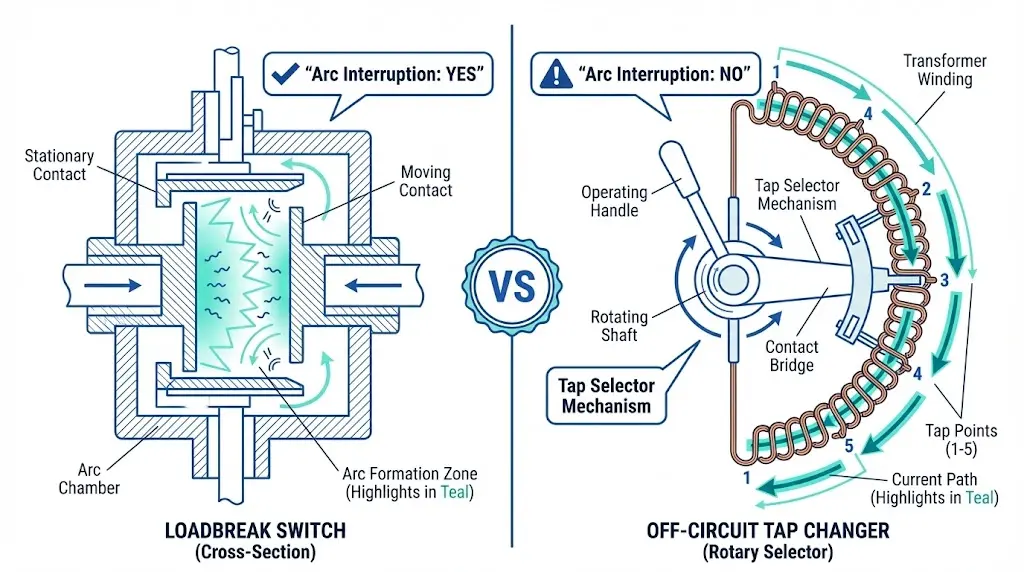
Figure 2. Mechanism comparison showing loadbreak switch arc-interruption chamber (left) versus tap changer selector contacts without arc-quenching capability (right).
Specification Comparison: Ratings and Capabilities
The differences between these devices extend beyond operating philosophy into measurable specifications. The following comparison clarifies what each device can—and cannot—do.
Specification
Loadbreak Switch
Off-Circuit Tap Changer
Primary Function
Load-current interruption + isolation
Voltage ratio adjustment
Operation Condition
Energized (under load)
De-energized only
Arc Interruption Capability
Yes—SF₆, vacuum, or oil chamber
None
Typical Positions
2–3 (open/closed/transfer)
5–33 tap positions
Voltage Adjustment Range
None
±2.5% to ±10% typical
Continuous Current Rating
200 A–900 A
Matches transformer rating
Interrupting Rating
200 A–600 A at voltage class
Not applicable
Typical Mechanical Life
1,000+ load-break operations
2,000+ selector operations
Voltage Classes
15 kV, 25 kV, 38 kV
Integrated with transformer design
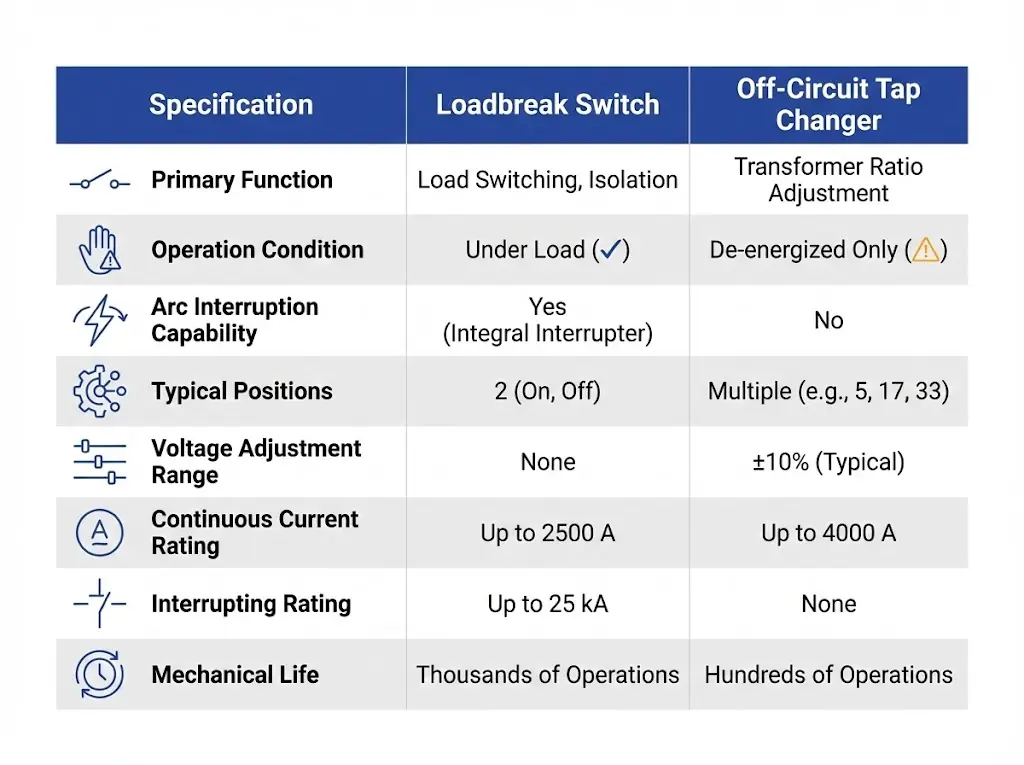
Notice the fundamental asymmetry: loadbreak switches have interrupting ratings while tap changers do not. This single specification difference encapsulates the application boundary. A device with an interrupting rating can break current. A device without one cannot—and must never be asked to try.
The mechanical life figures also differ in meaning. Loadbreak switch operations involve arc formation and quenching, which gradually erodes contacts. Tap changer operations involve only mechanical movement of selector contacts carrying no current. The wear mechanisms differ completely.
Figure 3. Key specification comparison between loadbreak switches (load-current interruption) and off-circuit tap changers (voltage ratio adjustment).
Application Scenarios: When to Use Each Device
Loadbreak Switch Applications
Loadbreak switches solve problems involving current interruption and equipment isolation:
Loop-feed switching: Underground residential distribution (URD) systems typically feed pad-mounted transformers from two directions. Loadbreak switches at each feed point allow operators to transfer load between feeders without interrupting customer service. Open one switch, close the other—the transformer never loses power.
Transformer isolation: When a transformer requires maintenance or testing, the loadbreak switch provides visible isolation. Operators can lock out the switch, apply grounds, and work safely while adjacent transformers on the same feeder remain energized.
Sectionalizing: Following a cable fault, loadbreak switches enable systematic isolation of faulted sections. Operators open switches sequentially to locate the fault, then reconfigure the system to restore service to unfaulted sections.
Emergency load transfer: During feeder overload conditions, loadbreak switches allow rapid load redistribution without dispatching crews to operate upstream breakers.
Off-Circuit Tap Changer Applications
Tap changers solve problems involving voltage magnitude:
Seasonal adjustment: Load patterns change with seasons. Summer air conditioning loads increase voltage drop; winter heating loads may differ. Adjusting taps seasonally—typically during scheduled maintenance windows—keeps secondary voltage within acceptable limits.
Commissioning settings: New transformer installations require tap selection matching actual feeder voltage at the installation location. Feeder voltage varies along its length; transformers near the substation may need different tap settings than those at feeder endpoints.
Long-feeder compensation: Extended distribution runs experience predictable voltage drop. Transformers at the end of long feeders may require permanent tap adjustment to compensate.
Fixed voltage correction: Some installations experience consistent overvoltage or undervoltage due to feeder configuration, capacitor bank locations, or large industrial loads. Tap adjustment provides permanent correction.
The Overlap Zone: Pad-Mounted Transformer Configurations
Many pad-mounted distribution transformers include both devices—a loadbreak switch in the switching compartment and an off-circuit tap changer on the winding. This configuration creates an operational sequence that field personnel must follow precisely.
The correct sequence: open the loadbreak switch first, confirm de-energized status, then adjust the tap changer, then close the loadbreak switch. The loadbreak switch handles the current interruption. The tap changer handles the voltage adjustment. Neither device can perform the other’s function.
In field deployments across more than 150 pad-mounted transformer installations, we’ve observed that operational errors cluster around this sequence. Technicians sometimes adjust tap changers without opening the loadbreak switch first—either due to time pressure, inadequate training, or missing interlocks. The result is arc damage to tap changer contacts, carbonized oil, and potential transformer failure.
Modern transformer designs increasingly incorporate mechanical interlocks that prevent tap changer operation unless the loadbreak switch is open. These interlocks add cost but eliminate a significant failure mode. When specifying new transformer accessories, consider whether interlock provisions are included or available as options.
[Expert Insight: Field Operation Safety]
Always verify de-energized status with a voltage tester before operating tap changers—position indicators can fail or be misread
Document tap positions before and after adjustment; inconsistent records complicate troubleshooting
In cold weather, allow extra time for oil viscosity effects on tap changer mechanism movement
Never force a tap changer handle—binding indicates mechanical problems requiring investigation, not additional force
Failure Modes: What Happens When Boundaries Are Violated
OCTC Operated Under Load
When an off-circuit tap changer operates with current flowing, the sequence unfolds predictably. The selector contact breaks connection with the current tap position. An arc forms. With no quenching mechanism, the arc sustains itself, fed by the load current. Arc temperature exceeds 3,000°C. Contact metal vaporizes. Carbonized particles contaminate the insulating oil.
If the operator continues the tap change, the selector eventually makes contact with the new tap position—but by then, significant damage has occurred. Contact surfaces are eroded and pitted. Oil dielectric strength is degraded. In severe cases, the sustained arc can ignite oil vapors, causing tank pressure rise and potential rupture.
Field inspectors recognize this failure pattern: blackened oil samples, eroded selector contacts, carbon tracking on insulating surfaces. The damage often appears localized to the tap changer area but may extend to adjacent winding insulation.
Prevention Measures
Mechanical interlocks provide the most reliable prevention. A properly designed interlock physically prevents tap changer handle movement unless the loadbreak switch is in the open position. No procedure, no training, no warning label—just mechanical impossibility.
Where interlocks are absent, administrative controls must substitute. Written procedures, lock-out/tag-out requirements, and operator training reduce—but cannot eliminate—the risk of improper operation. Human factors research consistently shows that administrative controls fail at higher rates than engineered controls.
For existing transformer installations lacking interlocks, retrofit kits are available from some manufacturers. The cost of retrofitting is modest compared to transformer replacement following arc damage.
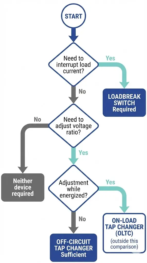
Figure 4. Device selection flowchart based on operational requirements—load current interruption directs to loadbreak switch; de-energized voltage adjustment directs to off-circuit tap changer.
Selecting the Right Device for Your Transformer Configuration
Selection follows from application requirements:
Question 1: Do you need to interrupt load current or isolate the transformer while energized? If yes, specify a loadbreak switch. No other device in this comparison performs this function.
Question 2: Do you need to adjust transformer secondary voltage? If yes, determine adjustment frequency. For quarterly or less frequent adjustments, an off-circuit tap changer is appropriate. For more frequent adjustments—weekly, daily, or automatic—consider an on-load tap changer (outside this comparison’s scope).
Question 3: Do you need both functions? Many applications do. Pad-mounted transformers serving URD systems typically require both a loadbreak switch for loop switching and a tap changer for voltage adjustment. These are separate devices performing separate functions.
Voltage Class Considerations:
15 kV class: Loadbreak switches typically available at 200 A, 400 A, 600 A continuous ratings; tap changers typically ±2 × 2.5%
25 kV class: Loadbreak switches typically 200 A, 400 A; tap changers ±4 × 2.5%
38 kV class: Loadbreak switches typically 200 A; tap changers ±4 × 2.5% or ±5 × 2%
Coordination with protection devices matters. Loadbreak switches must coordinate with upstream fuses or breakers—the loadbreak switch isolates under normal conditions, while upstream devices clear faults. Bay-o-net fuse assemblies provide coordinated transformer protection that works alongside loadbreak switches in pad-mounted configurations.
Source Quality Loadbreak Switches and Tap Changers for Your Application
The application boundary is now clear: loadbreak switches handle energized switching and isolation; off-circuit tap changers handle de-energized voltage adjustment. Many transformer configurations require both devices working in proper sequence.
ZeeyiElec supplies both loadbreak switches and off-circuit tap changers engineered for distribution transformer applications across 15 kV through 38 kV voltage classes. Our loadbreak switches are rated for 200 A–600 A continuous current with interrupting capacities matched to distribution system requirements. Our tap changers provide standard 5-position and extended-range configurations compatible with major transformer manufacturers’ designs.
Contact ZeeyiElec’s technical team to match loadbreak switch and tap changer specifications to your distribution transformer requirements.
Frequently Asked Questions
Q: Can I operate an off-circuit tap changer while the transformer is energized?
A: Operating an OCTC under load causes arc formation between selector contacts, leading to contact erosion, oil contamination, and potential transformer damage—always de-energize completely before changing taps.
Q: What distinguishes an off-circuit tap changer from an on-load tap changer?
A: An OCTC uses simple selector contacts requiring de-energization, while an OLTC incorporates a diverter switch mechanism with arc-interruption capability, allowing tap changes during normal operation at significantly higher cost.
Q: How many switching operations can a loadbreak switch perform before maintenance?
A: Distribution-class loadbreak switches typically achieve 1,000+ load-interrupting operations before requiring contact inspection, though actual life depends on interrupted current magnitude and switching frequency.
Q: Do pad-mounted transformers include both devices?
A: Most pad-mounted distribution transformers incorporate an integral loadbreak switch in the switching compartment and an OCTC on the winding—separate devices requiring sequential operation for safe tap adjustment.
Q: What tap adjustment range is standard for distribution transformers?
A: Most distribution OCTCs provide five positions (±2 × 2.5%) allowing ±5% adjustment, while extended-range designs offer nine positions for ±10% total range from nominal voltage.
Q: Can a loadbreak switch provide voltage adjustment?
A: Loadbreak switches provide only current interruption and isolation—they contain no mechanism for modifying transformer turns ratio and cannot affect output voltage.
Q: When should I consider an on-load tap changer instead of an off-circuit tap changer?
A: If voltage adjustments are needed more than quarterly, or if de-energizing the transformer for each tap change causes unacceptable customer interruptions, the additional cost of an OLTC may be justified by operational benefits.
yoyo shi
Yoyo Shi writes for ZeeyiElec, focusing on medium-voltage accessories, transformer components, and cable accessory solutions. Her articles cover product applications, technical basics, and sourcing insights for global electrical industry buyers.