Introduction: The Physics of the Bushing Well Interface
The connection point between a distribution transformer and its underground primary cable network relies on a specialized, two-part interface: the permanent epoxy well mounted to the transformer tank, and the replaceable . Installing a bushing well insert is not merely a mechanical threading exercise; it is the field assembly of a high-stress dielectric boundary. When a 200A loadbreak elbow connects to this insert, the underlying interface must transfer current flawlessly while actively managing the intense electrical stress fields present at 15kV, 25kV, or 35kV voltage levels, before transferring the load to the network’s .
A bushing well insert serves three simultaneous functions: establishing a corona-free dielectric seal, providing a secure mechanical mounting point for loadbreak accessories, and maintaining a low-resistance current path from the internal transformer winding to the external cable system. If the installation procedure fails to achieve these objectives—often due to contamination, improper lubrication, or incorrect torquing—the consequences are severe. Microscopic air gaps trapped between the epoxy well and the EPDM rubber of the insert will quickly ionize under medium-voltage stress, initiating partial discharge (corona) that silently erodes the insulation materials. Similarly, inadequate metal-to-metal contact at the base thread creates localized heating, leading to thermal runaway and eventual catastrophic failure of the entire connection.
Understanding the physics of this interface is the foundation of a reliable installation. The mating surfaces rely on an interference fit and specific dielectric lubricants to exclude air and moisture completely. Every step in the installation process is designed to eliminate the variables that compromise this critical boundary.
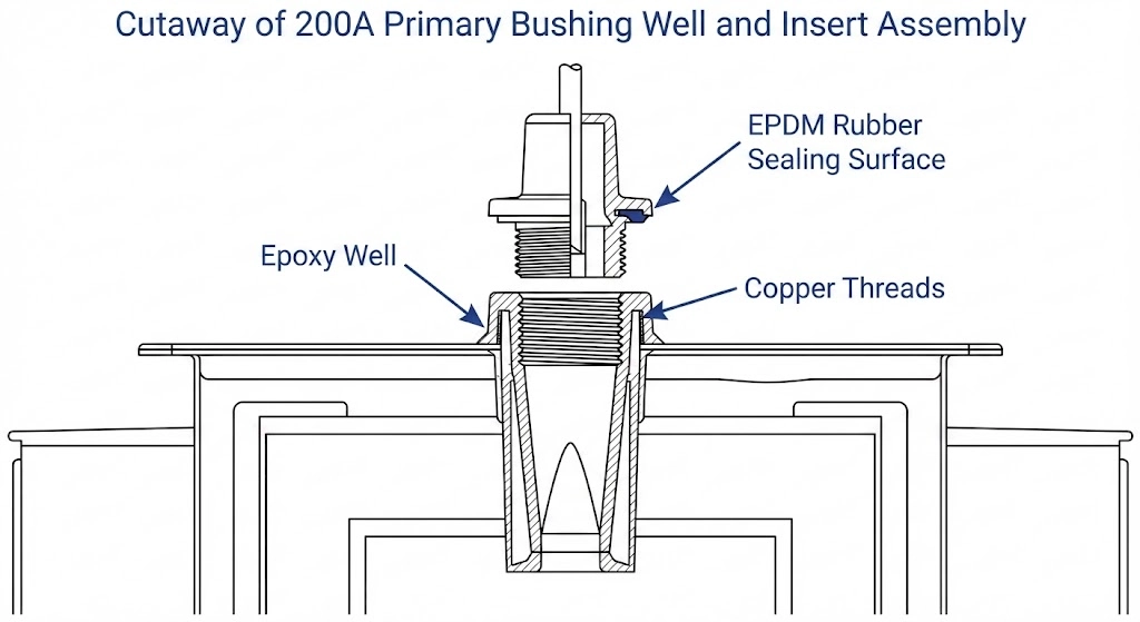
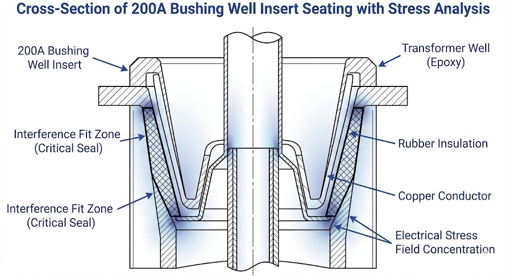
Figure 1: The mechanical interference fit between the epoxy well and EPDM insert actively manages electrical stress fields while preventing moisture ingress.
[Expert Insight: The Realities of Interface Failure]
Over 80% of 200A insert field failures originate from trapped air, moisture, or cross-threading during installation, rather than manufacturing defects.
Dielectric breakdown at this interface often takes 12 to 18 months to manifest as a catastrophic phase-to-ground fault, frequently masking the root cause of the installation error.
Because the interface provides the foundational seal for the transformer tank, a cracked well from over-torquing forces an immediate, costly transformer replacement or shop repair.
Pre-Installation Preparation and Tooling Verification
Before threading the insert into the transformer well, rigorous preparation is required. Field experience consistently demonstrates that a rushed preparation phase directly correlates with cross-threading incidents and long-term dielectric failures. The condition of the well and the quality of the tooling dictate the success of the installation.
Visual Inspection of the Transformer Well
The epoxy surface of the transformer’s bushing well must be perfectly clean and structurally intact. When working in field conditions—especially during retrofits or maintenance on existing distribution transformers—technicians must thoroughly remove dust, moisture, and old grease. Examine the internal copper threads, which are typically standard 3/8″-16 UNC for 200A loadbreak applications. If replacing an old insert, leftover anaerobic thread-locking compound often remains packed inside these threads. Failing to clear this debris will cause the new insert to bind prematurely, giving a false torque reading before the primary electrical contacts have fully mated.
During the visual inspection, meticulously examine the epoxy well surface for any dimensional scoring or deep scratches ≥ 0.5 mm in depth along the mating taper. Scratches exceeding this threshold create microscopic voids that even high-quality dielectric grease cannot reliably bridge, significantly increasing the probability of localized partial discharge. Furthermore, ensure your selected silicone dielectric lubricant is verified for the system’s thermal extremes, typically maintaining its non-curing viscosity across an operating range of −40°C to +130°C.
Required Tooling and Approved Lubricants
Attempting this installation with improvised tools is a primary cause of mechanical damage. Installers must verify their toolkits contain the exact equipment specified for medium-voltage interface work.
First, secure a calibrated torque wrench capable of accurately measuring in the 10 to 20 ft-lbs (13.5 to 27.1 Nm) range, paired with the correct hex-broach drive tool (commonly a 5/16-inch hex shaft). Never use pneumatic or electric impact drivers, as the sudden torque spikes will crack the epoxy well or snap the internal copper stud.
Second, procure lint-free cleaning wipes and an approved, non-residue evaporative solvent. Finally, the installation requires manufacturer-approved silicone dielectric grease. This is a critical selection: using standard petroleum-based greases will chemically attack and swell the EPDM rubber of the insert and mating elbows, leading to rapid insulation degradation within months of energization.
Step-by-Step Installation Procedure
Executing the installation of a 200A bushing well insert demands strict adherence to sequential steps. Field experience shows that deviations—such as improper cleaning or applying the wrong lubrication technique—introduce moisture or air voids that eventually lead to tracking along the epoxy-rubber interface. This procedure aligns with standard utility practices for medium-voltage connections, ensuring a corona-free seal and reliable current transfer.
Step 1: Cleaning the Interfaces
Begin by meticulously cleaning the interior surface of the transformer bushing well and the mating exterior of the new insert. Use only lint-free wipes saturated with an approved, residue-free electrical contact solvent. Wipe in a single, continuous direction to remove all dust, manufacturing oils, and moisture. Never use shop rags or paper towels, as these introduce microscopic fibers that act as tracking paths under high-voltage stress. Allow the solvent to flash off completely before proceeding; trapping solvent beneath the rubber interface will cause rapid insulation breakdown.
Step 2: Applying Dielectric Lubricant
The goal of lubrication is to reduce friction during threading and to completely fill any microscopic air voids between the epoxy well and the EPDM rubber insert. Apply a thin, uniform layer of the manufacturer-supplied silicone dielectric grease to the interior taper of the bushing well and the exterior taper of the insert.
Avoid the common field error of packing the well with excessive grease. Too much lubricant creates a hydraulic lock at the base of the well, preventing the insert from threading fully. A layer approximately 0.5 mm to 1.0 mm thick is sufficient to achieve the required dielectric seal without building excessive fluid pressure during insertion.
Step 3: Threading and Initial Seating
Carefully align the threaded copper stud of the insert with the receptacle in the well. The insert must be perfectly perpendicular to the transformer tank. Begin threading the insert by hand for the first two to three complete rotations. This manual start is critical field practice; it ensures the copper threads engage smoothly and provides immediate tactile feedback if cross-threading begins. If you feel resistance before the third turn, stop immediately, back the insert out, and clean the threads again.
Step 4: Final Torquing Execution
Once the insert is hand-threaded and seated, insert the appropriate hex-broach drive tool into the operating eye or hex receptacle of the insert. Using a calibrated torque wrench, tighten the assembly to the manufacturer’s specified torque. Apply steady, even pressure without jerking the wrench to ensure the copper stud stretches correctly, achieving the required metal-to-metal contact at the base.
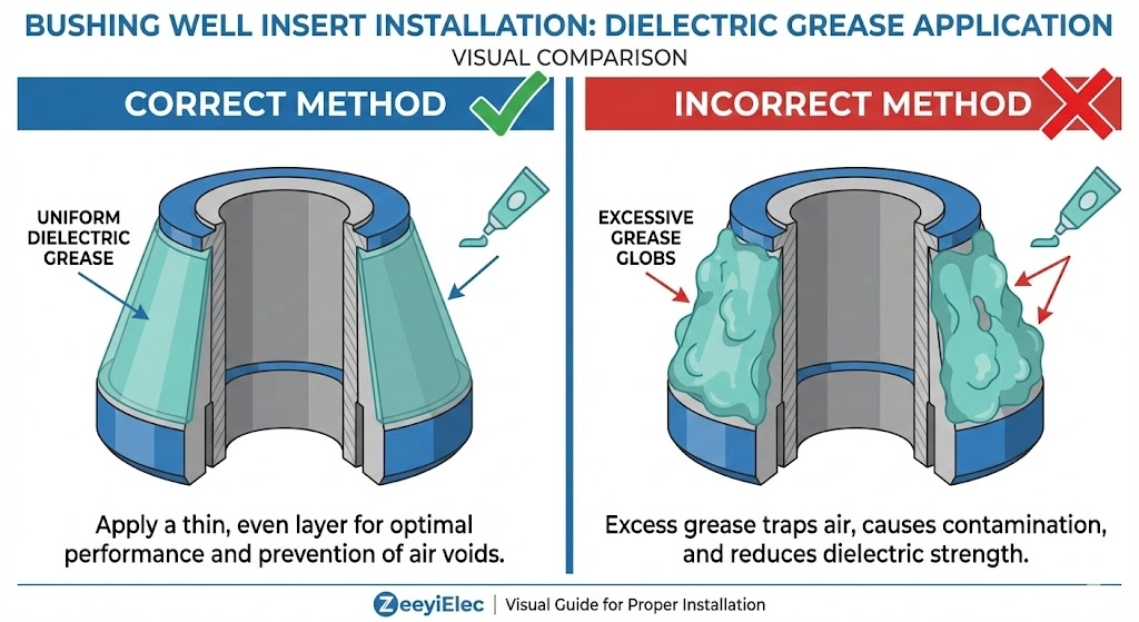
Figure 2: Applying a thin, uniform 0.5 mm to 1.0 mm layer of silicone grease displaces air without causing a hydraulic lock during insertion.
[Expert Insight: Best Practices for Threading]
Always carry a backup insert to the installation site. If an insert is dropped in the dirt or cross-threaded during the initial manual turn, it cannot be cleaned to spec and must be discarded.
When applying dielectric grease, err on the side of a thinner, uniform coat. Excessive hydraulic pressure from too much grease can cause the insert to subtly back out before the final torque locks it in place.
Position your body directly in line with the insert when pushing and turning; off-axis lateral pressure is the primary cause of thread misalignment.
Critical Torquing Specifications and Common Pitfalls
The physical seating of the insert dictates both the dielectric integrity and the current-carrying capacity of the termination. Relying on subjective estimates is the leading cause of premature field failures in 200A loadbreak systems. Securing the interface requires specific mechanical force to stretch the internal copper stud, locking the assembly together while compressing the interface to exclude all air.
Target Torque Parameters and Tooling
For standard 200A and insert assemblies, installers must use a calibrated torque wrench equipped with a 5/16-inch hex-broach tool. The universal target torque for this interface is typically between 10 to 15 ft-lbs (13.5 to 20.3 Nm). Field crews must apply this force using a T-handle torque wrench rather than a standard single-sided ratchet. A single-sided ratchet introduces severe lateral stress during the final tightening phase, which can micro-fracture the epoxy well base before the correct axial torque is ever reached. These mechanical and electrical interface tolerances are strictly governed by industry protocols such as .
Consequences of Under-Torquing
Failing to reach the minimum torque threshold leaves the interface highly vulnerable to thermal and dielectric breakdown.
When an insert is under-torqued, the primary copper contacts fail to achieve the required surface-area engagement. This drastically increases the internal contact resistance, often pushing it beyond the acceptable 50 μΩ to 100 μΩ baseline. During peak distribution load cycles, this elevated resistance causes severe localized heating (excessive ΔT). The continuous thermal expansion and contraction eventually degrade the surrounding EPDM rubber, leading to thermal runaway and complete phase-to-ground faults.
Mechanical Risks of Over-Torquing
Conversely, exceeding 15 ft-lbs (20.3 Nm) introduces severe mechanical risks. Over-torquing is typically the result of using pneumatic tools or uncalibrated wrenches. The internal 3/8″-16 UNC copper threads are designed to yield under extreme tension. Applying 25 ft-lbs or more will stretch the copper beyond its elastic limit, permanently deforming the threads or shearing the stud completely. Even if the stud survives, excessive rotational force can crack the epoxy housing of the transformer well itself, necessitating an expensive transformer tank drain to replace the welded well structure.
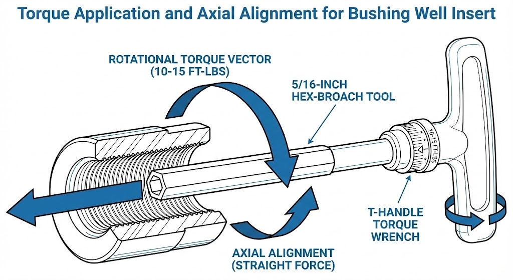
Figure 3: Utilizing a T-handle torque wrench ensures strictly axial force, preventing lateral stress that can fracture the epoxy well housing.
Post-Installation Testing and Verification
Once the torque wrench indicates the correct physical seating of the bushing well insert, the installation is not yet complete. The transition from physical assembly to an electrically viable, corona-free medium-voltage interface requires rigorous post-installation verification before loadbreak elbows are connected or the transformer is re-energized. Bypassing these checks frequently results in catastrophic failure shortly after commissioning.
Visual and Mechanical Validation
Begin with a thorough visual inspection around the circumference of the new bushing well insert where it meets the transformer well face. A proper installation will display zero gaps at the seating collar. The insert’s base flange must sit uniformly against the epoxy well. If an asymmetrical gap exists, it is an immediate indicator of cross-threading or a debris obstruction preventing the internal copper stud from fully seating.
Field crews must then perform a gentle mechanical pull-test. Applying approximately 10 to 15 lbs of lateral force on the insert’s nose will verify the physical integrity of the threaded connection. If the insert exhibits any wobble or rotational play ≥ 1 mm, it must be removed, the threads re-inspected, and the installation procedure repeated from the cleaning phase.
Dielectric Interface Verification
Finally, the exposed interface of the newly installed insert must be prepared to accept the loadbreak elbow. Wipe away any excess dielectric grease that extruded during the torquing process around the base. The outer cone interface must be completely clean and then lightly lubricated with a fresh, microscopic film of approved silicone grease. This final lubrication step ensures that when the loadbreak elbow is pushed onto the insert, the EPDM rubber surfaces glide together smoothly, displacing all air to create the critical 200A dielectric seal.
Sourcing Reliable Bushing Well Inserts for Distribution Projects
The precision required to execute a flawless 200A interface installation means very little if the insert itself lacks dimensional accuracy or reliable dielectric material properties. A successful installation is entirely dependent on selecting high-quality EPDM rubber and precisely machined copper threads that conform to strict industry standards. When sourcing these components for 15kV, 25kV, or 35kV distribution transformers, procurement teams must ensure the accessories are designed for long-term thermal stability and corona-free operation under harsh field conditions.
ZeeyiElec provides engineered solutions for critical distribution accessories, manufacturing bushing well inserts that meet rigorous international project requirements. Our engineering team supports OEM and distributor projects with fast technical matching, complete export documentation, and customized specification support. Whether you are standardizing equipment for utility deployment or securing reliable components for an EPC contract, our precision-manufactured accessories ensure your transformer installations perform safely and reliably for their intended service life. Consult our technical team today for exact specification matching and competitive project quotation.
Frequently Asked Questions
Can I reuse a bushing well insert after it has been removed?
While technically possible if the insert shows zero mechanical wear, industry best practice mandates installing a new insert once removed to guarantee the integrity of the 200A interface and dielectric seal. Micro-tears or thread deformation during extraction significantly increase the risk of partial discharge upon re-energization at 15kV to 35kV levels.
What type of dielectric grease should be used on a 200A insert?
Only use the manufacturer-approved, non-curing silicone dielectric lubricant supplied with or specified for the specific loadbreak accessory. Using standard petroleum-based greases will chemically attack and swell the EPDM rubber components, leading to catastrophic insulation failure within months of field operation.
How tight should a bushing well insert be torqued?
Most 200A bushing well inserts require a seating torque between 10 to 15 ft-lbs (13.5 to 20.3 Nm), but installers must always verify the exact value on the manufacturer’s instruction sheet. Using a calibrated torque wrench with the correct 5/16-inch hex-broach tool is mandatory to prevent under-seating the copper stud or cracking the epoxy well housing.
Why is my bushing well insert cross-threading during installation?
Cross-threading usually occurs when the insert is not perfectly perpendicular to the well during the initial hand-threading phase, or if the internal 3/8″-16 UNC copper threads of the well are contaminated with dirt or old thread-locker. Always start threading by hand for the first two to three full turns before applying any mechanical tooling to ensure proper alignment.
Do I need to de-energize the transformer to replace an insert?
Yes, replacing a bushing well insert requires the distribution transformer to be completely de-energized, isolated, and properly grounded according to strict site safety protocols. While the mating loadbreak elbows can be operated energized under specific controlled conditions, the underlying insert and well assembly form a permanent mechanical connection that cannot be safely unthreaded while live.
What happens if I apply too much silicone lubricant?
Applying excessive dielectric grease creates a hydraulic lock inside the bushing well, preventing the insert from threading fully and achieving the required metal-to-metal contact for current transfer. A thin, uniform layer of approximately 0.5 mm to 1.0 mm is sufficient to displace air and moisture without building up excessive fluid pressure during seating.
yoyo shi
Yoyo Shi writes for ZeeyiElec, focusing on medium-voltage accessories, transformer components, and cable accessory solutions. Her articles cover product applications, technical basics, and sourcing insights for global electrical industry buyers.