Before a transformer arrives on site, the receiving foundation and surrounding infrastructure must be thoroughly verified. Field experience frequently demonstrates that skipping this foundational stage leads to long-term operational issues, ranging from overheating due to poor ventilation to accelerated base corrosion from standing water.
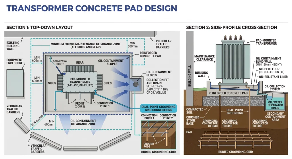
Figure 01:Top-down and side-profile layout of a transformer concrete pad, highlighting minimum maintenance clearances and dual-point grounding grid connections.
Concrete Pad and Clearances
The structural integrity and precise levelness of the concrete pad are critical. A mounting surface that is out of level by more than 1.5 degrees can cause an uneven distribution of dielectric fluid inside the transformer tank. This skewed oil level risks exposing the uppermost sections of the internal windings or the lower leads of the transformer accessories, drastically reducing the system’s dielectric strength and thermal cooling efficiency.
During pre-installation site checks, verify that the surrounding area includes proper grading away from the pad to prevent moisture pooling. Physical clearances must also be verified against project drawings. A minimum clearance of 600 mm (approximately 24 inches) from surrounding walls, fences, or other equipment is generally required. This gap is necessary not only to ensure adequate ambient airflow for the cooling radiators but also to provide safe clearance for personnel conducting future maintenance or taking oil samples.
Grounding System Verification
A robust grounding system is non-negotiable for personnel safety, fault clearing, and surge arrester operation. The site’s grounding grid must be fully installed, backfilled, and tested before the transformer is maneuvered into its final position.
Field engineers must verify the earth grid resistance using a standard fall-of-potential test before equipment placement. For typical medium-voltage distribution substations, the ground grid resistance should consistently measure ≤ 5 Ω. Once the transformer is set, it requires at least two independent connections from the designated ground pads on the tank down to the primary grounding grid. These connections must utilize adequately sized conductors, commonly 4/0 AWG stranded bare copper.
Improperly torqued ground connections or the use of dissimilar metals without approved anti-oxidation compounds will inevitably degrade the connection over time. This degradation increases resistance, prolongs fault clearing times, and puts both the transformer and the wider distribution network at severe risk during a lightning event or ground fault.
[विशेषज्ञ की अंतर्दृष्टि]
Always verify soil resistivity reports match the as-built grounding grid design before concrete is poured.
Account for seasonal water table fluctuations when grading the pad’s drainage slope to prevent baseline corrosion.
Use a calibrated micro-ohmmeter to verify ground connection continuity before energization.
Unloading, Handling, and Internal Inspection
Moving a distribution transformer from a flatbed trailer to its final pad is one of the highest-risk phases of any installation project. The internal core and coil assembly is incredibly heavy and suspended within the fluid-filled tank, making the unit highly susceptible to unseen mechanical damage if handled incorrectly.
Crane and Rigging Best Practices
Proper rigging requires specialized equipment and strict adherence to the manufacturer’s specified center of gravity (COG), which is typically stenciled on the tank exterior. Slings and shackles must be attached exclusively to the engineered lifting lugs. Field crews must never use ट्रांसफॉर्मर सहायक उपकरण, radiators, or bushing turrets as leverage points or temporary lifting aids, as this will fracture the tank welds and compromise the environmental seal.
When attaching the crane’s cables, operators must utilize spreader bars to ensure the lifting slings maintain an angle of ≥ 60° relative to the horizontal plane. Lifting at shallower angles without spreader bars introduces severe inward compressive forces (often exceeding several tons) that can permanently deform the transformer tank walls and damage internal insulation barriers.
Shock Indicator and Impact Assessment
Before the transformer is lifted, the receiving engineer must inspect the shock indicators or electronic impact recorders attached to the unit. These devices track the mechanical forces the transformer experienced during transit across the X, Y, and Z axes.
If the impact recorder registers an acceleration event of ≥ 3G, the installation must be immediately paused. Forces exceeding this threshold strongly suggest that the internal core may have shifted. Even a minor displacement of Δx = 5 mm can compromise the factory-calibrated dielectric clearances between the high-voltage windings and the grounded tank wall.
In such cases, [VERIFY STANDARD: IEEE C57.93] dictates that a comprehensive internal visual inspection through the manhole is required before proceeding. [NEED AUTHORITY LINK SOURCE: IEEE Std C57.93 Guide for Installation of Liquid-Immersed Power Transformers] Field personnel must verify that the core blocking is intact, the tap changer mechanism is not binding, and no internal leads have snapped under tension before finalizing the offloading process.
Transformer Accessory Assembly and Connection
Once the transformer is securely positioned, the installation of external components begins. This phase is governed by strict dielectric and mechanical physics, as every interface point represents a potential vulnerability for oil leakage or moisture ingress if improperly sealed.
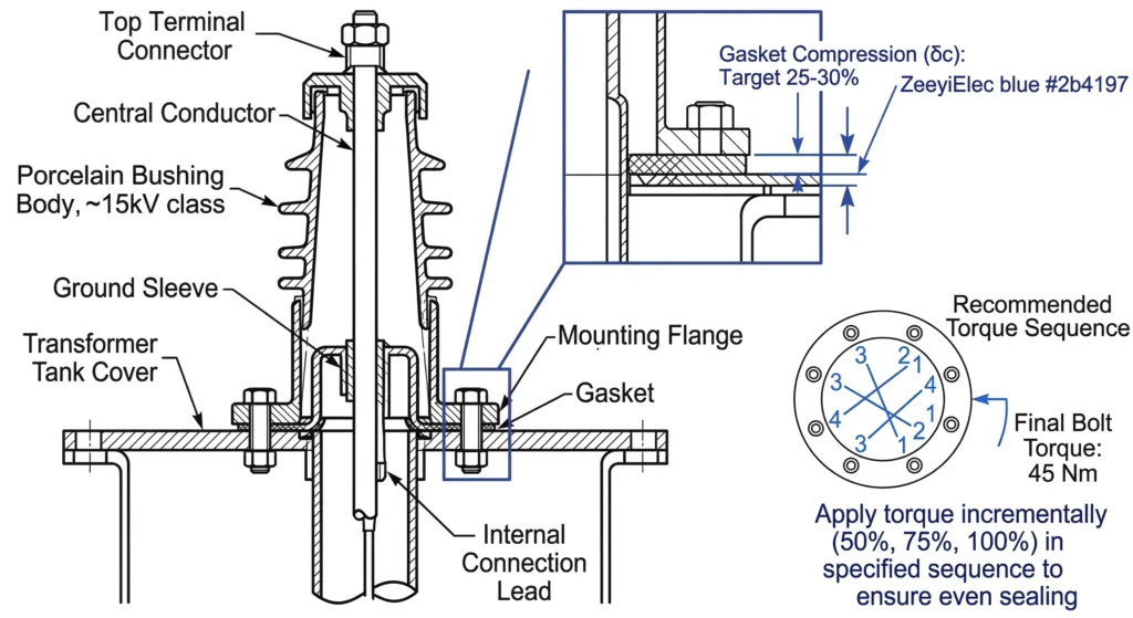
Figure 02:Cross-sectional diagram of medium voltage transformer bushing installation, demonstrating proper gasket compression and torque sequence for hermetic sealing.
Mounting Medium and Low Voltage Bushings
Bushings act as the critical insulated bridge between the internal transformer windings and the external grid. Proper installation requires precise compression of the sealing gaskets—typically Nitrile or Viton rubber—to ensure a lifetime hermetic seal.
When installing मध्यम वोल्टेज ट्रांसफॉर्मर बुशिंग्स rated for 12kV to 52kV, technicians must follow a star-pattern torque sequence per IEC 60137 sealing principles. Uneven tightening can warp the mounting flange or crack the porcelain or epoxy insulation. For निम्न वोल्टेज बुशिंग्स designed to carry massive secondary loads ≥ 5000 A, ensuring uniform gasket compression is vital. These high-current components, often constructed from HTN (High Temperature Nylon) or porous resin, expand and contract significantly under thermal cycling. The mounting hardware is typically torqued to 15 N·m to 25 N·m, compressing the gasket to approximately 65% of its original thickness to maintain seal integrity across a temperature range of -40°C to 105°C.
Installing Protection Fuses and Switches
Transformer protection devices demand equally rigorous handling. Sidewall-mounted Bay-O-Net fuse assemblies provide dead-front safety and hot-stick operable access for field crews. During assembly, the internal O-rings of the fuse holder must be inspected for microscopic debris and lightly coated with an approved dielectric grease. This lubrication prevents the O-ring from rolling or tearing when the fuse holder is locked into the transformer-mounted housing. A compromised O-ring destroys the transformer’s pressure-vacuum seal, allowing insulating oil to escape and atmospheric moisture to enter.
Connecting Cable Terminations
The final mechanical step involves mating the incoming and outgoing power cables to the accessory terminals. Whether utilizing heat shrink or cold shrink technologies, the connection interface must be perfectly clean. Contaminants such as dust or microscopic metal shavings trapped between the cable lug and the bushing terminal will create areas of high electrical stress. Over time, these stress concentrations lead to localized partial discharge, deteriorating the surrounding insulation and eventually causing a catastrophic phase-to-ground fault.
[विशेषज्ञ की अंतर्दृष्टि]
Never reuse nitrile or Viton gaskets once compressed; always install fresh seals during bushing assembly.
Apply a thin film of approved dielectric grease to fuse holder O-rings to prevent tearing during insertion.
Verify accessory torque specs with a calibrated torque wrench, as over-tightening is a leading cause of porcelain fracture.
Oil Filling and Moisture Management
The dielectric fluid within a distribution transformer serves dual purposes: primary electrical insulation and thermal dissipation. Managing the introduction and maintenance of this fluid is fundamentally an exercise in moisture control and vacuum physics. Any breach in handling protocols can severely degrade the internal environment before the unit ever sees operational load.
Dielectric Oil Sampling and Testing
Before energization, the oil must be tested to ensure its dielectric strength has not been compromised by atmospheric moisture during transport, storage, or the final assembly of external components. Water is the primary enemy of transformer insulation; it significantly degrades the breakdown voltage of the oil and exponentially accelerates the thermal aging of the cellulose paper winding insulation.
Field engineers must extract an oil sample from the bottom drain valve, as free water is denser than mineral oil and naturally settles at the base of the tank. For standard medium-voltage distribution transformers, moisture content must be rigidly controlled. A Karl Fischer titration test is typically performed to ensure water content remains ≤ 20 ppm (parts per million). Furthermore, the dielectric breakdown voltage should test at ≥ 30 kV across a standard 2.5 mm gap, in accordance with established IEC 60156 or ASTM D877 test methods.
Settling Time Requirements
Once the transformer is filled or topped off, it absolutely cannot be energized immediately. The fluid filling process inherently introduces microscopic air bubbles into the tank. If subjected to high voltage, these air pockets act as weak voids with a much lower dielectric strength than the surrounding oil. This disparity triggers localized partial discharge that can quickly cascade into a full phase-to-ground dielectric failure.
A mandatory settling period is required to allow entrained gas bubbles to migrate upward and escape to the surface. For typical distribution units < 2500 kVA, a minimum settling time of 12 to 24 hours is standard industry practice. However, field installation crews must closely monitor environmental variables. If ambient temperatures drop below 10°C, the increased kinematic viscosity of the oil severely impedes bubble migration. In these cold-weather scenarios, the settling period must be extended to at least 48 hours to guarantee that the dielectric medium is completely continuous and void-free before the system is energized.
Pre-Energization Testing and Commissioning Protocols
Before applying grid voltage, field crews must execute a rigorous sequence of electrical tests. In practical site conditions, these tests serve as the final diagnostic checkpoint to verify that no internal components shifted during transit and that all internal connections are secure. Skipping these steps or misinterpreting the field data often leads to catastrophic failures the moment the breaker is closed.
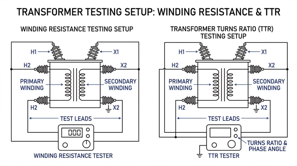
Figure 03:Schematic representation of transformer winding resistance and Transformer Turns Ratio (TTR) testing setup with primary and secondary bushing connections.
Insulation Resistance (Megger) Testing
Insulation resistance testing, commonly referred to as Megger testing, verifies the dielectric integrity between the internal windings and the grounded tank. For a standard medium-voltage distribution transformer, technicians typically apply a 5000 V DC test voltage for one minute. A baseline field rule dictates an acceptable minimum of 1 MΩ per 1000 V of operating voltage, plus an additional 1 MΩ. However, field experience shows that raw readings are completely unreliable without temperature correction. A seemingly healthy reading of 3000 MΩ taken at 10°C might drop to a failing grade when mathematically corrected to the standard 20°C baseline. Inexperienced testing crews frequently fail to record the top oil temperature during this test, leading to false-positive passes and hidden reliability risks.
Transformer Turns Ratio (TTR) and Vector Group
The TTR test confirms that the ratio of primary to secondary turns matches the manufacturer’s nameplate specifications. This diagnostic step proves that no adjacent winding layers were shorted together by mechanical shocks during transport. According to standard commissioning protocols, the measured ratio must fall within a ±0.5% tolerance of the calculated nameplate ratio across all three phases. Deviations beyond this limit, particularly any variance ≥ 1.0%, strongly indicate internal core damage, snapped leads, or a mechanical failure within the tap changer contact assembly.
Setting the Off-Circuit Tap Changer
The final configuration step before equipment lock-out is adjusting the सर्किट से बाहर का टैप चेंजर. This mechanical device must be set to match the specific voltage actively delivered by the local utility grid, which rarely aligns perfectly with the transformer’s nominal rating. Field engineers must measure the actual incoming supply voltage and lock the tap position into the corresponding setting to ensure the secondary output voltage remains stable for downstream loads. As the name implies, this operation is strictly for de-energized adjustment; the operating handle must be padlocked immediately after setting to prevent accidental operation under load, which would destroy the contacts.
Energization, Monitoring, and Final Documentation
The moment of energization represents the ultimate test of all prior installation and commissioning efforts. Field protocols dictate a strict, phased approach to safely introduce the transformer to grid voltage, ensuring that any latent defects are identified before catastrophic damage occurs.
The Energization Sequence
Initially, the transformer must be energized with no secondary load connected. This “no-load soak” period typically lasts for a minimum of 24 hours. During this phase, field engineers monitor the unit for immediate protective relay operations or sudden gas accumulations in the Buchholz relay (if equipped), which would indicate a gross internal fault missed during earlier diagnostic testing. Once the soak period is successfully completed, the load is introduced incrementally—often starting at 25% of nominal capacity and gradually scaling up to 80% or 100% over several hours.
Post-Energization Thermal and Acoustic Checks
Immediately following energization, crews must perform rigorous acoustic inspections. A healthy transformer emits a steady, uniform 50 Hz or 60 Hz hum. Sharp, intermittent crackling noises often indicate internal partial discharge or corona, while a loud, localized buzzing points to loose core laminations or a vibrating transformer accessory. Simultaneously, infrared thermal scanning is mandatory. Technicians must scan all primary and secondary bushing connections, looking for hot spots where the temperature differential (ΔT) exceeds 10°C above the ambient tank temperature. Such anomalies highlight high-resistance connections that require immediate de-energization and re-torquing.
Ready to ensure your next distribution project energizes without costly delays? Contact ZeeyiElec today to share your site specifications, and our engineering team will provide a complete, standard-compliant transformer and cable accessory package tailored perfectly to your application.
अक्सर पूछे जाने वाले प्रश्न
How long must transformer oil settle before energization?
Usually, the oil requires 12 to 24 hours of settling time, depending on the transformer size and fluid volume, to allow entrained air bubbles to escape. Cold weather conditions below 10°C increase oil viscosity and may extend this requirement to 48 hours to ensure full dielectric strength.
What is an acceptable insulation resistance value for a medium-voltage transformer?
A general field baseline is 1 MΩ per 1000 V of operating voltage plus 1 MΩ, resulting in typical readings between 1000 MΩ and 5000 MΩ for MV units. These values are highly temperature-dependent and must be mathematically corrected to a 20°C baseline for accurate assessment.
Can an off-circuit tap changer be adjusted while the transformer is energized?
No, operating an off-circuit tap changer under load will cause severe arcing and catastrophic internal damage. The transformer must be completely de-energized and locked out before any mechanical tap position changes are made.
What should the initial impact recorder reading be upon transformer delivery?
Impact recorders should generally show less than 2G to 3G of shock in any axis, depending on the manufacturer’s specific shipping tolerances. Readings ≥ 3G require a comprehensive internal visual inspection for core shifting or accessory damage before the unit is accepted on site.
Why is a Transformer Turns Ratio (TTR) test necessary during commissioning?
The TTR test confirms that the primary and secondary coils have the correct ratio, typically within a ±0.5% tolerance of the nameplate design. It ensures no shorted turns occurred during transit and validates that the tap contacts are fully engaged across all phases.
At what temperature should transformer commissioning tests be performed?
Testing is ideally conducted when the transformer oil is between 10°C and 40°C, closely matching ambient site conditions. Extreme cold can mask moisture issues within the tank, while high temperatures require significant correction factors for accurate insulation resistance data.
Should cable accessories be tested before transformer energization?
Yes, all केबल सहायक उपकरण—including cold shrink and heat shrink terminations—must undergo VLF (Very Low Frequency) testing prior to energization. This verifies that the field installation process did not introduce microscopic voids or contamination that could lead to immediate partial discharge.
योयो शी
योयो शी ZeeyiElec के लिए लिखती हैं, जहाँ उनका ध्यान मध्यम-वोल्टेज सहायक उपकरणों, ट्रांसफॉर्मर घटकों और केबल सहायक समाधानों पर केंद्रित है। उनके लेख उत्पाद अनुप्रयोगों, तकनीकी मूल बातों और वैश्विक विद्युत उद्योग के खरीदारों के लिए आपूर्ति संबंधी अंतर्दृष्टि को कवर करते हैं।.