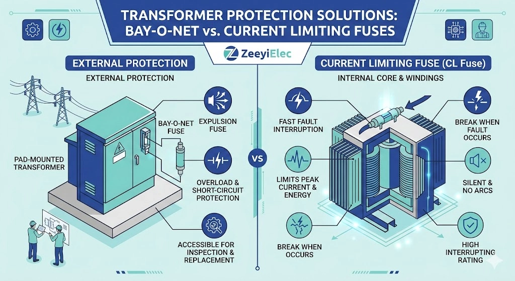
The Foundation of Two-Stage Transformer Protection
Two-stage transformer protection is a coordinated electrical defense strategy that utilizes an expulsion fuse (such as a Bay-O-Net assembly) connected in series with a partial-range current limiting fuse. The expulsion fuse is calibrated to clear low-to-moderate secondary faults and thermal overloads, while the current limiting fuse operates exclusively to truncate severe, high-magnitude primary faults before they can cause a structural rupture of the equipment.
निर्दिष्ट करते समय ट्रांसफॉर्मर सहायक उपकरण for medium-voltage distribution networks—often alongside केबल सहायक उपकरण in comprehensive procurement packages—engineers must account for a vast and punishing fault current spectrum. A single fuse technology cannot safely and economically clear every type of electrical anomaly across this entire range. This physical and thermal limitation necessitates a coordinated, dual-fuse logic.
To understand why this approach is the industry standard for pad-mounted and pole-mounted oil-filled transformers, the fault spectrum must be categorized into two distinct operational zones.
Zone 1: Low-Magnitude Faults and Overloads
These anomalies typically originate on the secondary (low-voltage) side of the transformer. They encompass prolonged secondary overloads, secondary short circuits, and high-impedance internal winding faults. In these scenarios, the fault current rises above normal load parameters but remains relatively restricted—often ranging from 100 A to approximately 3,000 A, depending heavily on the system impedance and the transformer’s kVA rating. The primary engineering objective in this zone is to interrupt the circuit cleanly while avoiding nuisance tripping during acceptable transient events, such as cold-load pickup or transformer magnetizing inrush currents.
Zone 2: High-Magnitude Bolted Faults
These are severe electrical events, typically involving a low-impedance short circuit on the primary side or a massive internal dielectric failure within the transformer’s core and coil assembly. Available fault currents in this zone spike astronomically.
Depending on the utility grid’s stiffness, a bolted fault can deliver asymmetrical currents ≥ 50,000 A within the first ½ cycle (roughly 8.33 milliseconds at a 60 Hz system frequency).
At these extreme magnitudes, explosive mechanical forces and severe thermal stresses threaten to violently rupture the transformer tank, turning a localized electrical failure into a major environmental and operational safety hazard. [NEED AUTHORITY LINK SOURCE: IEEE Std C37.47 distribution fuse application guidelines]
Coordination logic effectively bridges these two zones. By placing two specialized devices in series, network designers ensure that a slow-acting, low-current melting element responds to gradual thermal overloads, while a highly reactive, energy-absorbing element stands ready to instantly truncate massive short-circuit currents.
Physical Mechanisms: How Each Fuse Interrupts Faults
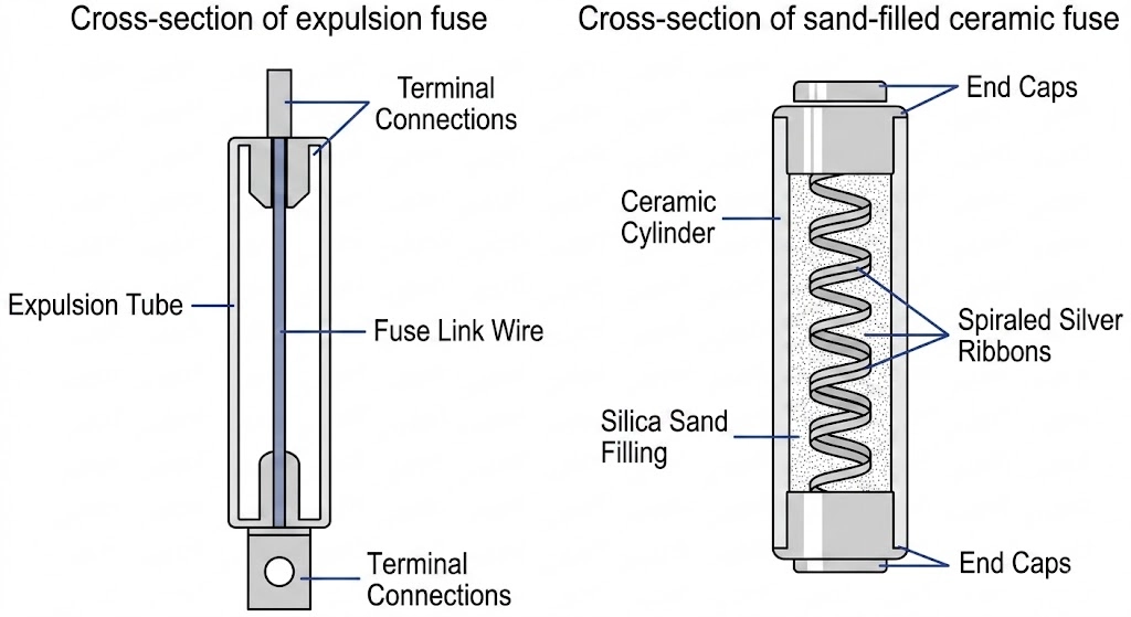
Figure 01:The mechanical expulsion tube of a Bay-O-Net relies on gas generation, whereas current limiting fuses utilize silica sand to form fulgurite.
To grasp how these two technologies coordinate, one must examine their entirely different internal architectures. They do not share the same arc-quenching physics, and applying them correctly requires understanding the limitations of their respective materials.
The Expulsion Principle of Bay-O-Net Fuses
A बेयोनेट फ्यूज असेंबली is an expulsion-style device that relies on the physical elongation and cooling of an electrical arc. Inside the fuse cartridge, a calibrated fusible element is surrounded by an ablative material, typically horn fiber or a highly compressed boric acid compound. When a low-magnitude fault or severe thermal overload occurs, the primary element melts and parts, drawing a high-temperature arc.
The intense heat of this arc instantly vaporizes the inner wall of the ablative tube. This rapid phase change generates a high-pressure burst of de-ionizing gases.
In oil-filled distribution transformers, these gases forcefully expel the arc out of the bottom of the tube and into the surrounding dielectric fluid, extinguishing the arc as the AC waveform naturally crosses the zero-current threshold (0 A).
Because it relies on mechanical expulsion and natural current zero-crossings, this mechanism is inherently slower and heavily dependent on the transformer’s insulating oil to dissipate the resulting heat and gas bubbles safely. It is highly effective for clearing secondary faults up to approximately 3,500 amperes, but the structural housing is mechanically incapable of containing massive, instantaneous energy releases.
The Sand and Silver Arc-Quenching of Current Limiting Fuses
Conversely, a धारा-सीमित फ्यूज does not wait for a natural current zero, nor does it expel any gases into the transformer tank. Its internal structure consists of highly pure silver ribbon elements, precisely stamped with narrow restrictions (notches), spiraled around a non-conductive high-temperature ceramic core. This entire assembly is tightly packed within a dense matrix of high-purity silica sand.
When subjected to a destructive primary fault, the extreme current density causes the silver restrictions to vaporize almost instantaneously—often within 1 to 2 milliseconds. The resulting multiple series arcs interact immediately with the surrounding silica sand.
The extreme thermal energy (≥ 3,000 °C) melts the sand and vaporized silver together, forming a solid, highly resistive glass-like substance called fulgurite. This phase change introduces massive electrical resistance (rapidly exceeding 1,000 Ω) into the circuit.
By violently forcing the internal resistance up, the fuse aggressively chokes the fault current, driving it to zero well before it can reach its destructive prospective peak in the first half-cycle. This self-contained, energy-absorbing physics protects the transformer’s structural integrity from explosive failure modes.
Expert Insight: Material Limitations in Arc Quenching
Bay-O-Net ablative tubes can degrade slightly over years of service if exposed to repeated, minor overcurrent events that approach but do not cross the melting threshold. Unexplained nuisance tripping may indicate an aged, thermally stressed link rather than an active system fault.
The silica sand inside a current limiting fuse must remain perfectly dry and tightly compacted. If a compromised outer casing allows moisture ingress or shifts the sand matrix, the fuse will fail to form fulgurite properly, drastically altering its I²t let-through characteristics.
The Fault Current Spectrum: Defining the Application Boundary
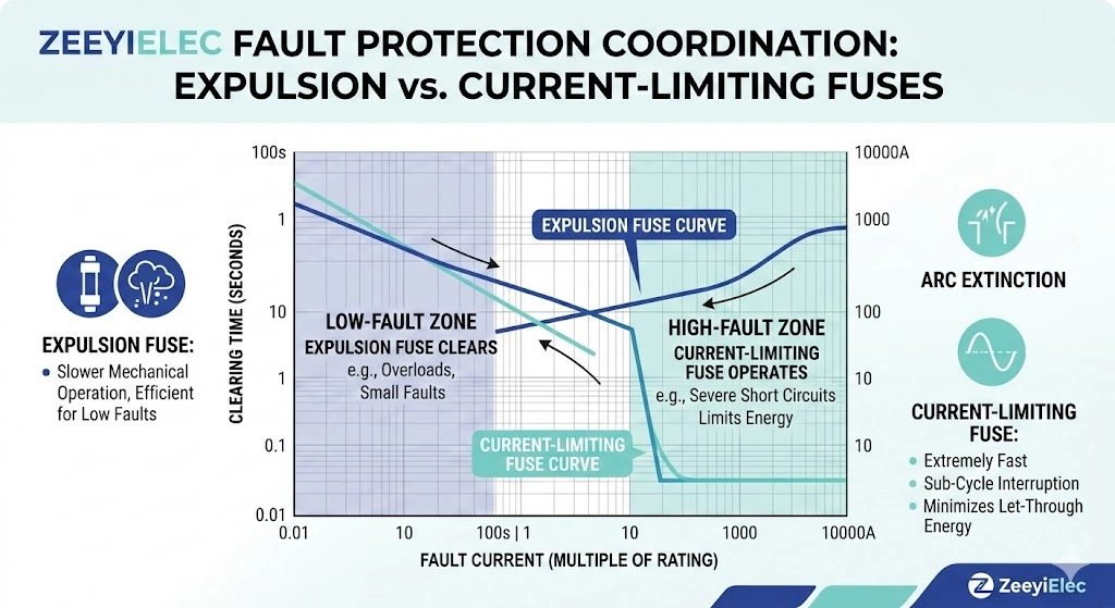
Figure 02:Proper coordination requires a strict margin between the maximum clearing curve of the expulsion fuse and the minimum melting curve of the backup fuse.
The engineering boundary between these two devices is defined by a precise intersection of their Time-Current Characteristic (TCC) curves. Transformer protection demands two fuse technologies working sequentially to create continuous defense across the entire fault current spectrum. Properly mapping this boundary ensures that engineers avoid dangerous specification gaps when utilizing a transformer accessories selection guide.
Low-to-Moderate Faults (Secondary Overloads)
During normal operation, distribution transformer load currents typically measure in the tens or hundreds of amperes. When a secondary fault or progressive thermal overload occurs, the current elevates but is physically restricted by the transformer’s internal impedance.
Bay-O-Net fuses are engineered to clear these low-to-moderate faults up to approximately 3,500 A, ensuring the ΔT (temperature rise) of the insulating oil remains within safe operational limits.
Within this specific spectrum, the expulsion fuse operates as the primary clearing device while the backup current limiting fuse remains entirely passive and undamaged. Field commissioning teams frequently verify that the selected expulsion link will withstand transient anomalies without experiencing nuisance melting prior to energization.
High-Magnitude Bolted Faults (Primary Short Circuits)
If a severe internal winding failure or a primary-side short circuit occurs, the system impedance is bypassed entirely.
During a bolted fault, currents spike to thousands or tens of thousands of amperes within milliseconds, frequently reaching ≥ 50,000 A.
At these extreme levels, an expulsion fuse would explosively fail. Instead, the current limiting fuse assumes control. It is designed to interrupt high-magnitude faults exceeding the expulsion fuse’s threshold within a half-cycle. [VERIFY STANDARD: IEEE Std C37.47] governs the performance and testing criteria for these high-fault interruption components, ensuring they safely contain the arc energy before severe mechanical damage occurs.
Protection Zone Comparison Matrix
पैरामीटर
Bay-O-Net Fuse Zone
Current Limiting Fuse Zone
Fault Type
Secondary overloads, high-impedance faults
Primary bolted faults, major internal shorts
वर्तमान श्रृंखला
Normal load up to ~3,500 A
>3,500 A up to 50,000+ A
Interruption Speed
Multiple cycles (waits for zero-crossing)
< 0.5 cycle (forces current to zero)
मुख्य कार्य
Thermal and secondary fault protection
High-energy arc containment and energy limiting
Coordination Logic: The Sequence of a Fault Event
Understanding how these devices coordinate requires observing them under actual field conditions. In a properly specified two-stage protection system, the sequence of operation is strictly dictated by the fault’s location and its electrical magnitude. This synergistic relationship prevents nuisance outages during acceptable network transients while guaranteeing fail-safe containment during critical equipment failures.
To illustrate this reality, we can examine two distinct operational scenarios that maintenance crews frequently encounter.
Scenario A: Progressive Secondary Overload
When a distribution network experiences a prolonged secondary overload—such as extreme residential demand during a summer heatwave—the load current elevates significantly beyond the transformer’s nameplate rating but remains physically limited by the core and coil impedance.
As progressive thermal degradation occurs, the insulating oil temperature rise (ΔT) accelerates, often pushing top-oil temperatures well past 105 °C.
Because a Bay-O-Net fuse is typically a dual-sensing device, it reacts to both the elevated ambient oil temperature and the continuous overcurrent. The internal expulsion link melts, safely breaking the circuit and protecting the transformer’s cellulose insulation from irreversible thermal aging. From a field diagnostics perspective, when utility crews arrive at the pad-mounted unit, they can pull the Bay-O-Net assembly with a hot stick. Finding a blown expulsion link immediately directs their troubleshooting efforts toward secondary-side issues or load imbalances.
Scenario B: Severe Internal Winding Fault
Conversely, consider an insulation breakdown deep within the primary windings, potentially caused by a lightning transient or long-term moisture ingress into the dielectric paper. This event creates a low-impedance short circuit directly across the high-voltage feed.
If this internal failure allows an instantaneous asymmetrical fault current of 12,000 A to develop, the Bay-O-Net fuse is mechanically incapable of quenching the resulting arc.
Before the expulsion fuse can even begin to react to the current spike, the series-connected current limiting fuse takes over.
By vaporizing its pure silver elements in under a millisecond, it restricts the let-through energy (I²t) to a tiny fraction of the prospective fault magnitude.
The current is choked to zero before the explosive internal pressure can rupture the transformer’s steel tank welds. In this field scenario, the transformer itself is destroyed by the internal short circuit, but the current limiting fuse successfully prevents an oil fire, mitigating safety risks to adjacent equipment and personnel.
Expert Insight: Field Verification of Handoff Curves
When mapping Time-Current Curves (TCC) on logarithmic paper, engineers must maintain a strict safety margin between the two devices. A minimum 10% current margin and 10% time margin should exist between the Bay-O-Net’s maximum clearing curve and the Current Limiting fuse’s minimum melting curve.
Failure to maintain this clearance risks “fatiguing” the current limiting fuse. If a severe secondary fault causes partial melting of the silver element before the Bay-O-Net clears, the current limiting fuse becomes permanently weakened, severely compromising its ability to handle a future primary fault.
Field Maintenance and Replacement Realities
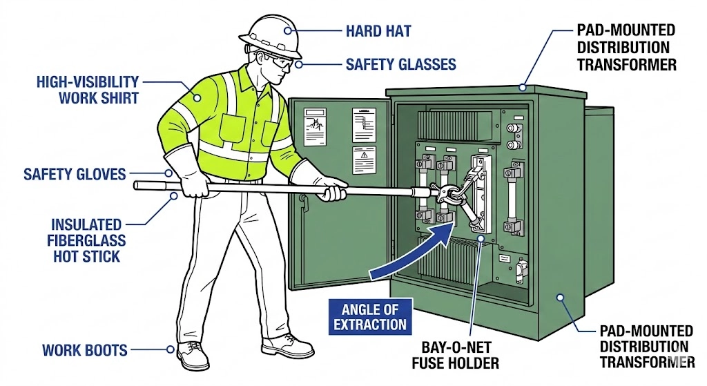
Figure 03:Bay-O-Net assemblies allow for external dead-front extraction using an insulated hot stick after venting internal tank pressure.
The physical construction of these two fuse types dictates completely different field maintenance protocols. When a utility crew responds to an outage, their operational workflow depends heavily on which stage of the protection system has operated.
Safely Servicing Externally Removable Fuses
A Bay-O-Net fuse assembly is designed as a highly accessible protection interface. It combines a transformer-mounted housing and a replaceable fuse holder structure to support safe maintenance access. These 15/25kV class assemblies are engineered with dead-front safety and allow for hot-stick operation without opening the main transformer tank.
From a field experience perspective, replacing an expulsion link requires strict procedural adherence.
Before unlatching the Bay-O-Net holder, field personnel must pull the pressure relief valve to vent any accumulated internal tank pressure, which can frequently reach ≥ 5 psi depending on the ambient oil temperature.
Using an insulated fiberglass hot stick, the operator unlatches the handle and withdraws the fuse holder. A critical field reality is allowing the assembly to drain for several seconds before fully extracting it; pulling the assembly out of the oil bath too rapidly can draw a contaminated oil trail, posing a flashover risk. If the expulsion link is blown, crews typically investigate for downstream secondary faults before installing a replacement link and re-energizing.
Diagnostics After a Current Limiting Fuse Operation
Conversely, if diagnostics reveal that the backup current limiting fuse has operated, the maintenance reality shifts from a routine replacement to a critical failure investigation. A systematic field failure diagnosis workflow isolates root causes before destructive repeat failures occur.
Because current limiting fuses are typically mounted internally beneath the oil level or within the tank, they are not designed for routine external replacement. An operated current limiting fuse clearly indicates that a massive fault bypassed the secondary protection—typically a severe internal winding short or a major dielectric breakdown.
In these scenarios, simply replacing the fuse and re-energizing is highly dangerous; the transformer’s internal insulation resistance has likely dropped to ≤ 1 MΩ, and a second energization could result in a tank rupture.
The unit must be tagged, taken completely out of service, shipped to a repair facility, and subjected to comprehensive core and coil testing (such as sweep frequency response analysis or dissolved gas analysis) to verify the integrity of the equipment.
Specifying Coordinated Fuses for Distribution Projects
Specifying a coordinated two-stage protection system requires precise matching of electrical parameters to prevent dangerous specification gaps. Procurement teams must ensure that the continuous current ratings, voltage classes, and interruption capabilities of both devices align perfectly with the transformer’s nameplate data.
For example, when sourcing a primary protection package for a 15/25kV class distribution transformer, the first step is selecting the correct बेयोनेट फ्यूज असेंबली. The assembly must feature an appropriate Basic Insulation Level (BIL), typically 150 kV, to withstand system transient voltage spikes. The internal expulsion link must be sized to carry the normal full-load current while safely clearing low-to-moderate faults without nuisance tripping.
Once the expulsion fuse’s TCC curve is locked in, engineers select the backup धारा-सीमित फ्यूज.
The current limiting fuse must have a minimum interrupting rating that strictly exceeds the maximum available system fault current—frequently specified at ≥ 50,000 A for stiff utility grids.
Its minimum melting curve must intersect the Bay-O-Net’s maximum clearing curve precisely at the critical crossover point to ensure a precise handoff during a massive fault event. ZeeyiElec provides comprehensive technical support to assist engineers and procurement teams in mapping these complex coordination boundaries. Share your project’s voltage class, available fault current, and transformer kVA rating with our engineering team for specialized model matching and rapid RFQ support.
अक्सर पूछे जाने वाले प्रश्न
What is the maximum fault current a Bay-O-Net fuse can interrupt?
A Bay-O-Net fuse typically clears low-to-moderate faults up to approximately 1,000 to 3,500 amperes, depending heavily on the specific voltage class and the temperature of the surrounding insulating oil. For fault currents exceeding this threshold, it must be paired with a backup current limiting fuse to prevent the mechanical expulsion housing from failing explosively under pressure.
Do I always need both fuse types for a distribution transformer?
While smaller transformers on rural systems with very low available fault currents might theoretically operate with only an expulsion fuse, most modern medium-voltage distribution transformers rated above 50 kVA require both technologies. This dual-fuse logic ensures absolute safety and protection across the entire spectrum, from minor 200-ampere secondary overloads to 50,000-ampere primary bolted faults.
Can a current limiting fuse be replaced externally with a hot stick?
Unlike Bay-O-Net assemblies which are specifically engineered for external dead-front hot-stick operation, most current limiting fuses are hard-mounted internally under the oil level or bolted to the core inside the transformer tank. Replacing them usually requires de-energizing the transformer, opening the tank lid, and pulling the internal assembly, because a blown current limiting fuse almost always indicates a severe internal winding failure requiring deeper electrical testing.
Why do current limiting fuses prevent mechanical equipment damage?
Current limiting fuses are precisely engineered to melt their internal silver ribbons and force the fault current to zero within the very first half-cycle of the AC electrical waveform. By interrupting the fault before it can reach its fully destructive peak magnitude, they drastically reduce the intense magnetic and thermal stresses that would otherwise warp internal copper windings or rupture the external steel transformer tank.
What causes a Bay-O-Net fuse to blow under normal load conditions?
Nuisance operations under seemingly normal electrical loads are frequently caused by excessive oil temperature rise rather than simple overcurrent, because modern expulsion links are dual-sensing (reacting to both ambient fluid temperature and internal current). Prolonged high summer ambient temperatures, inadequate transformer cooling airflow, or incorrect initial fuse sizing can easily push the fuse link past its 105 to 145 degree Celsius melting point even if the load current remains perfectly within rated limits.
योयो शी
योयो शी ZeeyiElec के लिए लिखती हैं, जहाँ उनका ध्यान मध्यम-वोल्टेज सहायक उपकरणों, ट्रांसफॉर्मर घटकों और केबल सहायक समाधानों पर केंद्रित है। उनके लेख उत्पाद अनुप्रयोगों, तकनीकी मूल बातों और वैश्विक विद्युत उद्योग के खरीदारों के लिए आपूर्ति संबंधी अंतर्दृष्टि को कवर करते हैं।.