ऑफ़-सर्किट टैप चेंजर क्या है? ऑफ-सर्किट टैप चेंजर (जिसे डी-एनर्जाइज़्ड टैप चेंजर या ऑफ-लोड टैप चेंजर भी कहा जाता है) एक यांत्रिक स्विचिंग उपकरण है, जिसका उपयोग केवल तब किया जाता है जब ट्रांसफॉर्मर विद्युत्-विहीन हो। इसकी मुख्य विशेषता इसकी परिचालन सीमा है: इसे विशेष रूप से विद्युत्-विहीन वोल्टेज समायोजन के लिए डिज़ाइन किया गया है और इसे कभी भी लोड के तहत संचालित नहीं किया जाना चाहिए।.
मूलभूत कार्य
के व्यापक पारिस्थितिकी तंत्र में, स्थिर वोल्टेज विनियमन के लिए मूलभूत तंत्र के रूप में कार्य करता है। वितरण नेटवर्क लंबी ओवरहेड लाइनों या भूमिगत केबल मार्गों में अंतर्निहित वोल्टेज गिरावटों के कारण शायद ही कभी पूरी तरह से स्थिर वोल्टेज प्रदान करते हैं। इन स्थिर-अवस्था परिवर्तनों की भरपाई करने और उपभोक्ताओं को सही द्वितीयक वोल्टेज प्रदान सुनिश्चित करने के लिए, टैप चेन्जर ट्रांसफॉर्मर की वाइंडिंग में सक्रिय टर्नों की संख्या बदलता है।.
वाइंडिंग से जुड़े विभिन्न स्थिर संपर्कों (टैप्स) के बीच एक चालक सेतु को भौतिक रूप से स्थानांतरित करके, यह तंत्र ट्रांसफार्मर के वोल्टेज अनुपात को संशोधित करता है। ये यांत्रिक स्विच वितरण प्रणालियों में विशिष्ट विद्युत मापदंडों को समायोजित करने के लिए डिज़ाइन किए गए हैं। सामान्य यूटिलिटी विन्यास 15 kV, 25 kV, और 35 kV की सिस्टम वोल्टेज श्रेणियों के लिए रेट किए जाते हैं, जो 63A या 125A की निरंतर धारा रेटिंग संभालते हैं। आंतरिक संपर्कों को स्थिर विद्युत निरंतरता बनाए रखनी चाहिए और डाइइलेक्ट्रिक तरल में डूबी दशकों की निरंतर सेवा के दौरान स्थानीय गर्मी को रोकने के लिए अत्यंत कम संपर्क प्रतिरोध होना चाहिए।.
कार्यात्मक सीमाएँ
इस उपकरण की सबसे महत्वपूर्ण संरचनात्मक और परिचालन संबंधी विशिष्टता इसके नाम में निहित है। यह एकमात्र अंतर—ऊर्जायुक्त बनाम ऊर्जाहीन संचालन—इन दोनों उपकरणों के अनुप्रयोग की सीमा निर्धारित करता है। दोनों घटक वितरण ट्रांसफॉर्मरों पर पाए जाते हैं, लेकिन एक के विपरीत, जिसमें सुरक्षित रूप से धारा को बाधित करने के लिए विशिष्ट आर्क-निष्कासन तंत्र होते हैं, एक ऑफ-सर्किट टैप चेन्जर में सक्रिय विद्युत भार को तोड़ने की भौतिक क्षमता पूरी तरह से अनुपस्थित होती है।.
चूंकि इसमें ये आर्क-निवारण सुविधाएँ नहीं हैं, ट्रांसफॉर्मर के ऊर्जा-युक्त होने पर इस उपकरण का संचालन करने पर एक विशाल, अनियंत्रित विद्युत आर्क उत्पन्न होगा। लोड के तहत ऑफ-सर्किट टैप चेंजर का संचालन संपर्कों को क्षति पहुँचाता है और ट्रांसफॉर्मर के आंतरिक दोषों का जोखिम बढ़ाता है। इसलिए सुरक्षित संचालन के लिए फील्ड कर्मियों को वोल्टेज अनुपात में कोई भी यांत्रिक समायोजन करने से पहले यह भौतिक रूप से सत्यापित करना आवश्यक है कि ट्रांसफॉर्मर पूरी तरह से ऊर्जा-मुक्त और ग्राउंडेड है।.
कार्य सिद्धांत: टर्न रेशियो का संशोधन
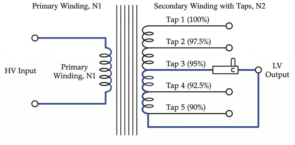
चित्र-01: विद्युत आरेख जो दर्शाता है कि यांत्रिक संपर्क पुल उच्च-वोल्टेज वाइंडिंग में सक्रिय कुंडल संख्या को कैसे बदलता है।.
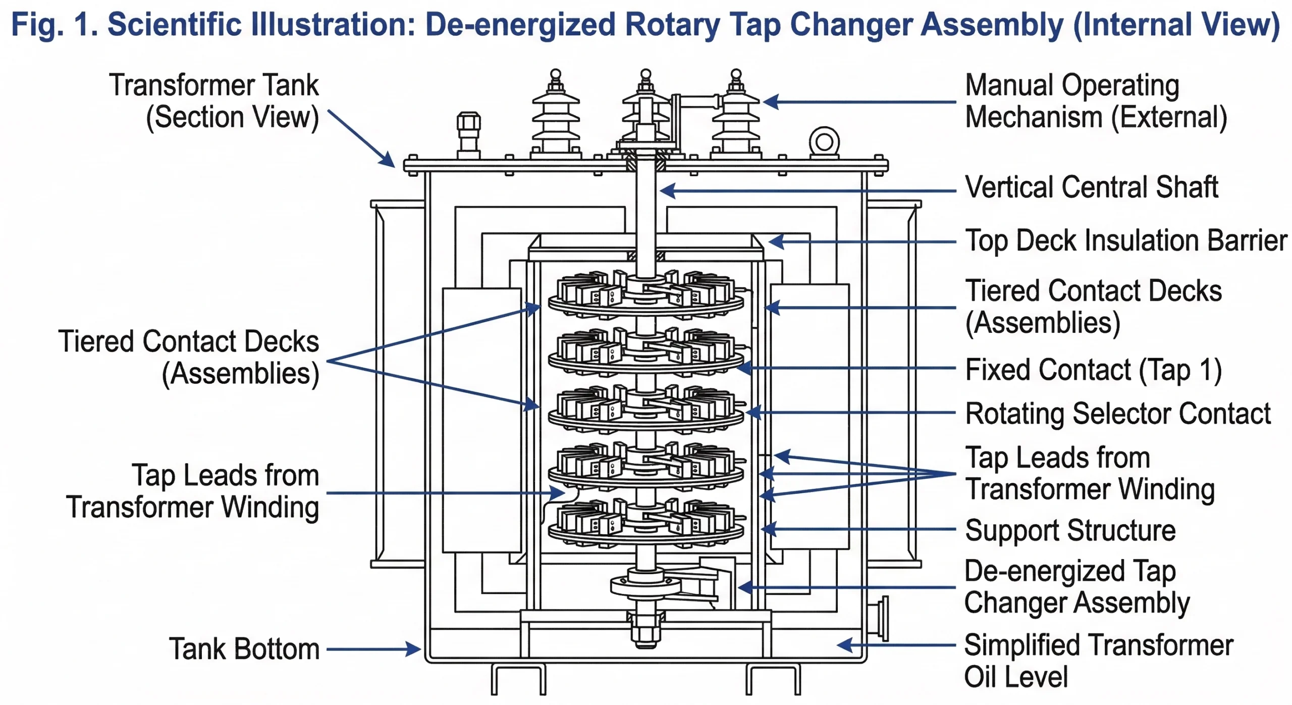
ऑफ-सर्किट टैप चेंजर का मूल सिद्धांत ट्रांसफॉर्मर की वाइंडिंग में सक्रिय कुंडलियों की भौतिक संख्या को बदलना है। कुंडल अनुपात को बदलकर यह उपकरण ग्रिड की आवश्यकताओं के अनुरूप द्वितीयक आउटपुट वोल्टेज को प्रभावी रूप से बढ़ा या घटाता है, और यह समायोजन केवल तब करता है जब ट्रांसफॉर्मर ऑफलाइन हो।.
ट्रांसफॉर्मर टैप्स की भूमिका
ट्रांसफॉर्मर विद्युत चुम्बकीय प्रेरण के सिद्धांत पर काम करते हैं, जहाँ प्राथमिक वोल्टेज और द्वितीयक वोल्टेज का अनुपात उनके तारों की कुंडलियों की संख्या के अनुपात के समानुपाती होता है। वोल्टेज को समायोजित करने के लिए, निर्माता वाइंडिंग के विभिन्न हिस्सों से “टैप्स”—भौतिक संपर्क बिंदु—बाहर निकालते हैं। अधिकांश वितरण ट्रांसफॉर्मरों में, ये टैप्स उच्च-वोल्टेज (HV) वाइंडिंग पर स्थित होते हैं। एचवी पक्ष पर टैप तंत्र को रखना एक मौलिक इंजीनियरिंग विकल्प है क्योंकि एचवी वाइंडिंग में काफी कम धारा प्रवाहित होती है। उदाहरण के लिए, 15 kV की प्राथमिक वाइंडिंग में 50A की धारा हो सकती है, जबकि 400V की द्वितीयक वाइंडिंग में 1800A से अधिक धारा प्रवाहित होती है। इन कम धाराओं का प्रबंधन करने से धात्विक संपर्कों का आवश्यक भौतिक आकार काफी कम हो जाता है और यांत्रिक घटकों पर दीर्घकालिक तापीय तनाव को कम किया जाता है।.
संपर्कों का यांत्रिक सेतुकरण
टैप चेंजर की यांत्रिक क्रिया इन वाइंडिंग कनेक्शनों का एक संरचित, चरण-दर-चरण भौतिक ब्रिजिंग है। जब बाहरी हैंडल घुमाया जाता है, तो एक इन्सुलेटेड केंद्रीय शाफ्ट चलती संपर्कों के एक सेट को चलाता है—अक्सर स्प्रिंग-लोडेड तांबे या पीतल के ब्रिज। ये चलती संपर्कों टैप लीड्स से जुड़े स्थिर संपर्कों के पार स्लाइड या रोल करके अपनी जगह पर आ जाते हैं। एक मानक वितरण टैप चेंजर 5 विशिष्ट परिचालन स्थितियाँ प्रदान करता है। ये स्थितियाँ वाइंडिंग के विभिन्न खंडों से संबंधित होती हैं। संपर्क पुल को स्थानांतरित करने पर तांबे या एल्यूमीनियम कॉइल की विशिष्ट कुंडलियों को सक्रिय विद्युत परिपथ में प्रभावी रूप से शामिल या बाहर रखा जाता है।.
वोल्टेज आउटपुट गणना की मूल बातें
चूंकि द्वितीयक वोल्टेज प्राथमिक कुंडल के सटीक संख्या में संलग्न मोड़ों पर निर्भर करता है, इसलिए चयनित टैप स्थिति के आधार पर आउटपुट सीधे गणना किया जा सकता है। अधिकांश ऑफ-सर्किट टैप चेंजर्स समान वृद्धि में वोल्टेज समायोजन प्रदान करते हैं, आमतौर पर प्रति चरण 2.5%।.
यह संबंध मुख्य ट्रांसफॉर्मर समीकरण द्वारा परिभाषित किया गया है: VS = वीP × (एनS / एनP), जहाँ V वोल्टेज को दर्शाता है, N सक्रिय कुंडलियों की संख्या को दर्शाता है, और उपसर्ग S तथा P द्वितीयक और प्राथमिक को दर्शाते हैं।.
एक मानक 5-स्थिति टैप चेंजर के लिए, विद्युत विन्यास आमतौर पर निम्नलिखित परिणाम देते हैं:
स्थिति 1: +5.0% (अधिकतम प्राथमिक कुंडल संलग्न, न्यूनतम द्वितीयक वोल्टेज आउटपुट)
स्थिति 2: +2.5%
स्थिति 3: नाममात्र (0% समायोजन)
स्थिति 4: -2.5%
स्थिति 5: -5.0% (न्यूनतम प्राथमिक कुंडल संलग्न, उच्चतम द्वितीयक वोल्टेज आउटपुट)
यह मानकीकृत स्टेप विन्यास, जो अक्सर मानक यूटिलिटी आवश्यकताओं—[प्राधिकरण लिंक स्रोत आवश्यक: IEEE Std C57.12.00 तरल-डूबे वितरण ट्रांसफॉर्मरों के लिए सामान्य आवश्यकताएँ]—द्वारा नियंत्रित होता है, यह सुनिश्चित करता है कि नेटवर्क ऑपरेटर लंबे वितरण फीडरों में होने वाले पूर्वानुमेय वोल्टेज ड्रॉप को विश्वसनीय रूप से सुधार सकें।.
[विशेषज्ञ की अंतर्दृष्टि: फील्ड टैप चयन]
आयोगन आधाररेखा: साइट इंस्टॉलेशन के दौरान हमेशा प्री-एनर्जीकरण टैप स्थिति को रिकॉर्ड करें और सुनिश्चित करें कि यह गणना किए गए स्थानीय ग्रिड वोल्टेज प्रोफ़ाइल से मेल खाती है।.
मौसमी समायोजन नहीं: ये उपकरण दैनिक या मौसमी वोल्टेज विनियमन के लिए डिज़ाइन नहीं किए गए हैं; अत्यधिक यांत्रिक चक्रण आंतरिक संपर्कों की अखंडता को कमजोर कर देता है।.
अनुपात सत्यापन: टैंक सील करने और ऊर्जा प्रदान करने से पहले यह सुनिश्चित करने के लिए कि यांत्रिक ब्रिज ठीक से स्थापित हो गया है, सभी फेजों पर ट्रांसफॉर्मर टर्नस् रेशियो (TTR) टेस्टर का उपयोग करें।.
आंतरिक यांत्रिकी: रैखिक बनाम घूर्णी विन्यास
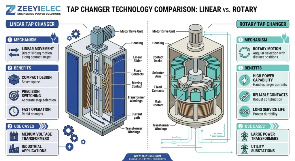
चित्र-02: एक रैखिक टैप चेंजर की स्लाइडिंग संपर्क क्रिया और एक घूर्णी प्रकार की झाड़ू जैसी वृत्ताकार गति के बीच संरचनात्मक तुलना।.
ऑफ-सर्किट टैप चेंजर्स विन्यास योग्य संरचनाओं में निर्मित होते हैं, जिनमें सबसे प्रमुख रैखिक और घूर्णी प्रकार हैं। इन यांत्रिक विन्यासों के बीच चयन काफी हद तक ट्रांसफार्मर टैंक की आंतरिक स्थानिक बाधाओं, वाइंडिंग लीड रूटिंग, और स्विच किए जा रहे फेजों की संख्या पर निर्भर करता है। दोनों संरचनात्मक प्रकार एक ही मौलिक विद्युत परिणाम प्राप्त करने के लिए डिज़ाइन किए गए हैं, लेकिन वे पूरी तरह से अलग गति पथों के माध्यम से संपर्कों का भौतिक सेतुकरण करते हैं। इसके अलावा, दोनों को कड़े यांत्रिक स्थायित्व और तापीय आवश्यकताओं का पालन करना चाहिए [मानक सत्यापित करें: ऑफ-सर्किट टैप चेंजर संपर्क प्रतिरोध और यांत्रिक संचालन चक्रों के लिए IEC 60214-1 आवश्यकताएँ]।.
रेखीय टैप चेंजर्स
रेखीय, या स्लाइडिंग, टैप चेंजर्स सीधी रेखा में यांत्रिक गति के माध्यम से काम करते हैं। एक इन्सुलेटिंग रॉड या थ्रेडेड रैक-एंड-पिनियन तंत्र एक चालक पुल को स्थिर टैप स्टड्स की एक पंक्ति में रेखीय रूप से स्थानांतरित करता है।.
यह डिज़ाइन कॉइल सिलेंडर के ठीक बगल में ऊर्ध्वाधर रूप से माउंट करने के लिए अत्यधिक स्थान-कुशल है। यह आमतौर पर मानक मध्यम-वोल्टेज वितरण अनुप्रयोगों में 63A या 125A की निरंतर धारा रेटिंग संभालता है। क्षेत्रीय स्थापना के दृष्टिकोण से, एकल-चरण पोल-माउंटेड ट्रांसफॉर्मरों के लिए रैखिक डिज़ाइनों को अत्यधिक पसंद किया जाता है। सरल ऊर्ध्वाधर क्रियाकलाप शीर्ष आवरण पर लगे ऑपरेटिंग हैंडल के साथ पूरी तरह मेल खाता है, जो आंतरिक यांत्रिक जुड़ाव को सरल करता है और रखरखाव समायोजनों के दौरान ऑपरेटिंग रॉड के अटकने या जाम होने के जोखिम को कम करता है।.
रोटरी टैप चेंजर्स
रोटरी, या वृत्ताकार, टैप चेंजर्स स्थिर टैप संपर्कों को केंद्रीय इन्सुलेटेड ड्राइविंग शाफ्ट के चारों ओर एक निश्चित वृत्ताकार त्रिज्या में व्यवस्थित करते हैं। बाहरी हैंडल को घुमाने पर यह शाफ्ट घूमता है, जिससे स्प्रिंग-लोडेड चलती संपर्कों को एक स्थिर स्टड से अगले तक ले जाता है।.
यह विन्यास त्रि-चरण वितरण ट्रांसफॉर्मरों के लिए मानक विकल्प है। एकल, विस्तारित केंद्रीय शाफ्ट आसानी से तीन अलग-अलग, एक के ऊपर एक रखे संपर्क डेकों को एक साथ चला सकता है—प्रत्येक चरण के लिए एक। चलती संपर्कों का स्थिर स्टड्स के खिलाफ घूर्णी पोंछने वाला क्रिया एक महत्वपूर्ण तकनीकी लाभ प्रदान करता है: यह एक स्व-सफाई तंत्र के रूप में कार्य करता है जो डाइइलेक्ट्रिक तेल में स्थानीय कार्बन जमाव या ऑक्सीकरण को खुरचकर हटा देता है।.
अत्यंत निम्न संपर्क प्रतिरोध बनाए रखना, सामान्यतः प्रति चरण ≤ 500 μΩ, अत्यंत महत्वपूर्ण है। यदि संपर्क प्रतिरोध बढ़ता है, तो परिणामी I2आर के नुकसान से स्थानीय स्तर पर ताप उत्पन्न होगा और संभावित रूप से आसपास के इन्सुलेटिंग तेल की गुणवत्ता खराब हो सकती है।.
कारखाने में असेंबली और फील्ड निरीक्षण के दौरान, रोटरी स्विचों के लिए मल्टी-डेक शाफ्ट का सटीक ऊर्ध्वाधर संरेखण आवश्यक होता है। यदि स्टैक्ड फेज डेक्स को असमान रूप से टॉर्क किया जाए या वे विकृत हो जाएँ, तो परिणामी यांत्रिक विक्षेपण निचले डेक पर अपूर्ण बैठने का कारण बन सकता है, भले ही ऊपरी डेक लॉक और सुरक्षित स्थिति दिखा रहा हो। यह असंगत संरेखण उच्च-प्रतिरोध वाले आंशिक संपर्क का निर्माण करता है, जो ऊर्जा प्रदान करते ही शीघ्रता से तापीय विफलता का कारण बनता है।.
पूर्ण नियम: केवल ऊर्जा रहित संचालन
आलोचनात्मक चेतावनी: एक ऑफ-सर्किट टैप चेंजर पूरी तरह से एक डी-एनर्जाइज़्ड स्विचिंग उपकरण है। ट्रांसफार्मर के लोड के तहत ऊर्जा-युक्त होने पर, या केवल द्वितीयक लोड के बिना चुम्बकीकृत होने पर टैप चेंजर हैंडल का संचालन करने से उपकरण की विनाशकारी विफलता, तेल का गंभीर दूषण और क्षेत्रीय कर्मियों के लिए गंभीर सुरक्षा खतरा उत्पन्न होगा।.
आर्क अवरोधन का भौतिकी (यह क्यों विफल होता है)
लोड स्विचिंग क्यों सख्त रूप से निषिद्ध है, यह समझने के लिए फील्ड इंजीनियरों को विद्युत संपर्क अलगाव के भौतिकी को देखना चाहिए। जब कोई स्विचिंग उपकरण सक्रिय धारा को बाधित करता है, तो अलग हो रहे संपर्कों के बीच का डाइइलेक्ट्रिक माध्यम टूट जाता है, जिससे उच्च तापमान वाला प्लाज्मा आर्क बनता है।.
लोडब्रेक स्विच विशेष रूप से इस घटना को संभालने के लिए डिज़ाइन किया गया है। इसमें स्प्रिंग-लोडेड क्विक-मेक/क्विक-ब्रेक तंत्र, आर्क-निष्क्रिय करने वाली सामग्रियाँ या वैक्यूम इंटरप्टर शामिल होते हैं, जो मिलीसेकंड के भीतर आर्क को फैलाने, ठंडा करने और बुझाने का काम करते हैं। इसके विपरीत, ऑफ-सर्किट टैप चेंजर में ये आर्क-निवारक सुविधाएँ बिलकुल नहीं होतीं। चलती संपर्क बिंदु धीरे-धीरे चलते हैं, जो ऑपरेटर के हाथ के मैनुअल घुमाव का सीधे अनुसरण करते हैं।.
क्योंकि निकटवर्ती टैप स्टड्स के बीच का भौतिक अंतर आश्चर्यजनक रूप से छोटा होता है—अक्सर मानक वोल्टेज वर्ग के आधार पर केवल 5 मिमी से 12 मिमी तक—धीमी गति से चलने वाला संपर्क पुल एक निरंतर, स्थायी आर्क खींचता है। डाइइलेक्ट्रिक खनिज तेल में, इस अनबुझी विद्युत आर्क का कोर तापमान तेजी से 5,000 °C से अधिक हो सकता है।.
गलत संचालन के वास्तविक परिणाम
मैदानी परिस्थितियों में, इस पूर्ण नियम की अवहेलना के परिणाम तत्काल और विनाशकारी होते हैं। जब निरंतर आर्क आसपास के ट्रांसफॉर्मर तेल को वाष्पित कर देता है, तो यह मुख्यतः हाइड्रोजन और एसिटिलीन सहित बड़ी मात्रा में ज्वलनशील गैसें उत्पन्न करता है। इस तीव्र गैस उत्पादन से सीलबंद ट्रांसफॉर्मर टैंक के अंदर गंभीर दबाव वृद्धि होती है। यदि अचानक दबाव ट्रांसफॉर्मर के दबाव राहत उपकरण की वेंटिंग क्षमता से अधिक हो जाए, तो टैंक फट सकता है या विकृत हो सकता है।.
भले ही आपदाजनक टैंक विफलता होने से पहले आर्क स्वयं बुझ जाए, आंतरिक क्षति अपरिवर्तनीय रहती है। अत्यधिक गर्मी पीतल या तांबे के संपर्कों को पिघला देती है, जिससे कम प्रतिरोध वाले ब्रिजिंग के लिए आवश्यक सटीक मशीनीकृत सतहें नष्ट हो जाती हैं। इसके अलावा, आर्क इन्सुलेटिंग तेल को गंभीर रूप से कार्बोनाइज़ कर देता है।.
यह कार्बन कण पदार्थ पूरे टैंक में फैल जाता है, तेल के डाइइलेक्ट्रिक ब्रेकडाउन वोल्टेज को नाटकीय रूप से कम कर देता है (अक्सर इसे 30 kV की न्यूनतम परिचालन सीमा से काफी नीचे धकेल देता है) और सेलुलोज़ कागज़ इन्सुलेशन पर एक परत चढ़ा देता है। एक बार जब तेल भारी मात्रा में कार्बनयुक्त हो जाता है और संपर्कों में गड्ढे हो जाते हैं, तो आंतरिक प्रतिरोध बढ़ जाता है, ΔT (तापमान वृद्धि) तेज हो जाती है, और पूरे ट्रांसफार्मर को आमतौर पर महंगी मरम्मत के लिए सेवा से हटाना पड़ता है।.
[विशेषज्ञ की अंतर्दृष्टि: सुरक्षा और सत्यापन प्रोटोकॉल]
LOTO प्रवर्तन: बाहरी हैंडल पर भौतिक पैडलॉक व्यवस्था को ऊर्जा युक्त स्विचिंग को पूर्णतः रोकने के लिए सख्त लॉकआउट/टैगआउट प्रक्रियाओं में एकीकृत किया जाना चाहिए।.
द्वितीयक जाँचें: केवल हैंडल की पैडलॉक स्थिति पर भरोसा न करें; ऑपरेटरों को किसी भी यांत्रिक हेरफेर से पहले ट्रांसफॉर्मर बुशिंग्स पर वोल्टेज की अनुपस्थिति की हमेशा जांच करनी चाहिए।.
निदानात्मक तेल नमूनाकरण: यदि क्षेत्र में आकस्मिक अंडर-लोड स्विचिंग का संदेह हो, तो सक्रिय आर्किंग का संकेत देने वाले बढ़े हुए एसिटिलीन और हाइड्रोजन स्तरों की जांच के लिए तुरंत घुलित गैस विश्लेषण (DGA) का नमूना लें।.
मैदानी स्थापना और संचालन इंटरफ़ेस
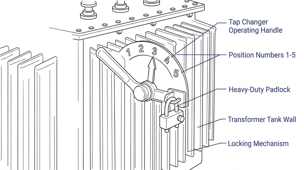
FIG-03: बाहरी संचालन इंटरफ़ेस में क्रमांकित संकेतक प्लेट, लोकेशन पिन और भौतिक पैडलॉक प्रावधान शामिल हैं, जो विद्युत्-विहीन संचालन को लागू करते हैं।.
जबकि ऑफ-सर्किट टैप चेन्जर का संपर्क तंत्र ट्रांसफॉर्मर के इन्सुलेटिंग तेल में डूबा रहता है, ऑपरेटिंग इंटरफ़ेस को टैंक के बाहरी हिस्से पर फील्ड कर्मियों के लिए सुलभ रहना चाहिए। आंतरिक द्रव और बाहरी वातावरण के बीच इस सीमा की अखंडता ट्रांसफॉर्मर के समग्र परिचालन जीवनकाल में एक महत्वपूर्ण कारक है।.
टैंक माउंटिंग और सीलिंग
टैप चेंजर शाफ्ट एक सटीक रूप से मशीनीकृत माउंटिंग बॉस के माध्यम से ट्रांसफार्मर टैंक की दीवार या शीर्ष आवरण को पार करता है। इस प्रवेश को सुरक्षित करने के लिए मजबूत सीलिंग तकनीकों की आवश्यकता होती है, जिनमें आमतौर पर उच्च-तापमान NBR (नाइट्राइल ब्यूटाडाइन रबर) या वाइटॉन O-रिंग्स का उपयोग किया जाता है।.
कठोर क्षेत्रीय परिस्थितियों में, इन सीलों को अत्यधिक तापमान उतार-चढ़ाव सहना पड़ता है, जो अक्सर शीतकालीन वातावरण में -40 °C से लेकर चरम ग्रीष्मकालीन भार के दौरान +105 °C से अधिक तेल संचालन तापमान तक होता है। यदि सीलिंग ग्लैंड यूवी विकिरण या गलत इंस्टॉलेशन टॉर्क (आमतौर पर फ्लैंज डिज़ाइन के आधार पर 15 से 25 N·m) के कारण क्षतिग्रस्त हो जाती है, तो नमी का प्रवेश अनिवार्य हो जाता है।.
किसी दोषपूर्ण टैप चेंजर सील से प्रवेश करने वाले जल की अतिसूक्ष्म मात्रा भी इन्सुलेटिंग तेल की विद्युत-आइसोलेशन क्षमता को तीव्रता से कम कर देती है, जिससे फेज-टू-ग्राउंड फॉल्ट का जोखिम गंभीर रूप से बढ़ जाता है। पूर्ण पर्यावरणीय सीलिंग पर यह जोर उतना ही महत्वपूर्ण है जितना कि टैंक के बाहरी हिस्से में स्थापना करते समय या डाउनस्ट्रीम नेटवर्क कनेक्शनों के लिए विनिर्देश तय करते समय होता है।.
संचालन और स्थिति सत्यापन संभालें
बाहरी संचालन हैंडल आमतौर पर एक प्रमुख स्थिति संकेतक प्लेट से सुसज्जित होता है, जिस पर 1 से 5 तक संख्याएँ अंकित होती हैं, और एक यांत्रिक लोकेटिंग पिन होता है। क्षेत्र समायोजनों के दौरान, तकनीशियन को लॉकिंग पिन को अलग करने के लिए स्प्रिंग-लोडेड हैंडल को बाहर की ओर खींचना होता है, उसे नई वांछित स्थिति में घुमाना होता है, और पिन को संबंधित डेंट होल में पूरी तरह से बैठने देना होता है।.
एक महत्वपूर्ण फील्ड इंस्टॉलेशन अंतर्दृष्टि इस सीटिंग प्रक्रिया का भौतिक सत्यापन है। अनुभवी लाइनसमैन केवल दृश्य संरेखण पर भरोसा नहीं करते; वे यह सुनिश्चित करते हैं कि हैंडल भौतिक रूप से मजबूती से अपनी जगह पर “क्लिक” करे। यदि लोकेटिंग पिन डेटेंट के बाहर टिकी रहे, तो आंतरिक संपर्क दो टैप स्थितियों के बीच यात्रा के मध्य में लटक सकते हैं। पुनः ऊर्जा प्रदान करने पर, यह तैरता हुआ संपर्क परिदृश्य एक उच्च-प्रतिरोध बोतल-गला या एक आंशिक खुला सर्किट बनाता है, जो तुरंत तीव्र स्थानीय गर्मी उत्पन्न करेगा और शीघ्र विफलता का कारण बनेगा। प्रशिक्षित नहीं किए गए कर्मियों द्वारा अनधिकृत या आकस्मिक संचालन को रोकने के लिए, हैंडल असेंबली में लगभग सार्वभौमिक रूप से एक भौतिक पैडलॉक की व्यवस्था शामिल होती है, जो डिवाइस को सख्ती से इसकी कमीशन की गई स्थिति में सुरक्षित रखती है।.
खरीद के लिए तकनीकी विनिर्देश
वितरण ट्रांसफॉर्मर के निर्माण के लिए ऑफ-सर्किट टैप चेन्जर निर्दिष्ट करते समय, खरीद टीमें अवयव की क्षमताओं को परिचालन वातावरण के साथ सटीक रूप से संरेखित करें। अधूरे विनिर्देश असेंबली के दौरान सहायक उपकरणों के मेल न खाने और उत्पादन में देरी का एक महत्वपूर्ण हिस्सा होते हैं।.
आवश्यक विद्युत पैरामीटर
टैप चेंजर को ट्रांसफॉर्मर की अधिकतम डिज़ाइन रेटिंग्स के बराबर या उससे अधिक होना चाहिए।.
मानक उपयोगिता और औद्योगिक अनुप्रयोगों के लिए सटीक वोल्टेज वर्गों की आवश्यकता होती है, जो आमतौर पर 15 kV, 25 kV या 35 kV विन्यासों में उपलब्ध होते हैं। इसके अलावा, निरंतर धारा रेटिंग को सख्ती से परिभाषित किया जाना चाहिए; मानक वितरण क्षमताएँ आमतौर पर 63A या 125A पर निर्धारित होती हैं। इंजीनियरों को शॉर्ट-सर्किट सहन क्षमता की भी पुष्टि करनी चाहिए, यह सुनिश्चित करते हुए कि स्थिर और चलती संपर्क टुकड़े चरम I का सामना कर सकते हैं।2डाउनस्ट्रीम फॉल्ट्स के दौरान बिना आपस में जुड़ने के थर्मल तनाव।.
यांत्रिक और सामग्री संबंधी आवश्यकताएँ
विद्युत सीमाओं से परे, भौतिक पदचिह्न स्थापना की व्यवहार्यता निर्धारित करता है। खरीद में यह निर्दिष्ट करना चाहिए कि आंतरिक टैंक की खाली जगहों के लिए रैखिक या घूर्णी विन्यास उपयुक्त है। इसके अतिरिक्त, आंतरिक वाइंडिंग लीड्स के लिए आवश्यक सटीक फेज-टू-फेज दूरी (जैसे 100 मिमी या 150 मिमी) को परिभाषित किया जाना चाहिए। फील्ड असेंबली के दृष्टिकोण से, बाहरी हैंडल शाफ्ट की लंबाई को विशिष्ट टैंक की दीवार की मोटाई के अनुसार अनुकूलित किया जाना चाहिए; इससे लोकेटिंग पिन माउंटिंग फ्लेंज के खिलाफ अटकने के बिना सुरक्षित रूप से बैठती है।.
यदि आप अपनी सामग्री सूची को अंतिम रूप दे रहे हैं और सटीक मॉडल मिलान की आवश्यकता है, तो ZeeyiElec व्यापक OEM/ODM इंजीनियरिंग सहायता और त्वरित तकनीकी प्रतिक्रिया प्रदान करता है। अपने प्रोजेक्ट विनिर्देश और तकनीकी ड्रॉइंग्स हमारे माध्यम से सबमिट करें ताकि आप अपनी सोर्सिंग को सुव्यवस्थित कर सकें और अपने उत्पादन रन के लिए सही ट्रांसफॉर्मर एक्सेसरीज़ सुनिश्चित कर सकें।.
अक्सर पूछे जाने वाले प्रश्न
क्या मैं ट्रांसफॉर्मर के ऊर्जा-संचालित रहते हुए ऑफ-सर्किट टैप चेन्जर संचालित कर सकता हूँ?
नहीं, एक ऑफ-सर्किट टैप चेन्जर का संचालन केवल तभी किया जाना चाहिए जब ट्रांसफॉर्मर सभी विद्युत स्रोतों से पूरी तरह से अलग हो। लोड के तहत इसे संचालित करने पर गंभीर आंतरिक आर्किंग होगी, जो इन्सुलेटिंग तेल को तेजी से खराब कर देगी और संभवतः ट्रांसफॉर्मर की विनाशकारी विफलता का कारण बनेगी।.
प्रति टैप चरण के लिए सामान्य वोल्टेज समायोजन सीमा क्या है?
अधिकांश मानक वितरण ट्रांसफॉर्मरों में 5-स्थिति वाला टैप चेंजर होता है जो सामान्य ग्रिड परिस्थितियों में प्रति चरण 2.5% से वोल्टेज समायोजित करता है। यह आम तौर पर नाममात्र वोल्टेज रेटिंग से +/- 5% की कुल समायोजन सीमा प्रदान करता है, हालांकि विशिष्ट यूटिलिटी आवश्यकताओं के अनुसार अनुकूलित विन्यास निर्धारित किए जा सकते हैं।.
टैप चेंजर हैंडल आमतौर पर कहाँ स्थित होता है?
ऑपरेटिंग हैंडल को आमतौर पर ट्रांसफार्मर टैंक की दीवार या ऊपरी कवर पर बाहरी रूप से लगाया जाता है, जिससे मुख्य टैंक खोले बिना ही इसमें पहुँच संभव होती है। इसे आम तौर पर एक भौतिक पैडलॉक या यांत्रिक लोकेटिंग पिन से सुरक्षित किया जाता है, ताकि प्रशिक्षित नहीं किए गए कर्मियों द्वारा अनधिकृत या आकस्मिक संचालन को रोका जा सके।.
एक ऑफ-सर्किट टैप चेंजर को कितनी बार संचालित किया जाना चाहिए?
सामान्य यूटिलिटी संचालन के तहत, टैप चेंजर को बहुत कम ही समायोजित किया जाता है—आमतौर पर केवल प्रारंभिक साइट कमीशनिंग के दौरान या जब स्थानीय ग्रिड वोल्टेज प्रोफ़ाइल में महत्वपूर्ण, स्थायी परिवर्तन होते हैं। इसे दैनिक या मौसमी वोल्टेज विनियमन के लिए डिज़ाइन नहीं किया गया है, क्योंकि बार-बार यांत्रिक चक्रण डूबे हुए संपर्कों पर घिसाव को तेज कर देता है।.
यदि टैप चेंजर को स्थितियों के बीच छोड़ दिया जाए तो क्या होता है?
निर्दिष्ट टैप स्थितियों के बीच तंत्र को लटका छोड़ देने पर वाइंडिंग का एक हिस्सा खुले परिपथ में रह सकता है या तेल के भीतर उच्च प्रतिरोध वाला आंशिक संपर्क बन सकता है। विद्युत प्रवाह चालू होते ही इससे तुरंत स्थानीय अतितापन, तीव्र आर्किंग और ट्रांसफॉर्मर के कोर तथा वाइंडिंग्स को गंभीर तापीय क्षति होगी।.
ऑफ-सर्किट टैप चेन्जर और लोडब्रेक स्विच में क्या अंतर है?
जबकि दोनों वितरण ट्रांसफॉर्मर पर लगे स्विचिंग उपकरण हैं, लोडब्रेक स्विच को सिस्टम ऊर्जा युक्त होने पर विद्युत धारा को सुरक्षित रूप से विच्छेदित करने के लिए डिज़ाइन किया गया है। इसके विपरीत, ऑफ-सर्किट टैप चेन्जर केवल आंतरिक वाइंडिंग कनेक्शन बदलकर वोल्टेज समायोजित करता है और सक्रिय लोड को विच्छेदित करने के लिए आवश्यक आर्क-निरोधक क्षमताएं इसमें नहीं होतीं।.
योयो शी
योयो शी ZeeyiElec के लिए लिखती हैं, जहाँ उनका ध्यान मध्यम-वोल्टेज सहायक उपकरणों, ट्रांसफॉर्मर घटकों और केबल सहायक समाधानों पर केंद्रित है। उनके लेख उत्पाद अनुप्रयोगों, तकनीकी मूल बातों और वैश्विक विद्युत उद्योग के खरीदारों के लिए आपूर्ति संबंधी अंतर्दृष्टि को कवर करते हैं।.