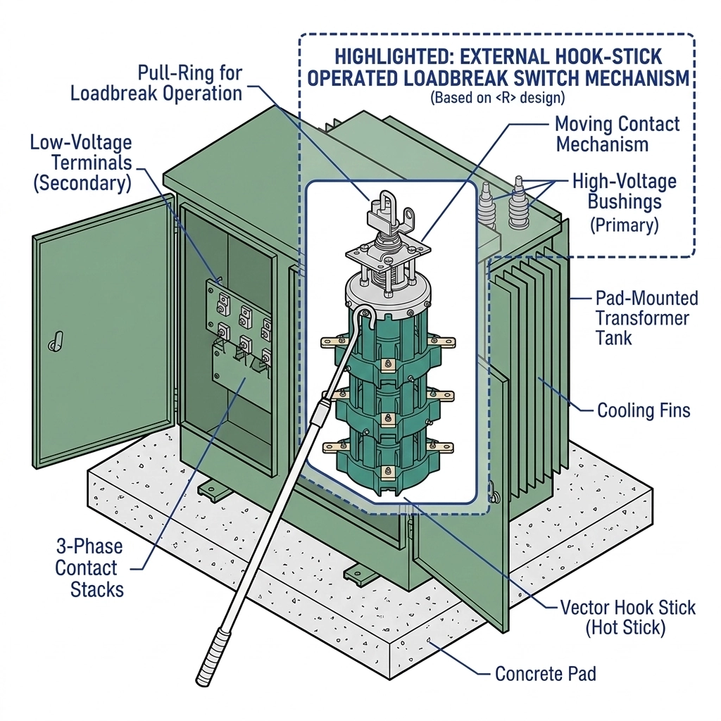
A interruptor limitador de carga is a transformer-mounted mechanical switching device engineered to safely make or break energized electrical circuits under rated load conditions. In medium-voltage distribution networks, these devices are typically mounted internally or externally on oil-filled transformers, allowing utility personnel to interrupt continuous load currents without requiring the de-energization of the entire upstream feeder circuit.
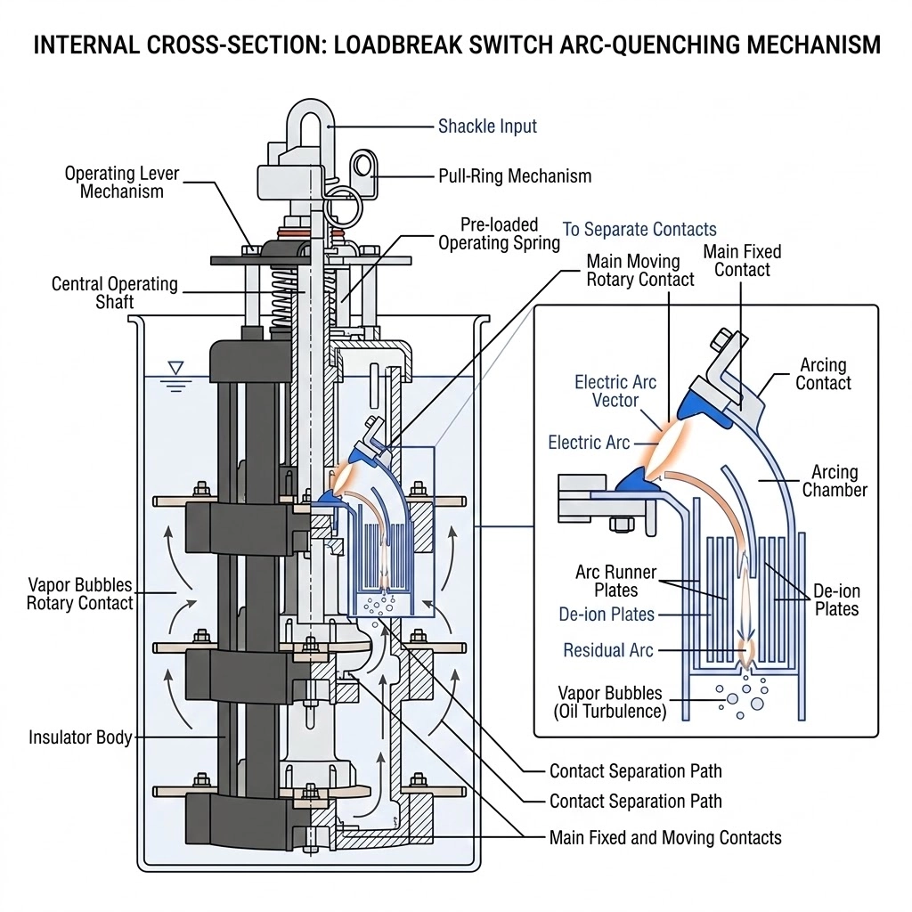
Figure 01:The internal spring-loaded kinematic assembly drives the copper-tungsten contacts apart, utilizing the surrounding dielectric oil to rapidly extinguish the electrical arc.
The Physics of Arc Interruption
The fundamental challenge of energized switching is managing the electrical arc that forms the exact moment the internal contacts separate. Unlike an off-circuit tap changer, a loadbreak switch must actively extinguish this high-temperature plasma arc. In pad-mounted distribution transformers, the switch relies on the surrounding dielectric medium—typically highly refined mineral oil or synthetic ester fluids—to cool, compress, and ultimately quench the arc channel.
To prevent severe dielectric degradation and contact erosion, the physical separation of the contacts must occur with extreme mechanical speed. The thermal energy (ΔT) and localized pressure generated by the arc must be contained, requiring the spring-loaded mechanism to quench the arc within a half-cycle to one full cycle (approximately 8.3 to 16.6 milliseconds at 60 Hz). If the arc duration extends beyond this extremely narrow window, the subsequent heating can cause rapid oil vaporization, risking catastrophic tank rupture.
Differentiating Make and Break Capabilities
Understanding the precise operational limits of these devices is vital for field reliability and operator safety. A standard distribution loadbreak switch is engineered to carry and interrupt continuous load currents, typically up to 630 A across 15/25 kV and 38/40.5 kV voltage classes.
However, it is necessary to distinguish between load-breaking and fault-interrupting capabilities. A loadbreak switch is not a circuit breaker. While it possesses a “fault-make” rating—meaning it is mechanically robust enough to be closed into a pre-existing short circuit without exploding—it cannot safely “break” or interrupt massive fault currents that may exceed 10,000 A. For true fault interruption, the switch must be coordinated with series protective devices like <a href="/es/””/">fusibles limitadores de corriente</a>. As outlined by [NEED AUTHORITY LINK SOURCE: IEEE standards for pad-mounted load-interrupting switchgear], rigorous testing protocols are required to verify these asymmetrical making and symmetrical breaking capacities before field deployment.
Structural Components and Operating Mechanisms
The internal architecture of a loadbreak switch is dictated by the extreme physical demands of interrupting medium-voltage circuits within a confined, oil-filled transformer tank. Unlike simple isolation links, these <a href="/es/””/">accesorios para transformadores</a> are precision-engineered kinematic assemblies designed to guarantee reliable and repeatable switching performance over decades of field service.
Stored-Energy Spring Mechanisms
The most important structural element of a loadbreak switch is its over-toggle, stored-energy spring mechanism. When a field operator rotates the external operating handle using a hot-stick, the internal rotary contacts do not immediately move. Instead, the mechanical input compresses a heavy-duty torsion or compression spring assembly.
Once the spring reaches its maximum compression threshold, it mechanically trips and releases its stored kinetic energy, driving the contact assembly open or closed at a velocity completely independent of the operator’s physical speed. This “quick-make, quick-break” action is an absolute requirement for energized switching. If the contacts were to separate slowly, the resulting electrical arc would persist, causing massive thermal degradation to the surrounding dielectric fluid. To prevent this, the spring mechanism forces the contacts apart at high mechanical velocities, typically between 3 m/s and 6 m/s, ensuring the arc is stretched and extinguished rapidly before dangerous hydrostatic pressure builds within the transformer housing.
Contact Architectures and Wear Resistance
To survive the extreme localized heating of arc interruption, loadbreak switch contacts are fundamentally designed to manage electrical wear. The contact architecture relies on specialized geometries and materials to carry continuous load while surviving transient switching arcs. The primary current-carrying surfaces are typically constructed from highly conductive silver-plated copper, designed to carry continuous rated currents up to 630 A with a strictly controlled temperature rise (ΔT ≤ 65°C above the ambient oil temperature).During an opening operation, the geometry ensures that the arc forms across dedicated sacrificial arcing zones rather than the primary conduction surfaces. These arcing zones must endure transient plasma temperatures that can easily exceed 10,000°C. To withstand this localized bombardment, the contact tips are often manufactured from sintered arc-resistant refractory metal alloys, such as copper-tungsten (CuW). This specialized material matrix severely limits contact erosion (often evaluated in μm per switching operation) and critically prevents the contacts from micro-welding together under severe fault-make conditions.
[Perspectiva del experto]
Spring mechanism failure is often linked to operator hesitation or “teasing” the handle during manual actuation, rather than pure mechanical fatigue of the internal coils.
Oil dielectric strength directly correlates with contact lifespan; contaminated oil or elevated moisture drastically accelerates CuW tip erosion during routine load dropping.
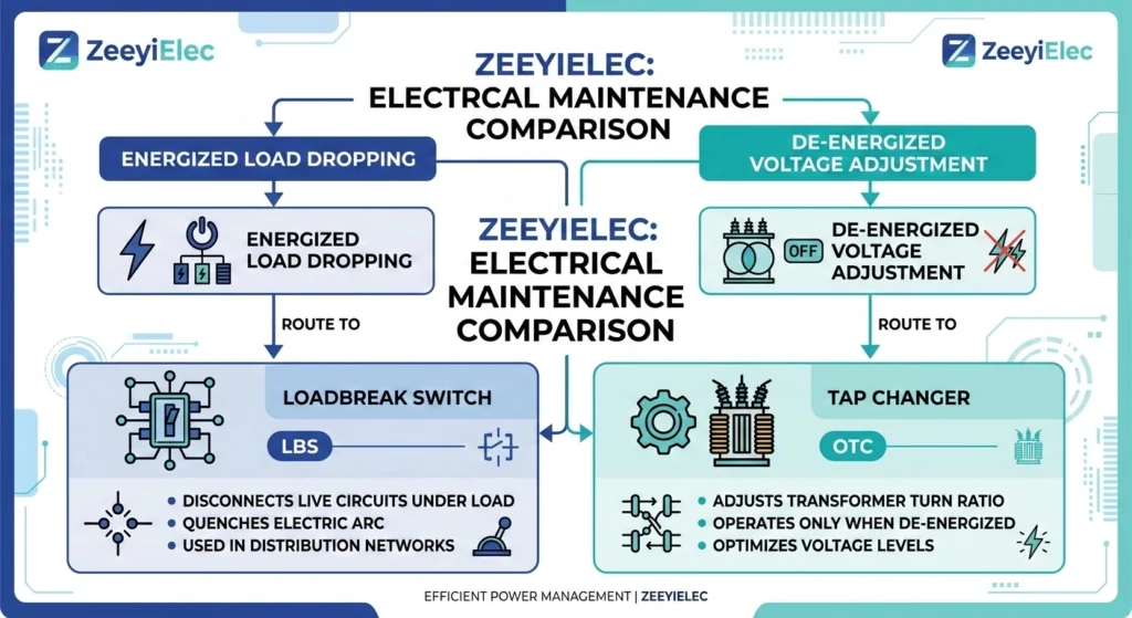
Establishing the Application Boundary: Energized vs. De-Energized Switching
A frequent point of confusion in field operations and procurement is the functional overlap between switching devices. Both loadbreak switches and cambiadores de tomas fuera de circuito appear on distribution transformers, involve mechanical switching actions, and mount externally with handles or motor operators. However, a single operational distinction—energized versus de-energized operation—defines the absolute application boundary between these two components.
Figure 02:Operational safety boundary matrix delineating energized load dropping capabilities from strictly de-energized voltage ratio adjustments.
Safe Energized Operation Limits
A loadbreak switch interrupts current while the transformer stays energized. Field crews rely on these switches to isolate network sections without blacking out entire feeder lines. Before actuating the switch, operators must verify that the circuit current falls within the device’s certified limits—typically 630 A continuous for 15 kV to 35 kV distribution systems.
Conversely, an off-circuit tap changer adjusts voltage ratio only after the transformer is de-energized. It physically lacks the stored-energy mechanisms and arc-quenching structures required to extinguish high-energy plasma.
The Consequence of Misapplication on the Grid
The confusion between these two accessories carries severe real-world consequences. Operating an off-circuit tap changer (typically rated for 63 A or 125 A) under active load physically destroys the device. Because it separates contacts slowly based on the operator’s manual turning speed, breaking a load current of even ≥ 10 A will draw a sustained electrical arc. This unmanaged arc rapidly degrades the surrounding dielectric oil, severely damages the copper contacts, and risks catastrophic internal transformer faults.From an engineering specification standpoint, specifying a loadbreak switch where voltage adjustment is actually needed simply leaves the core problem unsolved. Field engineers must clearly delineate these application boundaries during the initial RFQ phase to prevent safety hazards and ensure the correct accessory is deployed for the correct grid task.
Configurations in Distribution Transformers: Two-Position vs. Four-Position
When specifying a loadbreak switch for a pad-mounted transformer, engineers must select the internal contact configuration based on the broader distribution system topology. The choice directly impacts grid resilience, fault isolation capabilities, and overall project cost. Under established industry standards such as IEEE C57.12.34—which governs the electrical and mechanical requirements for three-phase pad-mounted distribution transformers—utilities typically deploy either two-position or four-position switching schemes.
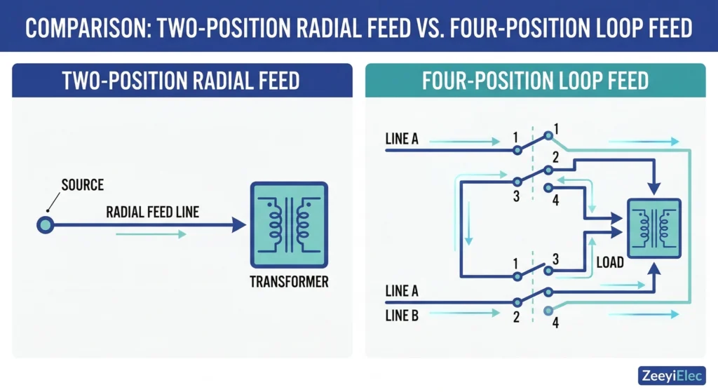
Figure 03:Single-line distribution schematic illustrating a basic two-position radial endpoint versus a highly resilient four-position loop feed sectionalizing node.
Two-Position Radial Feed Applications
A two-position loadbreak switch provides a simple, binary operational state: On (closed) or Off (open). This configuration is almost exclusively utilized in radial feed distribution networks, where a single power source supplies the transformer at the end of a line. In these setups, the incoming underground power is typically terminated using reliable accesorios para cables (such as cold shrink or heat shrink terminations) that connect directly to the switch’s primary bushings.
While highly economical, the radial topology means that any upstream fault or maintenance operation will inevitably result in a complete power outage for the downstream load. The standard rating for a two-position configuration handles continuous currents (Ic) of 200 A or 630 A at 15/25 kV system voltages, depending on the specific transformer kVA rating and load demands.
Four-Position Loop Feed Sectionalizing
For high-demand infrastructure and residential subdivisions requiring elevated reliability, utilities utilize loop feed networks. A four-position sectionalizing loadbreak switch is specifically engineered for this advanced topology. It allows operators to route power from two distinct primary sources (Line A and Line B) within the same underground loop.
The switch operates with an internal V-blade or T-blade contact mechanism, providing four distinct operational states: Line A connected, Line B connected, Both lines connected (loop closed), or Both lines open. If a fault occurs on Line A, the operator can safely isolate the damaged cable section and immediately restore power to the transformer via Line B, drastically minimizing outage duration.
Configuration Comparison Matrix
Loadbreak Switch Configuration Comparison
[Perspectiva del experto]
Four-position switches represent a higher upfront cost but often pay for themselves during the first major cable fault by maintaining loop integrity and isolating the outage.
Always verify the physical dimensions of the transformer tank; a four-position switchgear assembly requires a significantly larger internal footprint and oil volume than a basic two-position switch.
Field Deployment and Operational Safety Protocols
Operating medium-voltage equipment inherently involves managing immense electrical energy. While the internal stored-energy mechanism guarantees the quick-action separation of contacts, the safety of the field personnel ultimately relies on strict adherence to established switching sequences and physical verification protocols. A loadbreak switch is designed to handle energized load dropping, but it must be operated within its intended environmental and structural boundaries.
Hook-Stick Operation Best Practices
Most pad-mounted transformer loadbreak switches are designed specifically for external hook-stick operation. This design allows the operator to maintain a safe physical distance from the equipment during the make or break action, mitigating the risk of exposure to potential arc-flash events.
When executing a switching order, linemen typically use an insulated fiberglass hot-stick, often ranging from 8 to 12 feet in length. The operator must position themselves completely outside the direct blast trajectory of the transformer doors. Although the internal spring dictates the actual contact velocity, the operator must deliver a firm, decisive pull or rotation to the switch’s external eyelet. Hesitation can cause the spring to partially charge without fully tripping, potentially leaving the switch in an unsafe, intermediate state. Once the spring releases, a distinct mechanical impact sound confirms the toggle has completed its travel.
Oil Level and Dielectric Verification Before Switching
Before executing any switching operation, field personnel must visually confirm the transformer’s fluid level and temperature gauges. Because the loadbreak switch relies entirely on the dielectric strength of the surrounding oil to extinguish the high-temperature arc, the physical condition of this fluid is non-negotiable. Standard electrical mineral oil typically requires a minimum dielectric breakdown voltage of ≥ 30 kV across a standard 2.5 mm test gap to safely support a 630 A load break.If the internal fluid level drops below the manufacturer’s safe minimum indicator at an ambient 20°C, the upper switch contacts may become exposed to the nitrogen blanket or air space at the top of the tank. Operating the switch in this compromised state removes the essential cooling and arc-quenching medium. The resulting unmanaged electrical arc can instantly generate localized gas temperatures exceeding 5,000°C, causing rapid internal pressure buildup and creating the immediate potential for a catastrophic enclosure rupture.
Specifying Loadbreak Switches for Your Next Project
Procuring the correct switching device requires precise alignment between the component’s mechanical capabilities and the operational demands of the distribution grid. An incomplete specification can lead to catastrophic field failures or costly installation delays.
Essential RFQ Parameters
When submitting a Request for Quotation (RFQ), engineers must define several mandatory electrical and structural parameters. First, specify the required system voltage class, which typically includes 15/25 kV or 38/40.5 kV options for pad-mounted distribution networks. Second, clearly state the continuous current rating; standard utility applications almost universally require a robust 630 A carrying capacity. Finally, identify the application scope by specifying whether the transformer is a 1-phase or 3-phase oil-filled unit, as this dictates the mechanical linkage and contact architecture of the switch.
Partnering with ZeeyiElec for Transformer Accessories
The ZeeyiElec loadbreak switch portfolio covers Two-Position and Four-Position Sectionalizing designs engineered for reliable switching in oil-immersed transformer systems. These components feature hook-stick operable mechanisms and stored-energy quick action suitable for both 1-phase and 3-phase applications. Whether you are upgrading a simple radial feed or designing a complex loop-feed grid, our team supports product selection, technical details, and quotation response for OEM/distributor projects.
Share your required specs, drawings, and target market with our engineering team—we’ll reply with technical feedback and quotation suggestions to keep your procurement cycle on schedule.
Preguntas frecuentes
Can a loadbreak switch interrupt a short circuit fault?
No, standard loadbreak switches are specifically engineered to interrupt rated continuous load currents—typically up to 630 A—rather than massive fault currents. They must be carefully coordinated with backup protection, such as current limiting fuses, to safely clear high-magnitude faults before catastrophic equipment damage occurs.
What is the typical voltage range for pad-mounted transformer loadbreak switches?
These switching devices are commonly deployed across medium-voltage distribution networks, safely operating within the standard 15/25 kV and 38/40.5 kV voltage classes. Their actual field capability depends heavily on being fully submerged in a suitable dielectric insulating medium, such as highly refined mineral oil, to prevent internal flashovers.
How does a four-position loadbreak switch differ from a two-position?
A two-position switch provides basic on/off control for a single radial feed, whereas a four-position switch delivers advanced sectionalizing capabilities for loop-feed systems. This structural difference allows utility operators to isolate specific faulted cable segments for maintenance while simultaneously maintaining continuous power to downstream loads.
Why use a hook-stick to operate a loadbreak switch?
A hook-stick provides essential physical distance for operators working with energized, pad-mounted equipment, keeping them safely outside the immediate arc-flash boundary. It also provides the necessary mechanical leverage to properly actuate the switch’s internal stored-energy spring mechanism, ensuring a rapid, quick-action contact separation.
Can I use a loadbreak switch to adjust transformer voltage?
No, adjusting the voltage turns ratio is the specific, dedicated function of an off-circuit tap changer, which must only be operated when the transformer is completely de-energized. Specifying a loadbreak switch where voltage adjustment is actually needed leaves the core problem unsolved and creates dangerous operational confusion in the field.
yoyo shi
Yoyo Shi escribe para ZeeyiElec, centrándose en accesorios de media tensión, componentes de transformadores y soluciones de accesorios para cables. Sus artículos cubren aplicaciones de productos, fundamentos técnicos y perspectivas de abastecimiento para compradores de la industria eléctrica mundial.