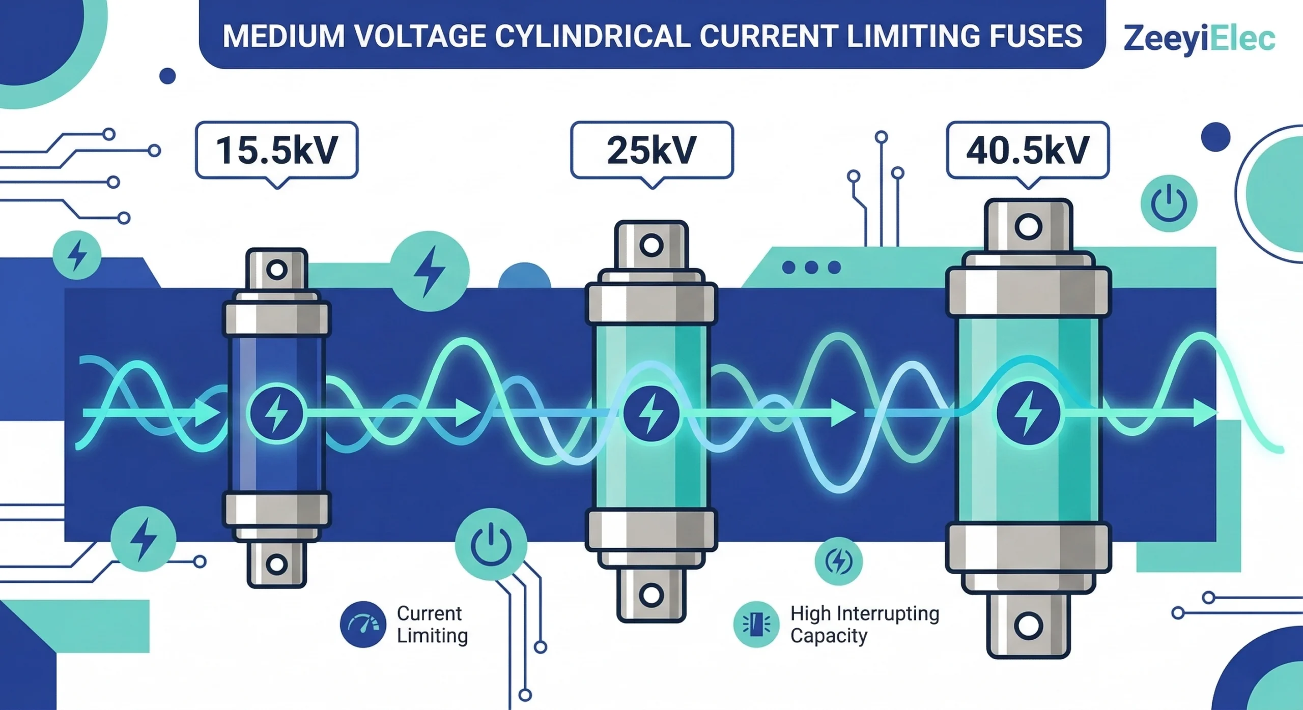
Introducción a los fusibles limitadores de corriente de media tensión
Al especificar accesorios para transformadores En las redes de distribución, los ingenieros deben tener en cuenta corrientes de fallo de varios órdenes de magnitud. Un fusible limitador de corriente está diseñado para interrumpir corrientes de fallo elevadas antes de que alcancen picos destructivos. En los sistemas de protección de transformadores, ayuda a reducir la tensión térmica y mecánica del equipo. Para seleccionar el fusible adecuado en las clases de tensión de 15,5kV, 25kV y 40,5kV es necesario conocer no sólo los parámetros de la red eléctrica, sino también la física interna que permite que estos dispositivos funcionen de forma segura y eficaz.
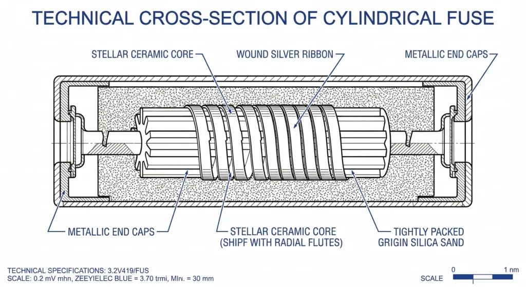
Figura 01: La arquitectura interna de un fusible limitador de corriente se basa en arena de sílice de gran pureza y una cinta de plata con muescas de precisión para forzar las corrientes de fallo a cero.
La física del apagado del arco
Los fusibles limitadores de corriente no se funden sin más, sino que fuerzan activamente a cero las corrientes de fallo mediante una reacción interna especializada.
En el interior de la carcasa sellada de fibra de vidrio o epoxi, un elemento de cinta de plata de alta conductividad (a menudo de pureza 99,9%) se enrolla alrededor de un núcleo estelar central, normalmente de cerámica. Este elemento presenta restricciones, o muescas, específicamente calibradas. Cuando se produce un fallo de gran magnitud, estas secciones restringidas se funden casi instantáneamente, normalmente con un tiempo de fusión ≤ 2 ms. La rápida vaporización de la plata crea un intenso arco eléctrico. El medio circundante, compuesto por arena de cuarzo y sílice de gran pureza, absorbe inmediatamente el calor extremo. La arena se funde y se fusiona con el vapor de plata para formar una sustancia altamente resistiva, similar al vidrio, conocida como fulgurita. Este rápido cambio de fase introduce una resistencia masiva (a menudo > 1 MΩ) en el circuito, forzando la corriente a cero antes de que la forma de onda natural de la corriente alterna alcance su pico, limitando eficazmente la energía máxima dejada pasar.
Diferencias estructurales entre clases de tensión
Aunque el mecanismo fundamental de extinción del arco es idéntico en todos los niveles de tensión, la arquitectura interna debe adaptarse para gestionar los distintos niveles de energía. Las tensiones más altas del sistema generan tensiones transitorias de recuperación (TRV) más altas en el fusible inmediatamente después de que se despeje el fallo. Para evitar que el arco vuelva a formarse, el fusible debe tener una resistencia dieléctrica suficiente.
Este requisito dicta la longitud física tanto del cuerpo del fusible como del elemento interno de plata. Por ejemplo, un fusible típico de 15,5 kV fusible limitador de corriente puede medir aproximadamente 359 mm de longitud total. Por el contrario, un fusible de 40,5 kV debe ser sustancialmente más largo, superando con frecuencia los 530 mm, para adaptarse a la distancia de extinción de arco necesaria. Además, la distribución granular de la arena de sílice y la geometría exacta de las muescas del elemento de plata se calibran de forma diferente para cada clase de tensión con el fin de optimizar la velocidad de formación de fulgurita y gestionar la energía térmica específica disipada durante la interrupción.
Comprensión de los límites de las clases de tensión (15,5kV, 25kV, 40,5kV)
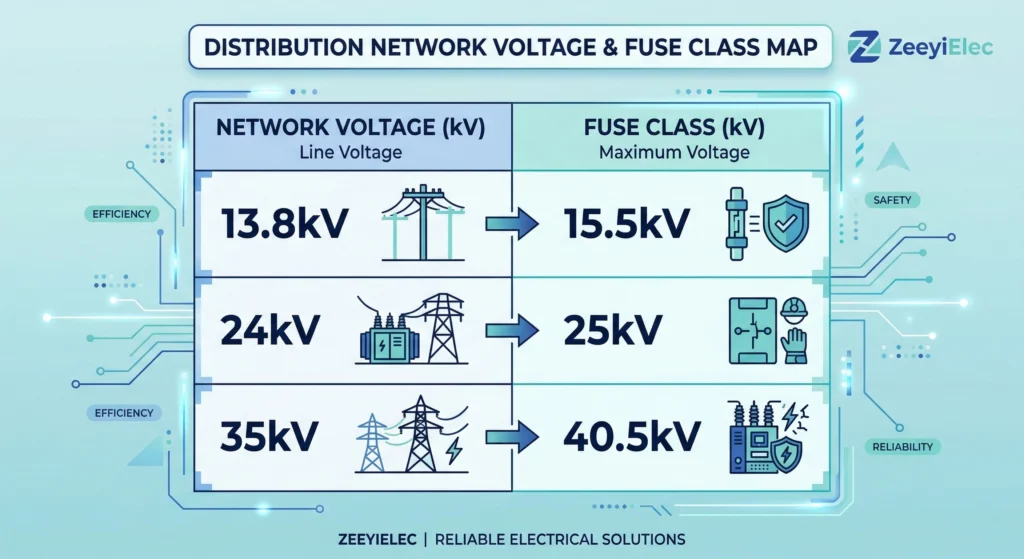
Seleccionar la clase de tensión adecuada para un fusible limitador de corriente no es una mera sugerencia; es un requisito dieléctrico estricto regido por normas internacionales. Según [NEED AUTHORITY LINK SOURCE] (texto de anclaje: marcos de pruebas IEC 60282-1 e IEEE C37.41), la tensión máxima de diseño de un fusible siempre debe ser igual o superior a la tensión máxima de funcionamiento de línea a línea del sistema. Aplicar un fusible de 15,5 kV a un circuito de 25 kV provocará un fallo catastrófico durante un fallo, ya que el fusible no puede generar suficiente tensión de arco para contrarrestar la tensión transitoria de recuperación del sistema. A la hora de especificar, los ingenieros deben verificar si la conexión del transformador es de línea a tierra o de línea a línea, ya que esto dicta la tensión precisa que experimentará el fusible.
Figura 02: La selección correcta del fusible requiere que la tensión máxima de diseño del fusible coincida con la tensión nominal de funcionamiento de línea a línea del sistema para evitar descargas disruptivas.
Tensión nominal del sistema
Tensión máxima de diseño del fusible
Resistencia típica BIL
≤ 13,8 kV
15,5 kV
95 kV
≤ 24 kV
25 kV
125 kV
≤ 35 kV
40,5 kV
200 kV
Aplicaciones de 15,5 kV
La clase de fusible de 15,5 kV es el componente básico de las redes de distribución urbanas estándar. Se especifica principalmente para redes de 12 kV y 13,8 kV. En estos entornos, suelen integrarse junto con Conjuntos de fusibles Bay-O-Net diseñados para la protección de transformadores de distribución llenos de aceite. Esta combinación crea un esquema de protección fiable y de rango completo para equipos montados en pedestal.
Aplicaciones de 25 kV
La categoría de 25 kV (a menudo denominada 27 kV en los mercados ANSI) da servicio a sistemas de distribución de 20 kV a 24 kV. Este nivel es muy frecuente en polígonos industriales y extensiones de distribución rural, donde las compañías eléctricas aumentan la tensión para reducir las pérdidas en las líneas en distancias de transmisión más largas. La actualización de una red de 15kV a 25kV requiere unas dimensiones de fusibles totalmente nuevas para evitar descargas disruptivas.
Aplicaciones de 40,5 kV
Los fusibles de la clase de 40,5 kV están diseñados para redes de 33 kV y 35 kV de gran potencia. Suelen encontrarse en aplicaciones de reducción de subestaciones primarias, explotaciones mineras y sistemas de colectores de energía renovable a gran escala, como parques eólicos y solares. Dado que la energía potencial de fallo en este nivel de tensión es inmensa, los fusibles de 40,5 kV presentan las dimensiones físicas más largas y los mayores volúmenes de arena de sílice para maximizar la absorción térmica y garantizar que el fallo se elimina en medio ciclo.
[Expert Insight: Limitaciones dimensionales en las adaptaciones a posteriori].
Desajustes físicos: No es posible introducir un fusible limitador de corriente de 25 kV en una caja de interruptores de 15,5 kV. La mayor longitud necesaria para la extinción de arcos de 25 kV suele superar la distancia existente entre clips.
Violaciones de la autorización: Incluso si se modifican los herrajes de montaje, la actualización de la clase de tensión sin sustituir la envolvente puede violar las distancias dieléctricas de fase a fase o de fase a tierra.
Actualizaciones sistemáticas: Siempre verifique que los casquillos, los separadores y el aislamiento circundante tengan una clasificación similar para el BIL más alto cuando actualice las clases de tensión de los fusibles.
Parámetros de especificación clave para la selección de fusibles
La selección de accesorios para transformadores exige ajustar varios parámetros simultáneamente para garantizar la fiabilidad a largo plazo. Ir más allá de la clase de tensión de referencia implica una evaluación rigurosa de la capacidad de carga térmica del fusible y de su capacidad de eliminación de fallos.
Corriente continua y límites de precarga
La corriente continua nominal (In) define la carga máxima en estado estacionario que el fusible puede soportar continuamente sin sobrepasar sus límites de aumento de temperatura. Al dimensionar este parámetro, los ingenieros suelen seleccionar un fusible con un valor nominal de 140% a 200% de la corriente continua máxima a plena carga del transformador. Este amortiguador evita que el elemento de plata interno experimente fatiga térmica durante las sobrecargas temporales permitidas del sistema. Si la corriente continua se especifica demasiado cerca de la carga de funcionamiento normal, el fusible entrará prematuramente en su fase de predescarga, lo que provocará fusiones molestas e interrupciones innecesarias del suministro eléctrico.
Requisitos de capacidad de interrupción (I1)
La capacidad máxima de interrupción, comúnmente denominada I1, representa la corriente de falta simétrica prospectiva más alta que el dispositivo puede interrumpir de forma segura sin que se produzca un fallo estructural. Durante una falta atornillada, las corrientes pueden alcanzar decenas de miles de amperios en milisegundos. Por lo tanto, la I1 debe ser superior a la corriente de cortocircuito máxima disponible en el nudo de la instalación. Por ejemplo, los fusibles limitadores de corriente estándar de 15,5 kV suelen tener una I1 de 50 kA, mientras que los modelos físicamente más grandes de 40,5 kV pueden ofrecer capacidades de interrupción de 31,5 kA a 40 kA, dependiendo del volumen interno de arena de sílice y del diseño del elemento.
Adaptación de la característica tiempo-corriente (TCC)
Las curvas características de tiempo-corriente (TCC) son la herramienta definitiva para la coordinación de la protección. Estos gráficos logarítmicos representan el tiempo mínimo de fusión del fusible frente a la corriente de defecto prevista. Los ingenieros deben verificar que la curva TCC del fusible se sitúa con seguridad por encima del perfil de corriente de irrupción del transformador.
En las aplicaciones de campo, las corrientes de arranque transitorias durante la energización del transformador pueden alcanzar entre 10× y 12× la corriente a plena carga durante aproximadamente 0,1 segundos. Si la curva de fusión mínima del fusible se cruza con este perfil de irrupción, el elemento sufrirá tensiones mecánicas acumulativas, lo que conducirá inevitablemente a un fallo en campo [VERIFICAR NORMA: Directrices IEEE C37.47 para la coordinación de fusibles de distribución].
Además, el preciso mapeado TCC garantiza que el fusible funcione sin problemas con otros dispositivos de protección. Por ejemplo, al integrar fusibles en aparamenta equipada con un interruptor limitador de carga, El fusible debe eliminar los fallos graves mucho antes de que se comprueben los límites de resistencia mecánica del interruptor.
Condiciones de campo y reducción de potencia ambiental
Los fusibles limitadores de corriente no funcionan en el vacío; su rendimiento está fundamentalmente ligado al entorno físico del lugar de instalación. El diagnóstico sistemático de fallos sobre el terreno aísla las causas fundamentales antes de que se repitan los fallos. Siguiendo un flujo de trabajo estructurado, los ingenieros identifican qué falló realmente, por qué falló y qué condiciones permitieron que se produjera el fallo. A menudo, descubren que la fusión molesta no es un defecto de fabricación, sino más bien un fallo al no tener en cuenta las tensiones ambientales localizadas.
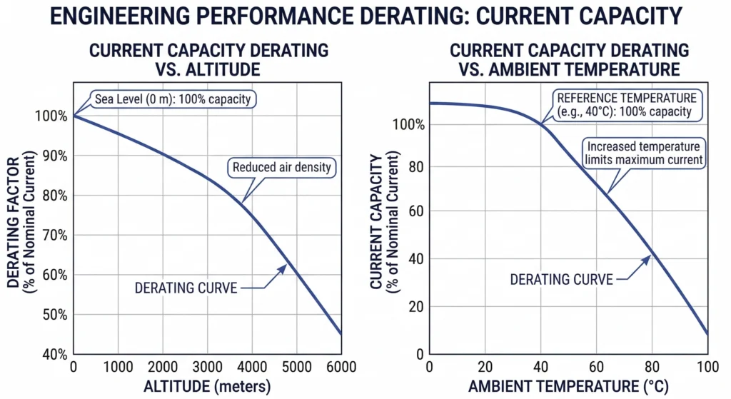
Figura 03:La capacidad de corriente continua debe reducirse para instalaciones que superen los 1.000 metros de elevación o los 40°C de temperatura ambiente del recinto.
Factores de corrección de altitud
La densidad del aire disminuye a medida que aumenta la elevación, lo que compromete directamente la capacidad de refrigeración convectiva de la carcasa del fusible. Para instalaciones situadas a elevaciones ≥ 1.000 metros sobre el nivel del mar, ya no se aplican los modelos de disipación térmica estándar. Una práctica fiable de ingeniería de campo es reducir la capacidad de transporte de corriente continua en aproximadamente 1,0% a 1,5% por cada 100 metros por encima de este umbral de 1.000 metros. Si no se aplica este factor de corrección por altitud, el elemento de plata interno funcionará a una temperatura significativamente superior a la que permiten sus parámetros de diseño, acelerando la fatiga térmica y desplazando prematuramente la curva tiempo-corriente.
Restricciones de temperatura ambiente del recinto
El microclima que rodea al fusible es igualmente crítico. En las aplicaciones de campo, especialmente en transformadores compartimentados montados en pedestal o en cámaras subterráneas mal ventiladas, la temperatura ambiente rara vez se mantiene en unos 20 °C teóricos. La radiación solar directa sobre una envolvente metálica, combinada con el calor generado por el núcleo del transformador y los fusibles adyacentes, hace que la temperatura ambiente sea muy baja. accesorios para cables que dirigen la energía hacia la unidad, pueden elevar las temperaturas del aire localizado por encima de 65°C. La resolución de problemas sobre el terreno de operaciones prematuras de fusibles de 15,5kV y 25kV apunta con frecuencia a este atrapamiento térmico exacto.
Cuando la temperatura ambiente que rodea a las pinzas fusibles supera los 40 °C, los ingenieros deben aplicar un factor de reducción de potencia secundario, que normalmente reduce el valor nominal de corriente continua entre 0,2% y 0,5% por cada 1 °C de aumento de temperatura (ΔT) por encima de los 40 °C de referencia. Si se instala un fusible de 40,5 kV en una subestación compacta de colectores de energías renovables sin realizar estos cálculos, la tensión térmica acumulada provocará inevitablemente la apertura del elemento en condiciones normales de carga. Una reducción de potencia ambiental adecuada es la única forma de garantizar que el fusible funcione estrictamente según lo previsto.
[Visión experta: Diagnóstico de operaciones molestas]
Comprueba la cronología: Si un fusible se funde repetidamente durante la parte más calurosa de la tarde de verano en lugar de durante el arranque con carga pesada, el atrapamiento térmico dentro de la caja es el culpable probable.
Examine la fusión: Un elemento que se funde estrictamente en el centro sin formar una fulgurita masiva suele indicar una fatiga térmica prolongada de bajo nivel y no un cortocircuito de gran magnitud.
Intervenciones de ventilación: La mejora de las rejillas pasivas o la adición de refrigeración activa a los armarios de distribución a menudo resuelve las operaciones de fusibles fantasma sin necesidad de recalcular todo el esquema de protección.
Coordinación con fusibles de reserva y expulsión
En las redes de distribución prácticas, confiar en un único dispositivo de protección para gestionar todas las situaciones de fallo posibles suele ser inviable desde el punto de vista eléctrico y económico. La experiencia de campo en numerosas instalaciones de subestaciones y transformadores montados en pedestal demuestra que la protección de rango completo requiere un sistema de dos fusibles cuidadosamente calibrado para gestionar las condiciones de funcionamiento del mundo real.
Estrategia de protección con dos fusibles
La protección de transformadores exige dos tecnologías de fusibles diferentes porque estos sistemas se enfrentan a corrientes de fallo que abarcan tres órdenes de magnitud. Durante el funcionamiento normal, las corrientes de carga se miden en decenas o centenares de amperios. La protección de transformadores requiere dos tecnologías de fusibles que funcionen en secuencia: Los fusibles Bay-O-Net eliminan las faltas de baja a moderada intensidad hasta aproximadamente 3.500 amperios, mientras que los fusibles limitadores de corriente interrumpen las faltas de alta magnitud que superan este umbral en medio ciclo.
Las instalaciones de campo ponen de relieve la naturaleza crítica de este emparejamiento. Si un fusible de expulsión estándar se ve sometido a un fallo atornillado de 20 kA a 50 kA, la rápida expansión del gas puede romper el portafusibles y expulsar violentamente aceite ardiendo. Por el contrario, un fusible limitador de corriente de reserva es físicamente incapaz de despejar con seguridad sobrecargas leves de baja magnitud (por ejemplo, un consumo sostenido de 150 A en un elemento nominal de 50 A). Si se ve obligado a interrumpir una falta por debajo de su intensidad mínima de corte (I3), el elemento de plata se fundirá, pero la corriente no será suficiente para formar una fulgurita. Esto provoca la formación continua de arcos, el desbordamiento térmico y el fallo catastrófico de la carcasa de epoxi dentro del depósito del transformador.
Coincidencia de puntos de cruce
La transición entre estos dos dispositivos se conoce como punto de cruce, y debe trazarse meticulosamente en un gráfico de características de tiempo-corriente (TCC). Esta lógica de coordinación crea una protección continua en todo el espectro de corrientes de defecto.
Cuando se diseña un paquete de transformadores de 25 kV o 40,5 kV, la lógica de coordinación dicta que la curva de fusión mínima del fusible limitador de corriente debe cruzarse con la curva de despeje máximo del fusible de expulsión en una magnitud de corriente específica. Por ejemplo, en una instalación típica de 15,5kV y 1000 kVA, este punto de cruce está estrictamente definido. Para cualquier corriente de defecto ≤ 3.500 A, el fusible de expulsión funciona solo. Para cualquier corriente de falta ≥ 3.500 A, el fusible limitador de corriente se funde más rápidamente, asumiendo el proceso de interrupción [VERIFICAR NORMA: Directrices IEEE C37.48 para la aplicación y coordinación de fusibles].
Durante la puesta en servicio, los técnicos de campo deben verificar que los fusibles de repuesto especificados se adhieren estrictamente a este estudio de coordinación original. La instalación de un eslabón de expulsión con una capacidad nominal incorrecta durante el mantenimiento rutinario puede desplazar, sin saberlo, el punto de cruce, creando un peligroso punto ciego de protección en el que ninguno de los fusibles puede despejar con seguridad un fallo de nivel medio.
Soluciones y adquisición de fusibles limitadores de corriente ZeeyiElec
Nuestra matriz de fusibles MV
Con sede en Wenzhou, la capital eléctrica de China, ZeeyiElec diseña y fabrica una completa cartera de fusibles limitadores de corriente de media tensión diseñados para su integración en transformadores de distribución rellenos de aceite. Nuestra matriz de producción cubre las principales clases de tensión necesarias para proyectos industriales y de servicios públicos en todo el mundo. Para aplicaciones estándar de montaje en pedestal, nuestra serie de 15,5 kV ofrece capacidades de interrupción de hasta 50 kA. Para redes de distribución de nivel superior, nuestras series de 25 kV y 40,5 kV están calibradas para despejar con seguridad las averías en entornos de trabajo pesado, proporcionando I1 de 31,5 kA a 40 kA. Cada unidad utiliza arena de sílice de gran pureza y elementos de plata con muescas de precisión para garantizar tiempos de limpieza de medio ciclo (a menudo ≤ 8 ms) y una formación estable de fulgurita.
Solicitar una evaluación técnica
Especificar el fusible correcto requiere algo más que seleccionar una tensión nominal. Nuestro equipo de ingeniería ofrece configuraciones OEM/ODM completas y adaptación técnica de modelos para su esquema de protección específico. Cuando envíe una petición de oferta, indique la corriente de carga continua de su transformador, los puntos de cruce requeridos de la característica tiempo-corriente (TCC) y las condiciones específicas de temperatura ambiente del recinto (especialmente si funciona a ≥ 40 °C). Proporcionamos información técnica rápida y documentación de exportación completa para garantizar que sus accesorios pasen la aduana sin problemas y lleguen a tiempo.
Preguntas frecuentes
¿Puedo utilizar un fusible de 25 kV en un sistema de 15 kV?
Sí, utilizar un fusible de clase de tensión superior (como 25 kV en una red de 15,5 kV) está técnicamente permitido y a menudo se hace para consolidar el inventario. Sin embargo, suele dar lugar a una tensión de arco más alta durante la interrupción de la falta, lo que requiere verificar que el nivel básico de aislamiento a impulsos (BIL) del sistema puede soportar el pico de tensión momentáneo.
¿Qué hace que se funda un fusible limitador de corriente sin que se produzca un fallo?
La fusión molesta se produce generalmente cuando las temperaturas ambiente dentro del recinto del transformador son ≥ 40°C, o cuando las corrientes de irrupción transitorias repetitivas degradan el elemento de plata interno con el tiempo. La aplicación de una reducción térmica adecuada (a menudo de 0,2% a 0,5% por cada aumento de 1°C por encima de la línea de base de 40°C) y una adaptación precisa de la curva TCC evitan este fallo prematuro.
¿Cómo seleccionar el poder de corte de un fusible de 40,5 kV?
El valor nominal de interrupción debe superar la corriente de defecto simétrica máxima disponible en la ubicación específica del transformador, que suele oscilar entre 12 kA y 50 kA en las redes de distribución de media tensión. Los ingenieros deben calcular este umbral en función de la capacidad de la subestación aguas arriba y de la impedancia total de la línea que conduce al lugar de instalación.
¿Afecta la altitud al rendimiento del fusible limitador de corriente?
Sí, las instalaciones a elevaciones ≥ 1.000 metros experimentan una reducción de la eficiencia de la refrigeración convectiva debido al menor espesor del aire, lo que requiere una reducción de la corriente continua para evitar el sobrecalentamiento. Una regla general de ingeniería estándar es reducir la capacidad de corriente continua en aproximadamente 1,0% a 1,5% por cada 100 metros por encima del umbral inicial de 1.000 metros.
¿Cuál es la diferencia entre los fusibles limitadores de corriente de reserva y los de uso general?
Los fusibles de reserva están diseñados para interrumpir de forma segura sólo las corrientes de defecto de gran magnitud y deben combinarse con un fusible de expulsión para eliminar las sobrecargas de baja magnitud. Los fusibles de uso general pueden interrumpir tanto las sobrecargas de baja magnitud como las corrientes de defecto elevadas de forma independiente, aunque su arquitectura interna ampliada los hace físicamente más grandes y más caros.
¿Con qué frecuencia deben sustituirse los fusibles limitadores de corriente de MT?
Los fusibles limitadores de corriente son dispositivos sellados que no se degradan, con una vida útil típica que coincide con la del transformador (a menudo ≥ 25 años) a menos que funcionen para despejar un evento de fallo. Sin embargo, si un fusible de expulsión funciona en un sistema coordinado de dos fusibles, es muy recomendable probar o sustituir el fusible limitador de corriente emparejado, ya que su elemento interno de plata puede haber experimentado una fusión parcial no detectable.
yoyo shi
Yoyo Shi escribe para ZeeyiElec, centrándose en accesorios de media tensión, componentes de transformadores y soluciones de accesorios para cables. Sus artículos cubren aplicaciones de productos, fundamentos técnicos y perspectivas de abastecimiento para compradores de la industria eléctrica mundial.