When a separable bushing well is specified simply as “epoxy,” that one word hides a range of formulations whose differences decide how the well performs across decades of service. This guide explains what epoxy actually is in a well body, how it behaves dielectrically, thermally, and mechanically, and where it sits among the material options — so the choice rests on engineering grounds rather than habit.
What a Bushing Well Is, and Why Material Choice Drives Its Performance
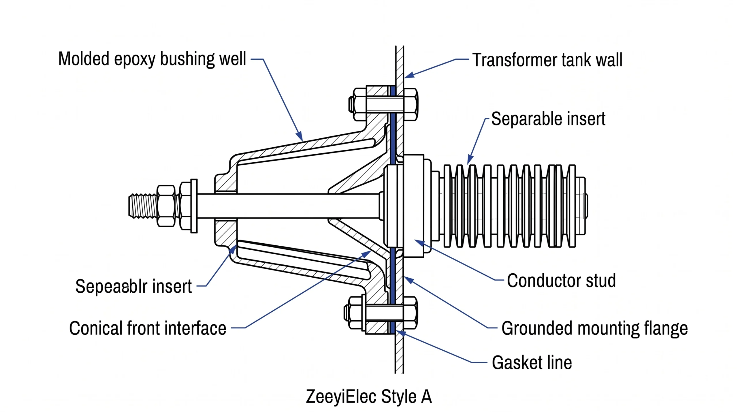
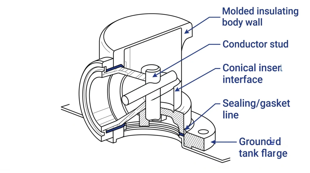
A bushing well is an insulated, tank-mounted interface permanently installed on a distribution transformer wall to receive a separable insert, elbow, or feed-through. It is the fixed half of a deadfront separable-connector system: the well stays bolted to the tank while the mating insert carries the cable connection and can be removed under safe conditions. The well has to do three things at once — seal the pressure boundary into the oil-filled tank, hold a stable dielectric path between the internal conductor stud and the grounded flange, and present a clean, repeatable seat for the insert.
Material choice is central because the well body is the insulation. Unlike a porcelain bushing where the shed profile dominates, a separable well relies on the molded body to manage the internal field, resist tracking at the front face, and survive the mechanical loading of insert insertion and extraction. Distribution wells are commonly specified at 15/25 kV and 15/25/35 kV classes at roughly 200 A continuous, and a correctly matched well and bushing well insert assembly is generally expected to share the transformer’s 25–40 year service life. So long-term aging behavior matters as much as the day-one rating. In field commissioning, the molded body rarely fails on its own; problems cluster at the conical interface where the insert seats, which is exactly why the body material — its tolerance for imperfect seating, contamination, and thermal movement — deserves close attention.
Cutaway of a separable epoxy bushing well identifying the conductor stud, molded insulating body, conical insert seat, gasket line, and grounded flange that jointly establish its dielectric path and sealed pressure boundary.
Epoxy Resin Chemistry: What “Epoxy” Actually Means in a Well Body
An epoxy system is a thermoset: a liquid resin is mixed with a curing agent (commonly an anhydride hardener) and mineral filler, then cast and cured into a rigid, cross-linked solid. Because the network sets during molding, the body is dimensionally stable and will not soften and re-flow the way a thermoplastic would. Two variables drive performance — the base resin and the filler.
Cycloaliphatic vs Bisphenol-A epoxy systems
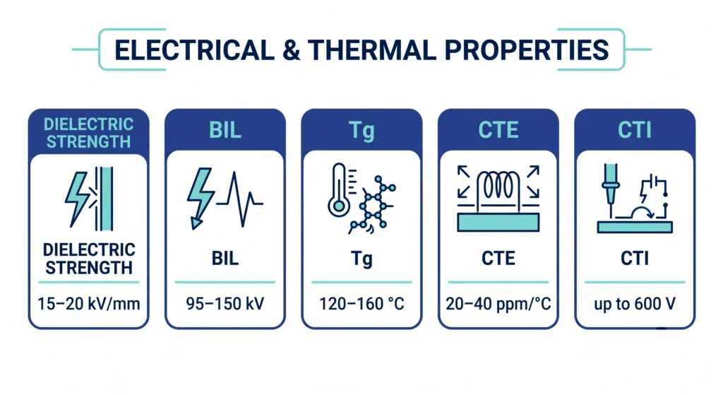
Bisphenol-A (DGEBA) systems are economical and mechanically strong but generally show weaker surface tracking and UV behavior, which limits exposed outdoor use. Cycloaliphatic epoxy is preferred for outdoor, tracking-critical interfaces because its surface erodes to a non-conductive residue rather than a carbonized track. A practical marker is the comparative tracking index (CTI): cycloaliphatic formulations typically reach the upper band, up to ~600 V, while many general-purpose resins sit well below. The trade-off is higher cost and tighter cure sensitivity, so a genuinely outdoor-rated well should name the resin family, not just “epoxy.”
Mineral fillers and why they matter
Filler is an engineering component, not an extender. Silica or alumina-trihydrate (ATH) fillers are loaded at roughly 55–65% by weight to manage thermal expansion, mechanical robustness, and arc/tracking resistance together. Filling pulls the coefficient of thermal expansion (CTE) down from the ~50–60 ppm per °C of unfilled resin toward roughly 20–40 ppm per °C — critical because the body shares an interface with brass hardware and rubber inserts that expand at different rates each thermal cycle. Filler also lifts the glass-transition temperature (Tg) into a typical 120–160 °C window. In observed field returns, cracking traces more often to thermal-cycle fatigue at filler-resin interfaces than to dielectric overstress, which makes filler quality and cure completeness worth checking during supplier qualification.
Epoxy Performance Notes: Dielectric, Thermal, and Mechanical Behavior
Epoxy earns its place by balancing several properties rather than maximizing any one. For distribution apparatus the governing reference is IEEE Std 386, which defines separable insulated connector systems — including bushing wells and inserts — across roughly 2.5–35 kV classes, setting the dielectric and interface expectations a compliant well is built to.
Epoxy Performance Snapshot
Property
Typical range (MV-grade epoxy)
Why it matters for a well
Intrinsic dielectric strength
15–20 kV/mm
Sets margin between conductor stud and grounded flange
Basic insulation level (BIL), 15–35 kV classes
95–150 kV
Survives lightning/switching impulse at the interface
Glass-transition (Tg)
120–160 °C
Keeps the body rigid across normal loading
CTE (filled)
20–40 ppm per °C
Limits interface gapping over thermal cycles
Comparative tracking index
up to ~600 V
Resists surface tracking on outdoor wells
Dielectric and partial-discharge behavior
The body’s job is field management, not just raw withstand. A sound interface keeps partial-discharge (PD) inception above operating stress, and factory PD testing — commonly to a few picocoulomb acceptance at a defined test voltage — is the practical screen for voids or poor cure. PD that appears only after installation usually points to the seated interface rather than the molded body, since the epoxy is tested before it ships. Treat the body rating and the assembled-interface rating as two separate questions.
Thermal and mechanical behavior
The thermal-class and CTE figures above carry the well through daily load cycling. With a filled CTE near 20–40 ppm per °C the body moves far less than unfilled resin, yet still expands at a different rate than the brass stud and rubber insert, so the gasket and seating geometry absorb the difference. Epoxy’s edge over porcelain is impact tolerance — it does not shatter from a dropped tool or rough handling during insert changes, which matters in cramped pad-mount enclosures. Its limitation is that epoxy is not self-healing: once a track or crack initiates it generally propagates, so material selection and PD screening up front outweigh any field repair.
Reference snapshot of medium-voltage epoxy properties, gathering intrinsic dielectric strength, basic insulation level, glass-transition temperature, filled thermal expansion, and comparative tracking index into one compact engineering view for material screening.
[Expert Insight] Acceptance screening before energization
Require a factory PD report (picocoulomb acceptance at the stated test voltage) and confirm it travels with the unit.
Confirm the resin family in writing — cycloaliphatic for any outdoor or polluted interface, not generic “epoxy.”
Verify the BIL of the well matches the system BIL for its 15/25 kV or 15/25/35 kV class.
Inspect molded surfaces for voids, flash, or under-cure tackiness before accepting a batch.
Where Epoxy Fits Among Bushing Well Material Options
Epoxy is the common default for modern separable wells, but treating it as automatic invites mismatches. The realistic body options are cast epoxy and porcelain, with molded elastomer designs appearing in specific connector formats. The selection question is rarely “which material is best” in the abstract — it is which best survives the specific voltage class, current duty, and environment of the project.
Epoxy vs porcelain
Attribute
Epoxy (cycloaliphatic)
Porcelain
Impact resistance
High — tolerates handling, seismic, tool strikes
Brittle — chips or shatters
Relative weight
~30–50% lighter
Heavier; higher tank-wall load
Outdoor tracking
Good (CTI up to ~600 V)
Excellent, inert glazed surface
Moisture/interface
Molded seating, forgiving seal
Rigid; gasket discipline critical
Typical MV coverage
15/25 kV and 15/25/35 kV at ~200 A
Comparable classes
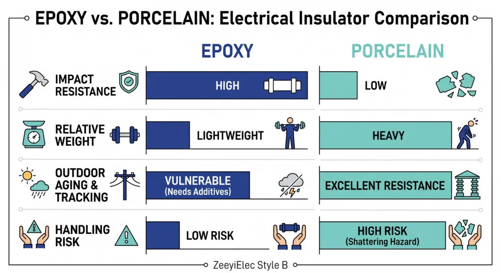
Across the 15/25 kV and 15/25/35 kV classes most wells occupy at roughly 200 A continuous, both materials meet the dielectric requirement. The differentiators are mechanical and logistical: epoxy’s lighter mass and impact tolerance cut damage during shipping and insert changes, while porcelain’s glazed surface still leads on long-term outdoor inertness on heavily polluted sites. The same logic carries into the wider medium-voltage bushing range, where porcelain and epoxy options coexist for these reasons.
Selection cues by environment and mounting constraint
Three field cues usually decide the call. First, handling and seismic risk: where inserts are swapped repeatedly in tight enclosures, epoxy’s impact tolerance is the practical advantage. Second, pollution and UV: a coastal or industrial site pushes toward cycloaliphatic epoxy specifically, or porcelain — not a general-purpose resin. Third, retrofit loading: adding or replacing wells on an existing tank favors epoxy’s lower mass, which reduces stress on the flange and gasket line. Underneath all three sits the non-negotiable step of matching rated class to system BIL and current duty before material preference enters — the same discipline laid out in this voltage-class selection guidance. Material choice optimizes a well that is already correctly rated; it cannot rescue one that is under-specified.
Side-by-side material trade-off between cycloaliphatic epoxy and porcelain bushing well bodies, weighing impact resistance, relative mass, outdoor aging behavior, and field handling risk for distribution transformer applications.
Field Conditions: How Epoxy Wells Behave Under Real Stress
Laboratory ratings describe a clean, correctly seated well at controlled temperature; service rarely offers those conditions. Most epoxy-well problems originate at the interface and the seal, not in the molded body. The patterns below come from commissioning and failure-return work and are offered as observations, not universal rules.
Moisture ingress and interface sealing realities
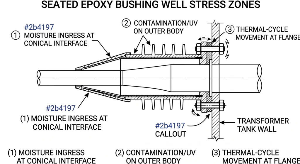
The most common finding is that moisture, not voltage, starts the failure sequence. When an insert is seated onto a contaminated or under-lubricated interface, or the mounting flange is left below its specified torque — often in the tens of N·m range per the manufacturer’s value — a micro-gap can admit moisture into the conical seat. In several cases, terminations that passed energization developed PD and tracking roughly 12–18 months later, after thermal cycling worked moisture deeper. The body epoxy was intact; the seated interface was the fault site, which is why interface cleaning and torque verification matter more than a rushed install suggests.
Contamination, UV, and tracking on outdoor installations
Outdoor wells live with pollution layers, salt fog, and UV, and here the resin family becomes visible in service: general-purpose resin wells on coastal and industrial sites have shown tracking and erosion sooner than cycloaliphatic units in comparable exposure, consistent with their lower tracking index. The hedged takeaway is that survival depends as much on specifying the right epoxy and keeping the surface clean as on the nameplate kV — a contaminated surface degrades actual withstand well below the catalog figure.
Thermal cycling, seating torque, and maintenance access
Daily load swings impose repeated thermal cycles; a typical distribution duty can drive interface temperature rises in the 40–60 °C range per cycle. Because epoxy, brass, and rubber expand at different rates, seating that was correct on day one can relax over years, so periodic re-inspection of separable interfaces is prudent. Epoxy’s impact tolerance helps — inserts can be exercised without porcelain’s shatter risk — but the real limit is access: a well that cannot be inspected in a tight enclosure tends not to be, and small interface issues are left to grow.
Field stress-point map of a seated epoxy bushing well, marking moisture ingress at the conical interface, surface contamination and ultraviolet exposure on the body, and thermal-cycle movement concentrated at the mounting flange.
[Expert Insight] Field inspection checklist for in-service wells
Re-verify mounting-flange torque against the manufacturer value at scheduled maintenance.
Clean and re-lubricate the conical interface before reseating any insert.
Look for surface tracking marks or chalking on outdoor bodies as an early-aging signal.
Prioritize wells in inaccessible enclosures for inspection — they are the ones most likely neglected.
Specifying Epoxy Bushing Wells for Your Project
Getting an epoxy well right is a specification exercise, not a material preference. The recurring lesson from RFQ review is that most mismatches trace to one or two parameters left blank, which forces a clarification loop before a quote can firm up. Locking the following before issuing the request removes that delay.
Spec-readiness checklist
Voltage class and BIL: confirm the 15/25 kV or 15/25/35 kV class and the matching system BIL the well must withstand.
Current duty: wells typically run ~200 A continuous — verify against actual load and fault duty, not nameplate convenience.
Interface standard: confirm the separable-connector interface (the IEEE 386 family) so well and insert mate physically and electrically.
Resin family and environment: specify cycloaliphatic epoxy for outdoor, UV-exposed, or polluted sites, and state the condition rather than implying it.
Mating insert compatibility: match the ampere class of the insert that seats into the well.
With those fixed, model matching is straightforward. ZeeyiElec’s engineering team supports class and interface verification across the full transformer accessories range, and can align well selection with the cable accessories terminating into the same network so the whole interface is specified together. Share your voltage class, current rating, interface standard, and site environment, and you will get a technical response and quotation suggestion rather than a generic catalog reply.
Frequently Asked Questions
What is a bushing well made of?
Well bodies are typically molded from epoxy resin or formed from porcelain, with epoxy now common on MV distribution interfaces because it pairs good dielectric performance with impact resistance; the exact choice depends on voltage class and outdoor exposure.
Is epoxy a good material for bushing wells?
Epoxy generally performs well across roughly 15–35 kV distribution classes thanks to high dielectric strength and mechanical toughness, though long-term outdoor results depend on the resin family and filler system rather than the word “epoxy” alone.
What temperature can an epoxy bushing well withstand?
Most MV-grade epoxy systems have a glass-transition temperature (Tg) around 120–160 °C, but continuous operating limits run well below that and vary with loading, ambient temperature, and the insert and gasket materials at the interface.
Epoxy vs porcelain bushing well — which is better?
Neither is universally better: epoxy offers lighter weight and far higher impact resistance, while porcelain offers long-proven outdoor aging, so the decision typically turns on environment, handling or seismic risk, and mounting constraints.
Does an epoxy bushing well degrade outdoors or under UV?
Cycloaliphatic epoxy formulations generally resist UV and surface tracking better than standard bisphenol-A types, but any outdoor well can age faster under heavy pollution, salt fog, or repeated wet-dry cycling without proper material selection.
What voltage and current ratings do epoxy bushing wells cover?
Distribution-class wells commonly span 15/25 kV and 15/25/35 kV at around 200 A continuous, though the usable rating always depends on the matched insert, system BIL, and installation conditions.
How long does an epoxy bushing well typically last?
A correctly specified and installed epoxy well can serve in the 25–40 year range alongside the transformer, but actual life depends heavily on interface sealing, contamination exposure, and maintenance practice.
yoyo shi
Yoyo Shi writes for ZeeyiElec, focusing on medium-voltage accessories, transformer components, and cable accessory solutions. Her articles cover product applications, technical basics, and sourcing insights for global electrical industry buyers.





 English
 한국어
한국어 العربية
 Español
 हिन्दी
 தமிழ்
தமிழ் Deutsch (Sie)
 Français
 Português do Brasil
 Русский