Shipping transformer or cable accessories across international borders involves more than booking freight; it requires a deep understanding of the technical documentation and the physical engineering behind the components. Among the most critical interface points in any power distribution system are the accessories that restore electrical insulation and manage stress fields.
Definition and Core Mechanics of Cold Shrink Technology
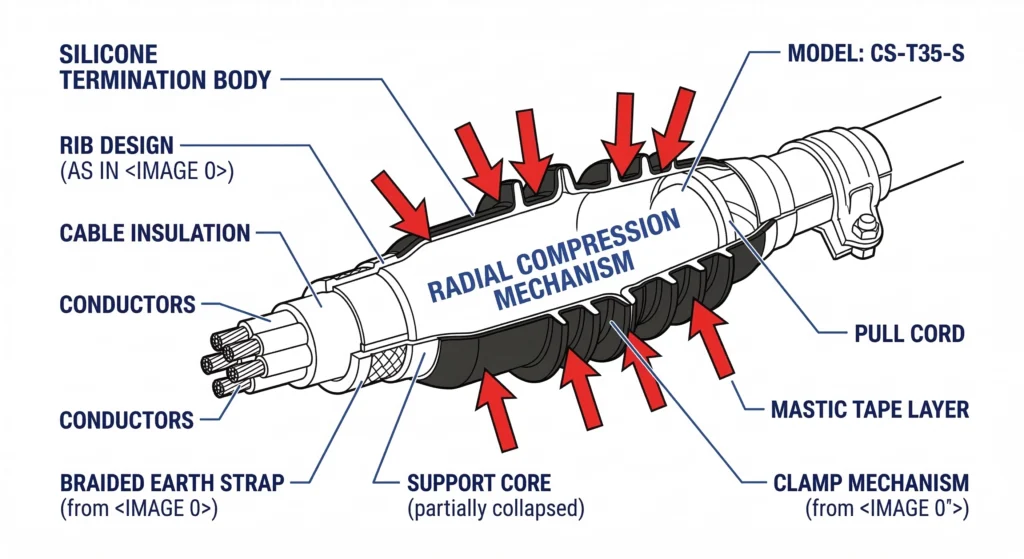
[FIG-01] Illustration of the “Active Pressure” seal mechanism where the silicone sleeve exerts constant radial force to prevent interfacial voids.
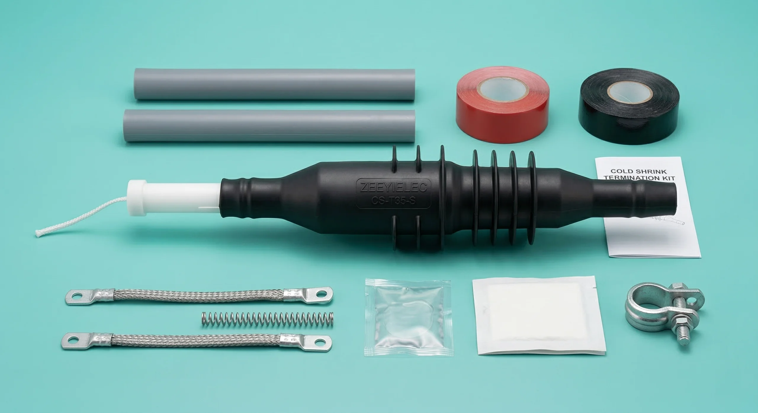
Cold shrink cable accessories are pre-expanded, engineered insulation components designed for medium-voltage cable systems, typically ranging from 8.7/15 kV to 26/35 kV. Unlike heat-shrinkable alternatives that require external thermal energy to trigger recovery, cold shrink technology relies on the inherent elastic memory of high-performance Liquid Silicone Rubber (LSR). The component is factory-expanded and loaded onto a removable, spiral-wound plastic support core. When this core is unwound during field installation, the sleeve collapses onto the cable interface, creating a permanent, high-pressure seal.
Defining Cold Shrink Components
At its core, a cold shrink kit consists of the insulation body, geometric or refractive stress control elements, and environmental sealing mastics. These cable accessories are engineered to restore the dielectric integrity of a cable after the factory layers have been stripped. The silicone material typically exhibits high dielectric strength, often exceeding 20 kV/mm.
The Living Seal: Material Memory and Constant Radial Pressure
The defining technical advantage is the “active” nature of the seal. Because the silicone is formulated to maintain a constant state of attempted contraction, it exerts continuous radial pressure on the cable. This is critical as power cables reach operating temperatures of 90°C and then cool; the cold shrink sleeve “breathes” with the cable, maintaining an interfacial pressure of approximately 0.05–0.15 MPa.
Comparison to Traditional Insulation Methods
Cold shrink eliminates the variability associated with torch temperature or tape tension. By providing a factory-defined insulation thickness and automated radial tension, this technology moves quality control from the field back to the manufacturing environment.
[Expert Insight: Material Longevity] * Chemical Stability: High-grade silicone resists UV degradation and chemical tracking better than standard polymers. * Elastic Recovery: Maintains the majority of its original radial pressure even after 20 years of thermal cycling. * Hydrophobicity: Naturally repels water, preventing conductive paths in high-humidity substation environments.
Technical Anatomy and Stress Management
The internal architecture of a cold shrink accessory is designed to solve the primary challenge of medium-voltage cable preparation: the concentration of electrical stress at the shield cutback. When the grounded semiconductor layer of a cable is removed, the electric field lines diverge sharply, creating a localized voltage gradient that can exceed the dielectric strength of air or standard insulation. Cold shrink components integrate specific material layers to manage this gradient, typically designed for system voltages up to 35 kV.
Geometric Stress Control Elements
The most critical feature is the stress relief patch. In high-quality cold shrink cable accessories, this component uses a geometric profile to gradually increase the distance between the conductor and the ground plane. Field experience shows that even a 1 mm deviation in positioning can result in premature dielectric breakdown.
High-Dielectric Constant (Hi-K) Layers
Many modern designs utilize refractive stress control through a High-Dielectric Constant (Hi-K) material layer. This material, with a relative permittivity ($\epsilon_r$) ranging from 15 to 30, acts as a buffer that refracts flux lines and smooths the potential distribution across the insulation interface.
Liquid Silicone Rubber (LSR) vs. EPDM
While early products utilized EPDM, the industry has shifted toward LSR for high-performance applications. LSR offers superior hydrophobic properties and maintains elasticity across a wider temperature range, ensuring the active pressure seal remains intact from -40°C to 130°C.
[VERIFY STANDARD: IEEE 404 Standard for Extruded and Laminated Dielectric Shielded Cable Joints]
Voltage Classes and Application Range
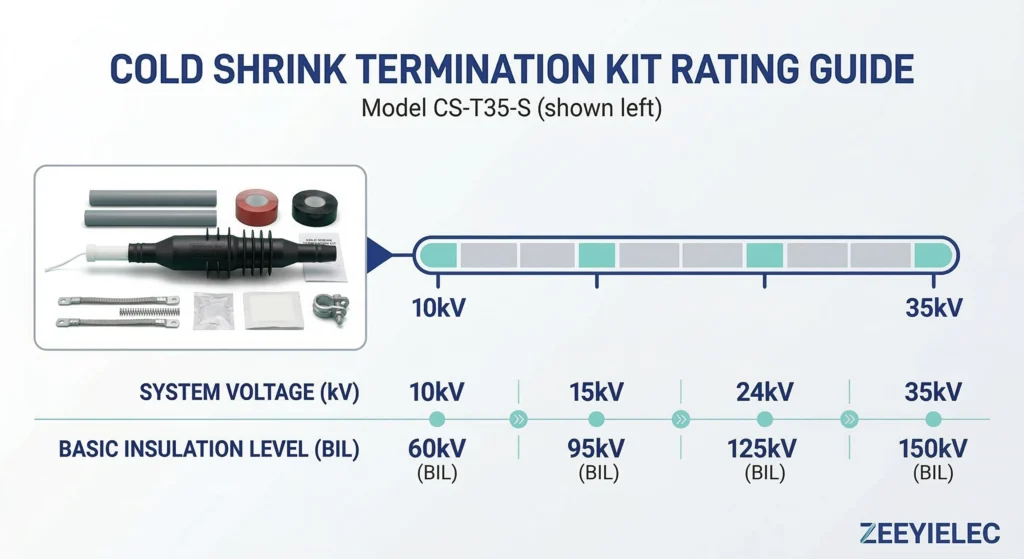
[FIG-02] Engineering reference chart showing the application spectrum of cold shrink accessories across 10kV, 15kV, 24kV, and 35kV distribution networks.
Cold shrink technology is engineered to cover the primary medium-voltage distribution spectrum, specifically supporting 10 kV and 35 kV class projects. Because the material properties of silicone allow for high dielectric strength, these accessories are applicable across a variety of power cable networks, including utility grids, industrial plants, and renewable energy installations. Selecting the correct voltage class is a non-negotiable step in the procurement process, as the insulation thickness and stress control lengths are precision-matched to the system’s BIL (Basic Insulation Level).
Medium Voltage Distribution (8.7/15kV to 26/35kV)
ZeeyiElec provides solutions for 8.7/15 kV and 26/35 kV classes. For a typical 35 kV system, the accessory is designed to meet a BIL of 150 kV or higher, ensuring the cold shrink cable accessories are not the weak link in the infrastructure.
Conductor Cross-Sectional Area Coverage
A significant advantage is “range-taking” capability. A single kit can accommodate multiple conductor sizes:
Small Range: 25–50 mm² for auxiliary feeds.
Standard Range: 70–240 mm² for typical feeders.
Large Range: 300–800 mm² for high-capacity industrial trunks.
Indoor vs. Outdoor Termination Configurations
The environment dictates the design. Indoor terminations are compact for switchgear, while outdoor versions include integrated “rain sheds” to increase creepage distance, preventing flashovers during wet conditions.
The Cold Shrink Installation Workflow
The reliability of cold shrink accessories is inherently tied to the precision of cable preparation before the core is even pulled. In my experience overseeing substation commissioning, over 90% of “infant mortality” failures in terminations are traced back to preparation errors rather than manufacturing defects. This workflow prioritizes the removal of contaminants and the exact positioning of the stress control interface to ensure the active pressure seal functions as intended across 10 kV to 35 kV systems.
Pre-Installation Cable Preparation
The process begins with stripping the cable to dimensions specified in the drawing. A critical field insight: the semiconductor layer must be removed using a peeling tool to ensure a smooth transition. Any nicks deeper than 0.1 mm can create air pockets that trigger partial discharge once energized.
Removing the Plastic Support Core
The sleeve is positioned over the cable end while still on its core. The installer pulls the leading edge of the plastic spiral, unwinding it counter-clockwise, allowing the silicone to collapse onto the cable shield cutback.
Ensuring Proper Overlap and Environmental Sealing
The sleeve must overlap the metallic shield for grounding. High-viscosity mastics are applied at the lug end and base to prevent moisture ingress.
Cold Shrink vs. Heat Shrink: Engineering Selection Framework
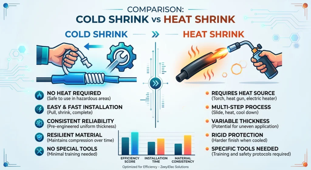
[FIG-03] Side-by-side comparison highlighting the safety and speed advantages of tool-free cold shrink installation compared to heat shrink methods requiring open flames.
Selecting between cold shrink and heat shrink technologies is not a matter of identifying a “superior” product, but rather matching the accessory to the specific project environment and lifecycle requirements. While both technologies aim to restore insulation integrity and provide environmental sealing, they operate through fundamentally different mechanical principles. In medium-voltage distribution (10 kV to 35 kV), the decision often hinges on installation safety, labor expertise, and long-term thermal cycling performance.
Thermal Stability and Expansion/Contraction
Cold shrink accessories maintain an “active” seal. Because silicone is elastic, it expands and contracts with the cable. Heat shrink materials are “passive”; once shrunk, they become relatively rigid, which can lead to microscopic gaps over years of heavy load cycling.
Installation Speed and Labor
Cold shrink reduces installation time—often by 50% compared to heat shrink—and requires no specialized heating tools or open flames, making it preferred for “hot work” restricted areas.
Comparison Table: Cold Shrink vs. Heat Shrink
Feature
Cold Shrink Technology
Heat Shrink Technology
Heat Source
Not Required (Tool-free)
Required (Propane Torch)
Material
Silicone or EPDM
Cross-linked Polyolefin
Seal Type
Active (Constant Pressure)
Passive (Static)
Installation Time
Fast (5–10 minutes)
Moderate (15–25 minutes)
Voltage Range
Up to 35 kV
Up to 35 kV
Quality Control and Reliability Safeguards
Medium-voltage cable systems rely on the integrity of the interface between the cable insulation and the accessory body. In field assessments across over 150 industrial installations, improper selection and execution account for approximately 35% of cable system failures within the first five years. To mitigate these risks, a structured Quality Control (QC) approach is required, focusing on the prevention of electrical breakdown at vulnerable interfaces.
Preventing Voids at the Shield Cutback
The most critical point is the semiconductor shield cutback. Even microscopic air gaps can lead to partial discharge (PD), eroding the insulation. Precise positioning of the stress control element is vital.
Managing Moisture Ingress
Environmental sealing is essential. For both cold shrink and heat shrink cable accessories, transition points must be sealed with moisture-blocking mastics. In coastal areas, moisture leads to “tracking,” resulting in phase-to-ground faults.
[Expert Insight: Field Diagnostics] * Visual Inspection: Check for “tracking” paths or carbonized “trees” on the surface of outdoor terminations. * Audit Mastic Integrity: Ensure the mastic has been squeezed out at the edges, confirming a complete circumferential seal. * PD Monitoring: High-frequency current transformers (HFCT) can detect internal discharge before catastrophic failure.
Field QC Checklist for MV Accessories
Checkpoint
Requirement
Technical Significance
Insulation Surface
No nicks > 0.1 mm
Prevents stress concentration
Cleaning Protocol
Wipe toward semi-con
Avoids carbon contamination
Mastic Seal
360° coverage
Ensures IP-rated protection
Sourcing Cold Shrink Accessories for Project RFQs
A well-structured Request for Quotation (RFQ) for cold shrink accessories is essential to prevent procurement delays and technical mismatches. Incomplete specifications contribute to nearly 40% of accessory mismatches during installation projects, often adding 2–4 weeks to procurement cycles. For medium-voltage projects ranging from 10 kV to 35 kV, providing a precise technical baseline ensures that suppliers can quote accurately.
System Voltage Class: (e.g., 8.7/15 kV or 26/35 kV).
Cable Type: Conductor area (25–800 mm²) and core count.
Insulation Diameter: Critical for kit sizing and active pressure seal.
Environment: Indoor (switchgear) vs. Outdoor.
At ZeeyiElec, we support OEM/ODM configurations and provide all export documentation, including commercial invoices matched to L/C terms and technical compliance certificates, to ensure your project stays on schedule.
Ready to streamline your medium-voltage procurement? Contact our team today for a comprehensive quote. We provide 24-hour response times and technical model matching for all cold shrink cable accessories and transformer accessories.
What is the service life of a cold shrink termination?
A properly installed unit provides a 25–40 year service life, matching the expected duration of most industrial power cable systems. This longevity is supported by the silicone material’s ability to maintain constant radial pressure despite thermal expansion.
Can cold shrink accessories be used on 35kV networks?
Yes, they are engineered specifically for 26/35 kV distribution projects where high-dielectric strength and stable insulation performance are required. At this voltage class, the accessory’s internal stress control must be precision-matched to prevent partial discharge.
Does cold shrink require a torch for installation?
No, the technology is completely tool-free and requires no external heat source or open flames. The sleeve is factory-expanded over a removable plastic core that is simply unwound during the installation process.
Is cold shrink better than heat shrink for outdoor use?
Cold shrink is often preferred for outdoor coastal environments because silicone is naturally hydrophobic and more resistant to tracking than polyolefin. Its ability to “breathe” with the cable during seasonal temperature shifts also prevents moisture ingress better over decades.
What are the most common causes of field failure?
Most failures result from cable preparation errors, such as leaving microscopic nicks on the insulation or failing to clean the semiconductor layer properly. These defects create air voids that lead to localized electrical tracking and eventual insulation breakdown.
What information is needed for a cold shrink RFQ?
Procurement teams should provide the system voltage, conductor cross-sectional area, and the specific diameter over the primary insulation. Defining whether the application is indoor or outdoor is also necessary to ensure the kit includes the correct number of rain sheds.
yoyo shi
Yoyo Shi writes for ZeeyiElec, focusing on medium-voltage accessories, transformer components, and cable accessory solutions. Her articles cover product applications, technical basics, and sourcing insights for global electrical industry buyers.