Selecting the correct medium-voltage bushing is not a simple exercise in matching nameplate voltages. A bushing is a highly engineered interface point where electrical, mechanical, and environmental stresses converge. Specifying the wrong insulation profile or material composition for a given site condition frequently leads to surface tracking, dielectric puncture, and catastrophic transformer failure. While the focus here is on tank-wall interfaces, the same principles of electrical stress management apply equally to <a href=””>cable accessories</a>. This guide provides a systematic framework for engineers and procurement teams to select MV bushings based on voltage class, impulse ratings, and site-specific environmental realities.
The Physics of the Transformer-Grid Interface
A medium-voltage transformer bushing serves a singular, highly stressed physical function: safely passing an energized conductor through a grounded steel barrier. Unlike a simple insulator that supports a wire in free air, a bushing operates in an environment of intense radial and axial electric fields. The grounded transformer tank acts as an equipotential plane, creating a severe electrical stress concentration precisely where the bushing flange mounts to the steel.
Managing Capacitive Stress at the Flange
When a 24kV or 36kV conductor penetrates a transformer tank—typically fabricated from 3mm to 8mm thick carbon steel—the capacitive coupling between the central copper or aluminum rod and the grounded flange is highly localized. If this electric field is not properly graded, the local voltage gradient will rapidly exceed the dielectric withstand capability of the surrounding medium.
In ambient air, the fundamental dielectric breakdown threshold is approximately 30 kV/cm. At the mounting flange, the maximum radial electric field (Emax) can easily peak beyond this limit during switching surges or lightning impulses. The bushing’s solid insulation—whether a traditional oil-filled porcelain structure or a solid cast cycloaliphatic epoxy resin with a relative permittivity (εr) typically between 3.5 and 4.0—must redistribute these equipotential lines. By utilizing carefully engineered geometric profiles, the bushing pushes the highest stress gradients away from the triple junction (the meeting point of air, insulation, and grounded metal), keeping Emax ≤ 15 kV/cm under normal operating conditions.
Surface Tracking and Dielectric Puncture
Beyond internal capacitive stress, the bushing’s external architecture must prevent two primary failure modes: dielectric puncture through the solid insulation and surface tracking across its exterior. A puncture occurs when the internal dielectric strength is overcome by a voltage surge, forcing a short circuit directly through the insulating material to the grounded flange. Surface tracking, conversely, happens when environmental contaminants bridge the gap between the energized terminal and ground.
To mitigate this, engineers design the bushing’s exterior with alternating sheds (petticoats). These sheds interrupt continuous moisture paths and artificially lengthen the distance a leakage current must travel. Selecting the right physical dimensions and materials for these <a href=””>transformer accessories</a> forms the baseline of system reliability, dictating whether the equipment survives a 25-year service life or fails catastrophically during its first coastal storm.
Defining the Baseline: MV Bushing Voltage Classes
The foundational step in specifying <a href=””>medium voltage bushings</a> is aligning the component’s dielectric ratings with the grid’s operational realities. Specifying a bushing based solely on the nominal voltage printed on the transformer nameplate frequently leads to under-dimensioned insulation and premature dielectric failure during transient grid events.
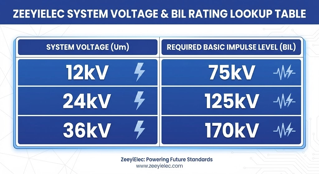
Figure 01:IEC 60137 coordination dictates that a bushing’s Basic Impulse Level (BIL) must align with the maximum system voltage to survive transient overvoltages.
Understanding Maximum System Voltage (Um)
Procurement and engineering teams must evaluate the network’s upper operational limits rather than its theoretical baseline.
A nominal 11 kV or 22 kV distribution network rarely operates exactly at those steady-state values. Grid fluctuations, load shedding, capacitive switching, and upstream tap changer operations mean an 11 kV line frequently runs closer to 12 kV. This requires engineers to specify bushings based on the Maximum System Voltage (Um). For example, a 33 kV system operating under standard tolerances requires a bushing rated for a Um of 36 kV. The fundamental rule in accessory selection is that the bushing’s rated voltage must be ≥ Um to prevent continuous partial discharge activity within the insulation matrix.
Basic Impulse Level (BIL) Coordination
While the rated voltage dictates continuous performance, the Basic Impulse Level (BIL)—also referred to as the lightning impulse withstand voltage—determines the bushing’s survivability during microsecond-duration transient overvoltages. Lightning strikes and switchgear operations generate high-frequency voltage spikes that travel along the lines and strike the transformer interface directly.
Under [NEED AUTHORITY LINK SOURCE: IEC Webstore page for IEC 60137 insulated bushings] guidelines, BIL ratings are strictly coordinated with maximum system voltages. For a standard 12kV distribution transformer, engineers typically specify a bushing with a 75kV or 95kV BIL, depending on the anticipated exposure to atmospheric overvoltages. Stepping up to a 24kV system demands a minimum 125kV BIL, while a 36kV network generally requires a 170kV BIL.
If the installation site is located at the end of a long overhead radial line without adequate surge arrester protection, conservative engineering practice dictates specifying the next highest BIL tier to add a critical margin of dielectric safety.
Expert Insight: Surge Arrester Proximity
BIL coordination assumes surge arresters are installed as close to the bushing terminal as practically possible. If arresters are mounted more than 3 meters away, the protective margin diminishes significantly due to inductive voltage drop in the connecting leads.
Expert Insight: Altitude Impact on BIL
Never accept a standard BIL rating for sites above 1000m without calculating the altitude correction factor. The air’s reduced dielectric strength means a bushing rated for 125kV BIL at sea level may only provide 110kV of protection at 2000m.
Expert Insight: Testing Documentation
Always demand routine test reports confirming the bushing passed dry power-frequency voltage withstand tests and partial discharge measurements prior to shipment.
Environmental Stress Factors and Site Conditions
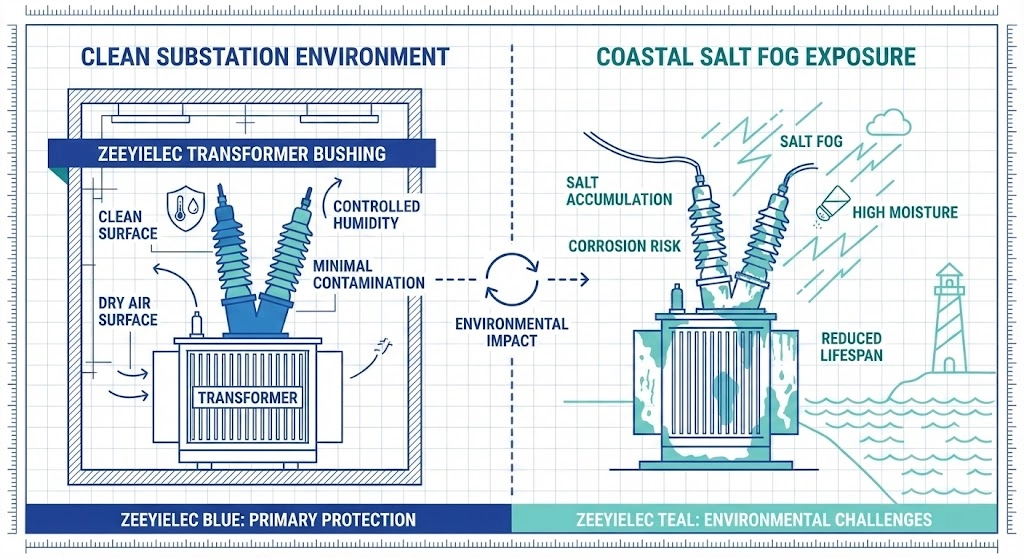
A bushing that performs flawlessly in a climate-controlled indoor switchgear room can fail within months when deployed to a coastal wind farm or a high-altitude mining site. The physical environment dictates the external insulation requirements just as stringently as the system’s electrical load. Failing to account for local atmospheric conditions inevitably leads to surface tracking, dry-band arcing, and eventual phase-to-ground flashovers.
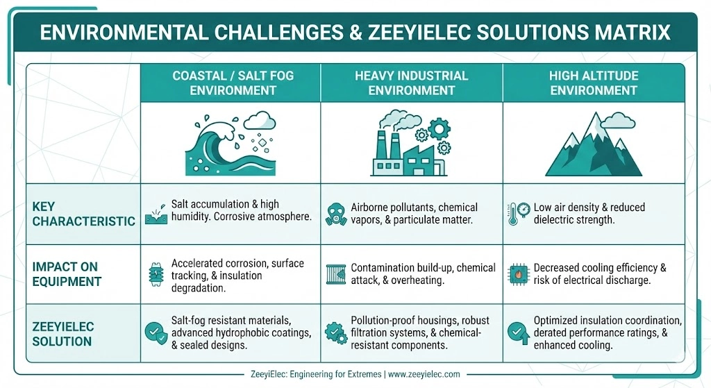
Figure-02:Site Pollution Severity (SPS) directly influences whether an extended creepage shed profile or standard insulation architecture is required.
Coastal and Salt Fog Environments
In marine environments, airborne salt spray continually settles onto the bushing sheds. During dry conditions, this salt remains relatively benign. However, field experience shows that when morning dew or light coastal fog moistens this layer, it creates a highly conductive brine film. If the Equivalent Salt Deposit Density (ESDD) is ≥ 0.2 mg/cm², leakage currents surge across the surface. Engineers must specify bushings with highly extended creepage profiles and aerodynamic shed designs that promote natural washing during heavy rain, preventing the buildup of these conductive films.
Heavy Industrial Pollution Zones
Installations near cement plants, steel mills, or heavy mining operations face a different threat profile. Unlike soluble coastal salts, industrial pollutants like coal dust, fly ash, and chemical particulate matter stick to the insulation and form a thick, stubborn crust. This Non-Soluble Deposit Density (NSDD) does not wash away easily. As leakage current flows through unevenly wetted pollution layers, the heat evaporates moisture in narrow bands. This leads to localized dry-band arcing—intense micro-sparks that physically burn and degrade the bushing’s exterior over time. In these environments, selecting materials with high tracking resistance is essential to preventing premature insulation breakdown.
High Altitude Derating (Above 1000m)
The dielectric strength of air is directly proportional to its density. As elevation increases, the air thins, reducing its ability to act as an effective insulator. For site installations ≥ 1000m above sea level, the external flashover voltage of a bushing decreases by approximately 1% for every 100 meters of additional elevation. If a 24kV distribution transformer is deployed at a 2500m mining site, the standard strike distances of a 24kV-rated bushing are no longer sufficient to prevent flashovers. To compensate for the thinner air, procurement teams must over-dimension the external insulation, frequently requiring the specification of a 36kV bushing on a 24kV system to maintain the required safety margins.
Material Selection: Porcelain vs. Epoxy Bushings
The physical shape of a bushing determines its creepage distance, but the material composition dictates its core dielectric strength, tracking resistance, and mechanical resilience. The industry standard historically relied entirely on wet-process porcelain, but cycloaliphatic epoxy resin has steadily gained ground over the last two decades. The selection between the two materials is not an absolute choice of one being superior, but rather matching the material properties to the installation environment and mechanical stresses.
When to Specify Porcelain (DIN/ANSI)
Porcelain remains the dominant material for standard utility distribution transformers, governed globally by [VERIFY STANDARD: IEC 60233 for hollow insulators] and ANSI/IEEE specifications. The fundamental advantage of porcelain is its almost absolute resistance to surface degradation. A high-quality aluminous porcelain bushing with a properly fired silica glaze forms an incredibly hard, hydrophilic surface.
When exposed to heavy UV radiation and extreme thermal cycling over 30 years, porcelain’s surface structure remains unchanged. It is practically impervious to tracking, even in heavy industrial zones, because the inorganic material simply cannot carbonize. For a standard 24kV, 250A distribution transformer installed in a typical outdoor substation, porcelain delivers reliable performance at an economical price point. However, its primary weaknesses are its brittle nature—making it susceptible to vandalism or impact damage during transit—and its significant weight, which increases mounting flange stress.
The Case for Cast Resin / Epoxy
Solid cast cycloaliphatic epoxy resin bushings offer a fundamentally different engineering profile. Epoxy is significantly lighter than porcelain and possesses exceptional tensile and impact strength, practically eliminating breakage during shipping or field installation. Because the central conductor is cast directly into the resin matrix, it also eliminates the internal air gap found in hollow porcelain designs, simplifying the internal field grading.
From a performance standpoint, modern hydrophobic cycloaliphatic epoxies actively repel water. Instead of forming a continuous conductive film during a coastal fog event, moisture beads up into isolated droplets, significantly reducing the leakage current. However, epoxy is an organic material. While highly UV-stabilized, prolonged exposure to severe dry-band arcing in highly polluted environments can eventually cause the surface to erode and track. Consequently, epoxy is often specified for indoor switchgear applications, pad-mounted low voltage bushings, and environments where mechanical vibration or seismic activity poses a threat to rigid porcelain structures.
Calculating Specific Creepage Distance
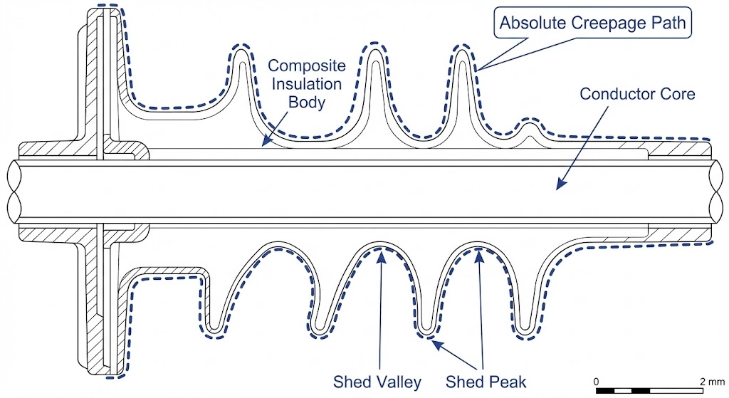
Figure-03:Creepage distance measures the shortest path along the external insulating surface from the energized high-voltage terminal to the grounded mounting flange.
Creepage distance is the shortest path along the exterior surface of an insulator between the high-voltage terminal and the grounded flange. Unlike the strike distance—which measures the straight-line clearance through the air—creepage dictates the bushing’s ability to resist surface tracking and leakage currents when environmental contaminants coat the insulation. Calculating the precise requirement prevents both over-engineering costs and catastrophic phase-to-ground flashovers.
IEC 60815 Pollution Severity Classes
The baseline for any creepage calculation relies on accurately classifying the installation environment. IEC 60815 establishes four primary Site Pollution Severity (SPS) classes, dictating the minimum specific creepage required per kilovolt of the maximum system voltage.
Light (Class I): Requires ≥ 16 mm/kV. Typical for clean inland areas or high-altitude sites with minimal industrial activity.
Medium (Class II): Requires ≥ 20 mm/kV. Used for non-polluting industrial areas or regions with occasional dry dust.
Heavy (Class III): Requires ≥ 25 mm/kV. Necessary for high-density industrial zones or areas located 10 to 20 kilometers from the coast.
Very Heavy (Class IV): Requires ≥ 31 mm/kV. Mandatory for coastal installations subjected to direct salt fog or severe industrial pollution environments.
The Creepage Formula in Practice
Once the pollution severity is established, determining the absolute creepage distance for the bushing is a straightforward calculation based on the system’s maximum operating voltage.
The governing equation is:Absolute Creepage Distance = Um × Specific Creepage Requirement
Consider a typical medium-voltage distribution network operating nominally at 20kV but with a maximum system voltage (Um) of 24kV. If the transformer is destined for a coastal desalination plant (Class IV pollution), the calculation requires the highest specific creepage multiplier:
Absolute Creepage = 24 kV × 31 mm/kV = 744 mm
In this scenario, specifying a standard indoor bushing with 400 mm of creepage would lead to rapid tracking and failure within the first year of operation. The procurement engineer must ensure the bushing manufacturer provides a component with an extended shed profile guaranteeing at least 744 mm of total surface distance.
Avoiding Field Failures: Installation and Sealing
A perfectly specified bushing rated for 36kV with 1200mm of creepage distance can fail catastrophically within weeks if the mechanical installation is flawed. The integrity of the environmental seal—the critical barrier preventing oil from escaping the tank and external moisture from penetrating the dielectric matrix—relies entirely on field execution. While engineers focus on electrical parameters during procurement, assembly technicians must master the mechanical interfaces.
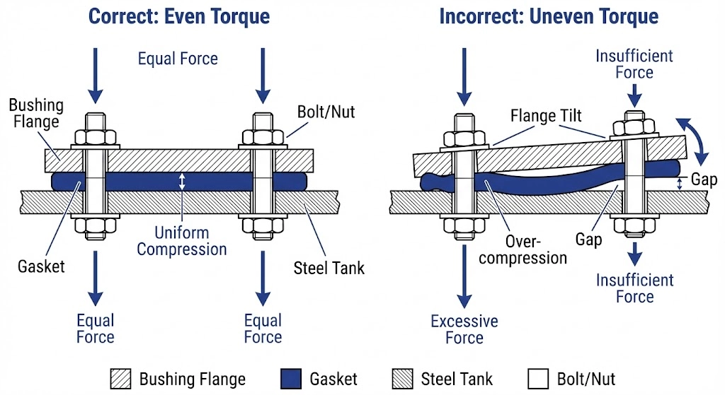
Figure 04:Uneven torque application causes asymmetric gasket compression, leading to immediate oil leaks or delayed seal degradation.
Torquing and Mechanical Stress
The primary interface between a medium voltage bushing and the transformer tank involves a mounting flange and a sealing gasket, typically composed of nitrile-butadiene rubber (NBR) or a similar oil-resistant elastomer. A common cause of early failure is uneven torquing of the flange bolts.
When technicians tighten bolts sequentially in a circle rather than using a star or cross-pattern sequence, the flange tilts. This uneven compression places excessive mechanical stress on one side of the porcelain body, which can cause micro-fractures in the silica glaze. Furthermore, it over-compresses the gasket on one side (often > 35% compression) while leaving the opposite side under-compressed (< 15% compression). Over-compressed NBR loses its elasticity and takes a permanent set, while under-compressed sections fail to seal against the internal oil pressure, which typically ranges from 0.3 to 0.7 bar (4.5 to 10 psi) in a distribution transformer.
Managing Oil Leaks at the Flange
When an unevenly seated gasket or a fractured porcelain body compromises the seal, the transformer slowly leaks its insulating dielectric fluid. This leads to a cascading failure mode. As the oil level drops below the internal energized terminal of the bushing, the high-voltage connection is exposed to the nitrogen blanket or ambient air inside the tank.
Because the dielectric strength of the insulating oil is substantially higher than the gas space above it, the exposed terminal experiences severe electrical stress. This initiates internal partial discharge, breaking down the remaining oil and generating combustible gases. If left unaddressed, the continuous arcing eventually causes a phase-to-ground fault within the tank. Properly sealing the interface with a calibrated torque wrench and following the manufacturer’s specified compression ratios is the most effective method for preventing these insidious environmental failures.
Expert Insight: Gasket Shelf Life
Nitrile rubber gaskets degrade over time, even in storage. Never use a gasket that has been sitting in an uncontrolled warehouse environment for more than three years, as ozone degradation leads to micro-cracking before installation even begins.
Expert Insight: Torque Wrench Calibration
Field crews must use recently calibrated torque wrenches. Applying an extra 10 Nm just to be safe on a porcelain flange is the leading cause of installation-induced micro-fractures.
Expert Insight: Visual Inspection
After 24 hours of resting post-installation, conduct a dry wipe test around the base of the flange. Even a microscopic weep of dielectric fluid indicates an imperfect seal that will worsen during thermal cycling.
Specifying and Sourcing MV Bushings for Your Project
Transitioning from theoretical sizing to actual procurement requires an airtight Request for Quotation (RFQ). Missing parameters routinely delay project schedules. To ensure your supplier can provide an accurate technical and commercial response, your specification must move beyond basic nameplate data.
At a minimum, your RFQ must define the maximum system voltage (Um), the required Basic Impulse Level (BIL), the continuous current rating (e.g., 250A or 630A), and the site pollution severity class. Additionally, stipulate the required interface standard—ANSI or DIN—as this dictates the bolt circle diameter and tank cutout dimensions, often requiring manufacturing tolerances as tight as ±2 mm.
For standard epoxy or porcelain configurations, transparent communication of your project timeline is critical. Typical manufacturing lead times range from 4 to 6 weeks depending on OEM customization requirements, raw material availability, and export testing protocols. Utilizing a structured <a href=””>Transformer Accessories RFQ Checklist (Engineer Edition)</a> prevents costly revision cycles and ensures all critical parameters are verified before the purchase order is issued.
Whether you are replacing an aging fleet of DIN porcelain units or engineering a new pad-mounted system requiring high-creepage epoxy profiles, Wenzhou Zeeyi Electric provides comprehensive technical selection support. Contact our engineering team with your project parameters and single-line diagrams to receive standard-compliant configuration data, export documentation, and accurate volume pricing to keep your production schedule on track.
Frequently Asked Questions
What is the difference between rated voltage and system voltage for a bushing?
Rated equipment voltage represents the maximum continuous voltage the bushing can safely withstand mechanically and electrically, while system voltage is the nominal operating grid voltage. Always select a bushing where the rated voltage is equal to or higher than the highest expected system voltage to prevent premature dielectric breakdown during normal load fluctuations.
How do you adjust bushing selection for altitudes above 1000 meters?
For installations above 1000m, dielectric strength decreases by approximately 1% per 100 meters of elevation, requiring a higher BIL rating or an over-dimensioned voltage class. If your 12kV system sits at 2500m, you must specify a 24kV bushing or request altitude-corrected strike distances to prevent flashovers in the thinner air.
Can I replace a porcelain bushing with an epoxy bushing of the same rating?
While electrically compatible, replacing porcelain with epoxy requires verifying the mounting flange dimensions, bolt circle diameter, and internal clearance distances within the transformer tank. Epoxy offers superior impact resistance, but you must ensure the existing transformer cutout matches the new bushing’s profile to maintain a proper hermetic oil seal.
What creepage distance is required for a coastal 24kV transformer installation?
Coastal environments are classified as heavy or very heavy pollution zones, requiring a minimum specific creepage distance of ≥ 25 mm/kV. For a 24kV system in a marine environment, specify a bushing with an absolute creepage distance between 600 mm and 744 mm to prevent salt-induced surface tracking.
How do you specify the current rating for an MV distribution transformer bushing?
The bushing current rating should exceed the transformer’s maximum load current by a safety margin of ≥ 20% to accommodate continuous overloads and harmonic heating. For a 1000kVA 11kV transformer with a 52A nominal primary current, a standard 250A MV bushing is typically specified to ensure long-term thermal stability.
What causes dry-band arcing on a medium voltage bushing?
Dry-band arcing occurs when airborne pollutants settle on the bushing and become moistened by fog or dew, creating a conductive layer for leakage currents. As the current flows, the resulting heat evaporates the moisture in narrow strips, forcing intense electrical sparks to jump across the dry gaps, which slowly degrades the insulation surface.
yoyo shi
Yoyo Shi writes for ZeeyiElec, focusing on medium-voltage accessories, transformer components, and cable accessory solutions. Her articles cover product applications, technical basics, and sourcing insights for global electrical industry buyers.