A missing data point in your Request for Quotation does not simply slow down procurement. It triggers a cascade: suppliers send clarification emails, your engineering team hunts for cable datasheets, and the quotation deadline slips. Multiply this across six or eight line items on a substation project, and what should have been a two-week RFQ cycle stretches into six weeks.
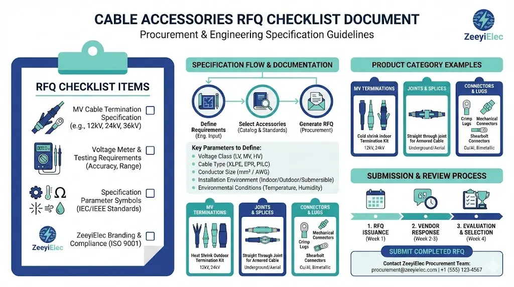
This cable accessories RFQ checklist provides a systematic framework for specifying terminations, joints, and separable connectors. Whether you are procuring cold shrink cable accessories or heat shrink cable accessories for medium-voltage projects, the following sections cover every parameter your supplier needs to quote accurately and deliver compatible products.
Why Cable Accessory Projects Fail Without a Complete RFQ
Field experience points to a consistent set of failure modes across MV and HV cable accessory procurement worldwide.
The cable datasheet gap. An RFQ specifies “300 mm² XLPE cable, 24 kV” but omits the cable manufacturer, insulation outer diameter, and screen type. The supplier cannot determine whether the cable uses copper tape screen (requiring one earthing kit design) or wire screen (requiring another). The quotation stalls.
The altitude oversight. A project site sits at 2,400 meters elevation in the Andes or Ethiopian highlands. Standard creepage distances sized for sea-level installations fall short at altitude. Without this data in the RFQ, the supplier quotes standard accessories—and engineering review catches the error weeks later.
The “or equivalent” trap. RFQ language permits “Brand X or equivalent” without defining equivalence criteria. When a lower-cost supplier offers an alternative product, the evaluation committee lacks criteria to assess whether the substitution meets requirements. Disputes follow.
These are not hypothetical scenarios. A 2023 distribution network upgrade in Southeast Asia required 48 sets of 24 kV outdoor terminations. The initial RFQ omitted cable screen cross-sectional area. The first supplier shipment included earthing kits rated for 16 mm² wire screen; the actual cables used 25 mm² copper tape screen. The kits could not accommodate the larger screen, adding three weeks to the installation schedule.
System Voltage and Electrical Parameters Checklist
When procurement teams issue RFQs for cable accessories, electrical specifications form the non-negotiable baseline separating qualified products from potential failure points.
The voltage rating specification requires particular precision. For medium-voltage cable accessories serving 6–36 kV networks, IEC 60502-4 mandates that accessories demonstrate withstand capability at U0/U levels appropriate to the system earthing configuration. A 12/20 kV rated accessory must pass AC withstand testing at 42 kV (2.1 × U0) and lightning impulse testing at 125 kV BIL minimum.
Your RFQ must capture these electrical parameters explicitly:
Parameter
Required Data
Example Value
System Voltage (Um)
Maximum operating voltage
24 kV
Basic Impulse Level
Lightning impulse withstand
125 kV
AC Withstand
Power frequency test voltage
50 kV
Short-Circuit Rating
Fault current and duration
25 kA / 1s
Earthing Configuration
System grounding method
Solidly grounded
Partial discharge performance represents a critical quality indicator. Per IEC 60502-4, accessories for distribution cables rated 6–36 kV must demonstrate PD levels below 10 pC at 1.73 × U₀ during type testing. Stress control methodology—geometric stress cones, high-permittivity grading materials, or refractive field control—deserves explicit specification. EPDM rubber cold shrink products typically incorporate integrated stress control with relative permittivity (εᵣ) values between 20 and 30 at the stress relief zone.
Figure 1. Essential electrical parameters for cable accessory specification — system voltage (Um), basic impulse level (BIL), AC withstand, short-circuit rating, and earthing configuration determine accessory compatibility and safety margins.
[Expert Insight: Voltage Class Selection]
Specify maximum system voltage (Um), not nominal voltage—a 20 kV system typically requires 24 kV class accessories
BIL ratings commonly range from 95 kV (15 kV class) to 150 kV (25 kV class) for distribution applications
Request certificates showing test voltage specific to your earthing configuration (solidly grounded vs. resistance grounded)
Cable Construction Data Your Supplier Needs
Cable accessories must interface precisely with the cable construction they serve. The dimensional and material parameters governing compatibility cannot be assumed or generalized.
Conductor specifications determine compression lug sizing and contact resistance. Document conductor material (copper or aluminum), cross-sectional area (typically 35–1000 mm² for MV applications), and stranding type (solid, stranded, or compact stranded). A 300 mm² compact stranded conductor has a smaller diameter than standard stranding—specifying only cross-sectional area leads to oversized lugs and poor contact.
Insulation and jacket details affect stress control design and sealing interfaces. Specify insulation type (XLPE or EPR), nominal thickness, and outer diameter over insulation. Include outer jacket material (PVC, PE, or LSZH) and overall cable diameter with tolerances—typically ±1.5 mm for MV cables.
Screen configuration causes more RFQ failures than any other parameter. Copper tape screen, wire screen, and lead sheath constructions require completely different earthing kits and stripping procedures. Document screen type and cross-sectional area explicitly. A 16 mm² earthing kit will not accommodate 25 mm² screen conductors.
Parameter
Required Data
Impact on Accessory Selection
Conductor Material
Cu / Al
Lug material compatibility
Conductor Size
mm² with tolerance
Compression barrel sizing
Insulation Type
XLPE / EPR
Stress control geometry
Insulation OD
mm ± tolerance
Tube expansion range
Screen Type
Tape / Wire / Lead
Earthing kit design
Overall Cable OD
mm ± tolerance
Accessory sizing
Per IEC 60502-4 , accessories must accommodate specified cable construction ranges without compromising sealing integrity or electrical performance.
Installation Environment Specifications
Site conditions determine whether standard accessories meet requirements or require enhanced specifications. Indoor, outdoor, underground, and subsea installations each demand different material properties and ratings.
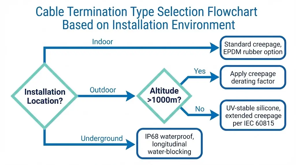
Location classification drives fundamental design requirements. Indoor terminations use standard creepage distances and may employ EPDM rubber without UV stabilization. Outdoor terminations require UV-stable silicone rubber sheds meeting IEC 62217 for polymeric insulators, with extended creepage appropriate to pollution severity. Underground joints must provide IP68-rated waterproofing and longitudinal water-blocking.
Altitude and ambient conditions affect dielectric performance directly. At elevations above 1,000 meters, reduced air density decreases external insulation strength. [VERIFY STANDARD: IEC 60071-2 altitude correction factors] Standard creepage distances require derating—typically 1% per 100 meters above 1,000 m. An RFQ for a 2,500 m elevation site must specify this requirement explicitly.
Space and access constraints influence accessory technology selection. Cold shrink accessories require no heat source and suit confined cable pits where torch work is impractical. Heat shrink accessories offer cost advantages but need adequate clearance for uniform heating. Document pit dimensions, minimum bending radius, and whether open-flame tools are permitted.
Figure 2. Termination type selection flowchart — installation environment classification determines material requirements, creepage distances, and ingress protection ratings for cable accessories.
☐ Ambient temperature range: _______ °C to _______ °C
☐ Pollution severity: Light / Medium / Heavy / Very Heavy (per IEC 60815)
☐ Space constraints: Pit dimensions _______ × _______ mm
Accessory Type and Quantity Schedule Template
Accurate accessory scheduling prevents both shortages and excess inventory. The schedule must capture accessory type, voltage class, conductor range, and quantity with appropriate spares.
Termination types include indoor (porcelain or polymeric), outdoor (standard or extended creepage), and GIS plug-in configurations for gas-insulated switchgear interfaces. Separable connectors—elbow connectors and T-body designs—enable modular connections at padmount transformers and ring main units.
Joint types serve different applications. Straight joints connect identical cable constructions. Transition joints bridge different insulation systems (XLPE to paper) or conductor materials (copper to aluminum). Branch joints and Y-joints distribute circuits where required.
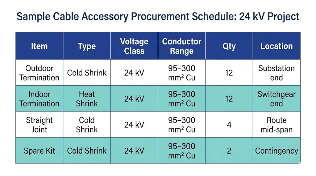
Quantity calculation follows a straightforward formula: circuits × phases × termination points, plus joints for mid-span connections or cable route extensions. Industry practice recommends 5–10% spare kits for projects exceeding 20 accessory sets, covering installation damage or specification changes during construction.
Figure 3. Sample accessory schedule for 24 kV distribution project — quantity calculation includes terminations at both ends, mid-span joints, and 5–10% spare kits for installation contingency.
Item
Type
Voltage Class
Conductor Range
Qty
Location
Outdoor Termination
Cold Shrink
24 kV
95–300 mm² Cu
12
Substation end
Indoor Termination
Heat Shrink
24 kV
95–300 mm² Cu
12
Switchgear end
Straight Joint
Cold Shrink
24 kV
95–300 mm² Cu
4
Route mid-span
Spare Termination Kit
Cold Shrink
24 kV
95–300 mm² Cu
2
Contingency
[Expert Insight: Spare Kit Strategy]
Standard recommendation: 5–10% spares for projects with 20+ accessory sets
Critical infrastructure projects may warrant 15% spares due to higher consequence of delay
Store spares in climate-controlled conditions; EPDM rubber components degrade in UV exposure
Document spare allocation by circuit to simplify future maintenance procurement
Documentation and Type Test Requirements
Technical documentation validates that cable accessories meet performance requirements before installation. Your RFQ must specify which documents suppliers must provide and which standards govern acceptance.
Type test reports demonstrate that the accessory design passed qualification testing. For terminations, IEEE 48 governs testing in North America while IEC 60502-4 applies internationally for MV accessories rated 6–36 kV. For joints, IEEE 404 and IEC 60502-4 establish testing protocols. Request test reports matching your specific voltage class and cable construction—a 15 kV type test does not qualify a 25 kV application.
Routine test certificates verify that production units meet quality standards. Typical routine tests include power frequency withstand at 3.5 × U₀ for 5 minutes and partial discharge measurement with acceptance below 5 pC at 1.5 × U₀. Each production lot should carry traceable documentation.
Quality system certifications provide supply chain confidence. ISO 9001 certification demonstrates systematic quality management. Material certifications trace EPDM and silicone compounds to qualified sources.
Installation documentation affects both execution and warranty. Request installation manuals in your project language, with clear dimensional specifications and step-by-step procedures. Some manufacturers require installer training certification for warranty validity—clarify this requirement before order placement.
Document
Required
Governing Standard
Type Test Report
✓
IEEE 48 / IEC 60502-4
Routine Test Certificate
✓
Per production lot
ISO 9001 Certificate
✓
Current validity
Material Certificates
Recommended
Compound traceability
Installation Manual
✓
Project language
RFQ Mistakes That Cause Project Delays
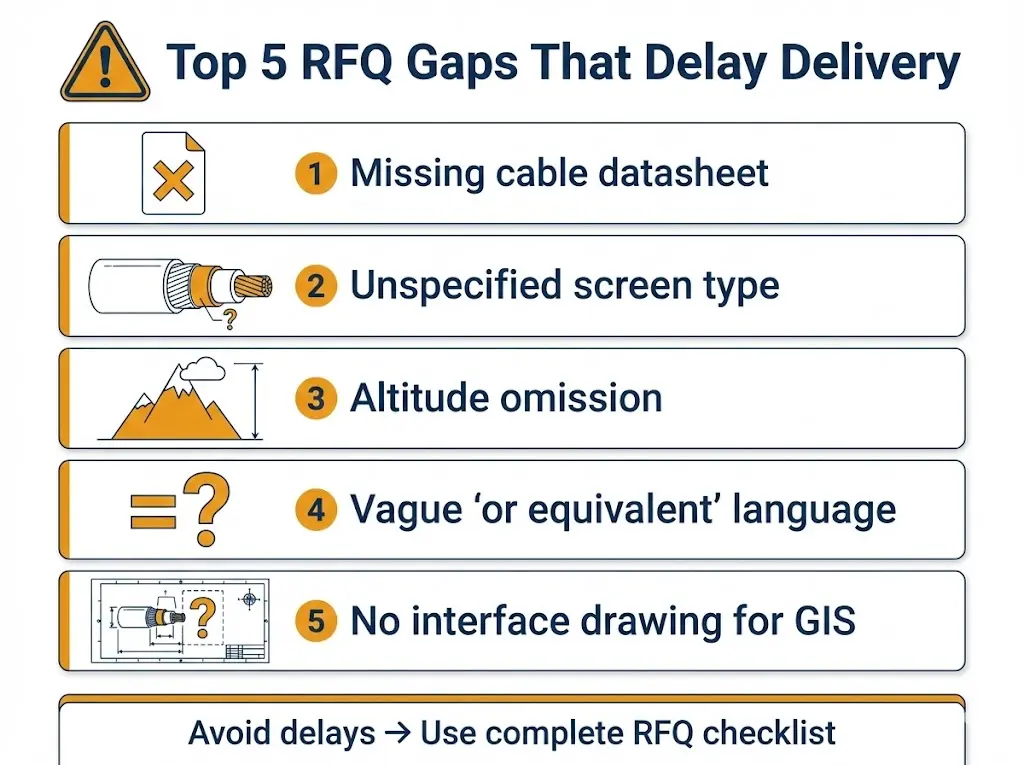
Certain RFQ gaps appear repeatedly across projects, each capable of adding weeks to procurement cycles. Recognizing these patterns helps procurement teams avoid preventable delays.
Missing cable datasheet forces suppliers to estimate dimensions. Kit sizing errors result, discovered only when installers attempt to fit accessories onto cables that fall outside the specified range. Always attach the cable manufacturer’s datasheet to your RFQ.
Unspecified screen type causes earthing accessory mismatches. Copper tape screen, wire screen, and concentric neutral constructions require different termination kits. The 2023 Southeast Asia project failure—earthing kits incompatible with actual screen construction—exemplifies this risk.
Altitude omission leads to underspecified creepage distances. Sites above 1,000 m require altitude-corrected accessories or explicit creepage specification. Standard sea-level designs may experience tracking or flashover at elevation.
Vague equivalence language creates evaluation disputes. “Or equivalent” without defined acceptance criteria leaves evaluation committees without objective comparison basis. Specify which parameters must match (voltage class, type test standard, material) and which may vary.
No interface drawing for GIS or switchgear terminations prevents dimensional verification. Plug-in terminations must match specific switchgear interface geometries—request equipment drawings and include them in your RFQ package.
Figure 4. Common RFQ gaps causing procurement delays — each omission triggers clarification cycles that can extend quotation timelines by weeks and compromise accessory-cable compatibility.
Get RFQ Support from ZeeyiElec’s Engineering Team
Preparing comprehensive cable accessory specifications requires both technical knowledge and practical procurement experience. ZeeyiElec’s engineering team supports buyers throughout the RFQ development process.
Our cable accessories portfolio includes cold shrink and heat shrink terminations and joints for medium-voltage systems rated 6–36 kV. Type test documentation per IEC 60502-4 is available upon request for all standard voltage classes and conductor ranges.
Contact our technical team for:
RFQ specification review and completeness verification
Accessory selection recommendations based on cable construction data
Type test report packages for tender documentation
Installation training coordination for project teams
Ready to start your cable accessory RFQ? Submit your project requirements through our inquiry form, email, or WhatsApp for engineering consultation within 24 hours.
Frequently Asked Questions
Q: What minimum information must a cable accessories RFQ contain?
A: At minimum, specify system voltage (Um with BIL), cable conductor size and material, insulation type and outer diameter, screen configuration with cross-sectional area, installation environment classification, and required quantity with delivery timeline.
Q: How do I select the correct voltage class for cable terminations?
A: Use maximum system voltage (Um) rather than nominal voltage for selection—a 20 kV nominal system typically operates at up to 24 kV Um, requiring 24 kV class accessories to maintain adequate margins during voltage transients and testing.
Q: Why does cable screen type cause so many RFQ problems?
A: Copper tape, wire screen, and lead sheath constructions require physically different earthing kits and preparation procedures; accessories designed for one screen type cannot properly terminate another, leading to installation failures or inadequate fault current paths.
Q: How many spare cable accessory kits should I specify?
A: Industry practice recommends 5–10% spares for projects exceeding 20 accessory sets, increasing to 15% for critical infrastructure where extended outage consequences justify additional inventory investment.
Q: What type test standards apply to MV cable accessories internationally?
A: IEC 60502-4 covers extruded cable accessories rated 6–36 kV internationally, while IEEE 48 (terminations) and IEEE 404 (joints) govern North American applications; request test reports matching your specific voltage class and cable type.
Q: Should I specify cold shrink or heat shrink technology in my RFQ?
A: Base selection on installation constraints—cold shrink requires no tools or heat source and suits confined spaces with fire restrictions, while heat shrink offers lower material cost for large quantities where adequate torch clearance and ventilation exist.
Q: What documentation should I require for warranty validity?
A: Request type test reports, routine test certificates for the production lot, and written confirmation of warranty terms including whether installer training certification is required—some manufacturers void warranties when untrained personnel perform installation.
yoyo shi
Yoyo Shi writes for ZeeyiElec, focusing on medium-voltage accessories, transformer components, and cable accessory solutions. Her articles cover product applications, technical basics, and sourcing insights for global electrical industry buyers.