In distribution transformer engineering, the distinction between the bushing well and the bushing body (often referred to as the bushing insert or integral bushing) is fundamental to both dielectric safety and system modularity. Together, they form a separable insulated connector system that allows for dead-front operation in oil-filled equipment. This modular approach separates the permanent structural housing from the replaceable electrical interface, providing a flexible framework for utility and industrial distribution networks.
Defining the Interface: The Structural Anatomy of Well-Mounted Bushings
The boundary between the structural housing and the electrical insert is a critical junction in pad-mounted or substation transformers.
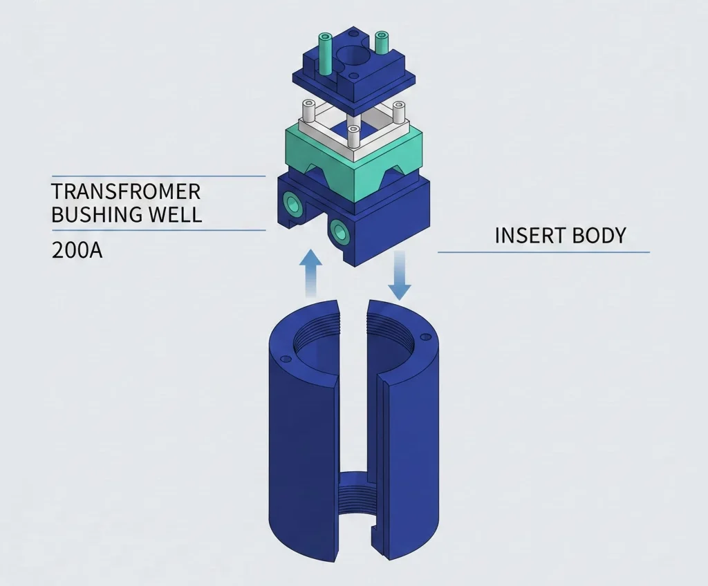
The Bushing Well: The Female Receptacle
The bushing well serves as the primary structural housing, permanently mounted to the transformer tank wall. Manufactured primarily from high-grade epoxy resin, it provides a universal interface for various types of inserts. Its core role is to maintain a hermetic seal against the transformer oil while providing a cavity designed for an interference fit with the bushing body. In standard transformer accessories configurations, the well includes a copper or brass stud at the base that connects directly to the internal leads.
The Bushing Body: The Male Insert and Conductor Path
The bushing body—specifically the bushing well insert—is the component that interfaces with the cable connector. While the well is a passive receptacle, the body is an active dielectric component. It contains the primary conductor and, in load-break variants, the arc-quenching material required to interrupt current. The body is threaded into the well, and its outer surface must perfectly mate with the well’s internal surface to eliminate air pockets.
Mechanical Sealing: Gaskets and Locking Mechanisms
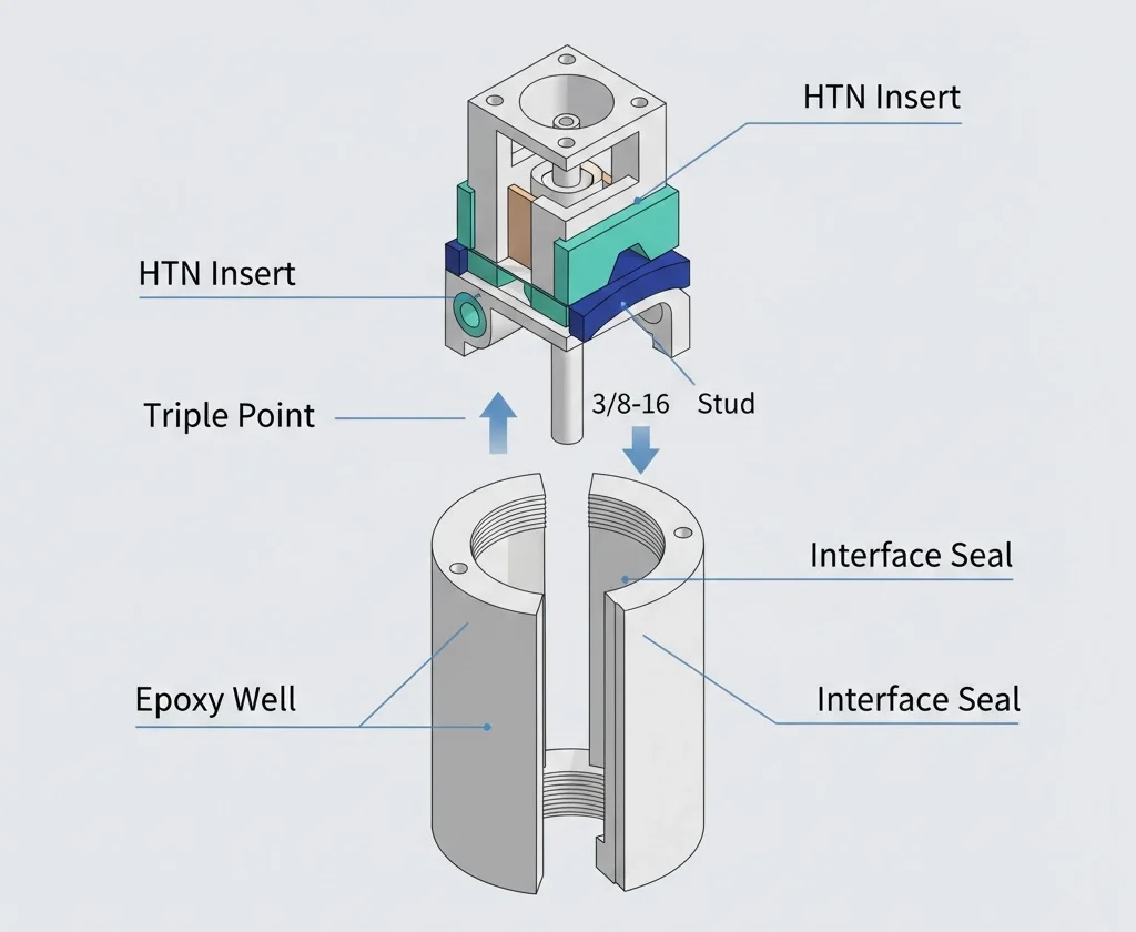
The boundary between these two components is where insulation integrity is most tested. To ensure longevity, the well is bolted to the tank using a mounting flange and a high-performance gasket, typically made of Buna-N or Fluorocarbon. The body utilizes a 3/8″-16 UNC threaded connection to secure itself into the base of the well. This mechanical coupling must withstand the physical forces of cable manipulation and thermal cycling without compromising the dielectric seal.
Dielectric stress management at the well-body interface is governed by the permittivity (ε) of the insulation materials. The breakdown strength must exceed the maximum voltage stress (Emax) at the triple point where the conductor, solid insulation, and shielding meet. For 200A interfaces, this requires a minimum dielectric withstand of 34kV AC for 1 minute as per the [NEED AUTHORITY LINK SOURCE] (suggested anchor: IEEE 386 standard for separable connectors).
The dielectric integrity of the assembly relies on the voltage gradient being managed across the interface. Standard 15kV class wells are designed for a Basic Impulse Level (BIL) of 95kV, while 25kV classes must withstand 125kV. The physical clearance (d) and creepage path (Lc) are calculated to prevent surface flashover under maximum operating temperatures (Tmax ≤ 105°C).
Figure-01:Detailed cross-sectional view illustrating the interference fit between the cast-epoxy well and nylon body, specifically marking the dielectric triple point and the 3/8″-16 UNC threaded mechanical seal.
Electrical Performance Boundaries: Ratings and Limits
The electrical performance of the assembly is governed by strict boundary conditions that ensure the system operates safely under continuous load and transient fault conditions. These limits are primarily defined by IEEE 386, which standardizes the interface dimensions for medium voltage bushings.
Voltage Class Limits for Standard Wells
Bushing wells are categorized into specific voltage classes: 15 kV, 25 kV, and 35 kV. The boundary of each class is defined by the maximum phase-to-ground voltage. For instance, a 15 kV class well is designed for systems where the phase-to-ground voltage is approximately 8.3 kV. Exceeding these boundaries leads to increased partial discharge activity, which can rapidly degrade materials through carbon tracking.
Continuous Current vs. Overload Capacity
Standard bushing wells are rated for 200 A continuous current. In contrast, 600 A systems often utilize integral bushings to manage higher thermal loads and magnetic forces. Under emergency conditions, these components must handle specific overload cycles (e.g., 300 A for limited durations) without exceeding the thermal limits of the transformer oil.
The BIL requirements are strictly mapped to system voltage. For a 15 kV system, the standard BIL is 95 kV. As the voltage increases to 25 kV and 35 kV, the BIL boundaries shift to 125 kV and 150 kV, respectively. The dielectric withstand is verified through a 60 Hz power frequency test and a negative/positive impulse test sequence (1.2/50 μs wave). IEEE 386 remains the definitive [NEED AUTHORITY LINK SOURCE] (suggested anchor: authority for separable connector ratings) in this domain.
Creepage and Clearance Distance Requirements
Minimum creepage distances (Lc) are calculated based on site pollution levels. In standard environments, a creepage of ≥ 280 mm is typical for 15 kV applications. The boundary between the grounded tank and energized terminal must maintain a clearance (S) accounting for peak voltage (Vpeak) and atmospheric pressure, ensuring dielectric strength is maintained up to 105°C.
[Expert Insight: Dielectric Integrity]
Triple Point Stress: The junction where the well, body, and conductor meet is the highest stress point; ensure the body is fully seated to avoid air ionization.
PD Sensitivity: Partial discharge levels should be monitored during factory acceptance tests (FAT); levels > 5pC at 1.5x operating voltage indicate interface air gaps.
Material Compatibility: Ensure cleaning solvents do not degrade the silicone interface of the bushing body.
Comparison Matrix: Bushing Well vs. Bushing Body
Understanding the divergent roles of these components is critical for managing spare parts inventories.
Functional Priority: Containment vs. Connection
The bushing well is a containment vessel and structural anchor. Its boundary is defined by the transformer tank; it must withstand internal oil pressure and mechanical stress. Conversely, the bushing well insert is the active electrical connection point that manages the interface with cable elbows and handles switching arc energy.
Replacement Frequency and Serviceability
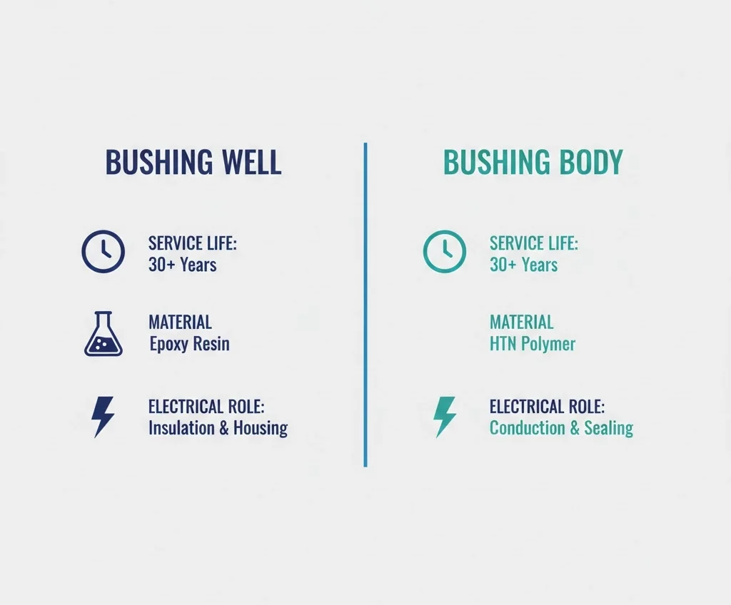
The bushing well is designed for a 25–40 year life. The bushing body is a serviceable item. It can be unthreaded and replaced if contacts become worn or if the interface is damaged by improper cable handling. In most field scenarios, a damaged 200A interface is corrected by swapping the body, leaving the well intact.
Material Differences: Epoxy Resin vs. High-Temperature Nylon (HTN)
Bushing wells are cast from epoxy resin for long-term oil resistance. Bushing bodies, particularly inserts, often use High-Temperature Nylon (HTN) for superior thermal resilience during high-current operations.
Comparison Table: Well vs. Body (Insert)
Feature
Bushing Well
Bushing Body (Insert)
Standard Current
200A (Universal Interface)
200A (Load-break / Dead-break)
Voltage Classes
15kV, 25kV, 35kV
15kV, 25kV, 35kV
Common Material
Cast Epoxy Resin
HTN or Filled Epoxy
Serviceability
Fixed (Non-serviceable)
Removable / Replaceable
Figure-02:This technical infographic compares the structural role of the permanent epoxy well against the functional connection role of the HTN insert body, focusing on material stability and replacement frequency.
Selection Framework for Transformer Engineers
Engineers must evaluate components against project-specific variables such as current load and the type of cable accessories being deployed.
Matching the Well to the Transformer Tank Wall
Most standard 200A wells require a mounting hole of approximately 2.125 inches (54 mm). Installation torque for mounting bolts must be precisely controlled—typically 20 N·m (approx. 15 ft-lbs)—to ensure a leak-free seal without cracking the epoxy flange.
Interface Compatibility: Dead-break vs. Load-break Inserts
The choice of “body” depends on operational requirements. Load-break inserts are essential for switching under load using a hot-stick, while dead-break inserts are cost-effective for static industrial connections where circuits are de-energized before disconnection.
Field Assembly and Installation Realities
The transition from high-precision components to a functional interface occurs during field assembly. The most frequent cause of premature failure is the entrapment of air or contaminants at the dielectric interface.
Torque Management for Bushing Wells and Inserts
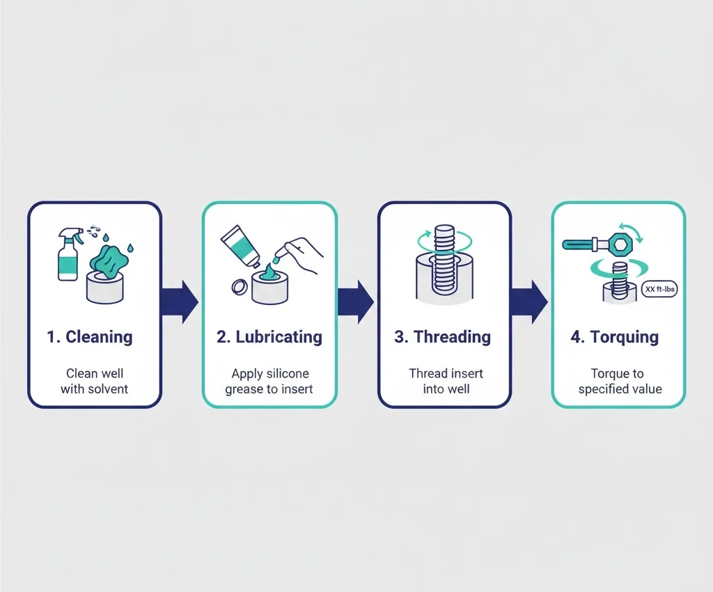
For standard 3/8″-16 UNC threaded interfaces, the assembly torque (Ta) should typically range between 50 and 60 ft-lbs (68–81 N·m). Insufficient torque leads to high contact resistance (Rc > 100 μΩ), causing localized resistive heating.
Lubrication Protocols for Dielectric Interfaces
Dielectric interfaces require a thin layer of silicone grease to displace air. Because air has a lower dielectric constant (ε<sub>r</sub> ≈ 1) than epoxy (ε<sub>r</sub> ≈ 4), stress in air gaps is magnified, triggering partial discharge and eventual carbon tracking.
Figure-03:Field assembly validation sequence emphasizing the critical nature of silicone lubrication to displace air at the interface and the application of 55 ft-lbs torque to ensure low contact resistance.
[Expert Insight: Field Reliability]
Thread Protection: hand-start the 3/8″ stud to prevent cross-threading; if resistance is felt before 3 turns, stop and re-align.
Piston Effect: Insert the body with a slow, clockwise twisting motion to allow trapped air to vent through the threads.
Gasket Seat: Check the tank surface for paint runs or burrs that could prevent the well gasket from seating flat.
Identifying and Preventing Interface Failures
Failures in this region result from long-term degradation triggered by initial assembly errors. By understanding root causes, teams can implement predictive strategies to prevent common field failure modes.
Partial Discharge and Thermal Degradation
PD occurs when electric field stress exceeds the breakdown strength of trapped air. Over time, these discharges erode the surfaces, creating “trees.” Mechanical failures often stem from the 3/8″-16 UNC threaded coupling; cross-threading results in a high-resistance junction that generates significant heat.
Failure Mode Analysis Chart
Dielectric Tracking
Symptom: Audible buzzing or visible carbon tracks upon disassembly.
Root Cause: Inadequate lubrication or presence of dust/moisture.
Thermal Hotspot
Symptom: Discoloration of the bushing body or melting of the cable elbow.
Root Cause: Loose threaded connection or oxidized contacts.
Hermetic Seal Breach
Symptom: Oil weeping around the well flange.
Root Cause: Gasket degradation or over-torqued mounting bolts.
Streamlining Your Accessory Procurement
Managing procurement requires treating these components as a synchronized system. Using a unified transformer accessories RFQ checklist ensures that parameters like BIL (95kV vs. 125kV) are communicated clearly.
Ready to optimize your transformer protection and connection systems? ZeeyiElec provides engineered 200A bushing wells and high-performance inserts tailored for 15kV to 35kV distribution networks. Contact our technical team today for model matching support or to receive a comprehensive quotation for your next project.
Frequently Asked Questions
Can I install a different brand of bushing body into a ZeeyiElec bushing well?
Standardized 200A interfaces follow the IEEE 386 universal dimensions, allowing for intermateability across brands as long as the voltage class and threaded stud specifications match.
Why is the bushing well usually epoxy while the insert is sometimes nylon?
Epoxy provides high structural rigidity and oil resistance for a permanent tank-mounted housing, while high-temperature nylon offers the thermal stability needed for the active conductor path.
What is the primary cause of tracking between the well and the body?
Carbon tracking is almost always caused by trapped air pockets or surface contaminants that trigger partial discharge at the dielectric interface during assembly.
How do I determine if I need a 200A well or a 600A integral bushing?
A 200A well system is designed for modular, load-break operations in distribution networks, while 600A integral bushings are required for higher continuous current and dead-break connections.
Does a bushing well require a specific gasket for oil-filled transformers?
Yes, high-grade Buna-N or Fluorocarbon O-rings are necessary to maintain a hermetic seal against hot transformer oil at temperatures ranging from -40°C to 120°C.
How often should the interface between the well and body be inspected?
Routine infrared thermography every 12 to 24 months is recommended to identify thermal hotspots indicating poor electrical contact at the base stud.
Can a bushing well be repaired if the mounting threads are stripped?
Stripped threads on the primary mounting or contact stud typically require a full replacement of the well to maintain the mechanical and electrical integrity of the pressure joint.
yoyo shi
Yoyo Shi writes for ZeeyiElec, focusing on medium-voltage accessories, transformer components, and cable accessory solutions. Her articles cover product applications, technical basics, and sourcing insights for global electrical industry buyers.