When a 200A loadbreak interface fails in the field, the root cause is rarely an instantaneous manufacturing defect. These components operate as the critical demarcation point between a distribution transformer’s internal environment and the external underground cable network. To successfully diagnose why fail under continuous operating conditions, field personnel must first understand the intense multi-variable stresses acting upon this specific interface.
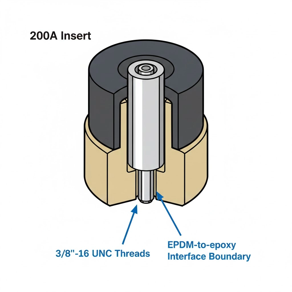
The anatomy of an insert failure is fundamentally tied to the physics of its construction. The assembly relies on a high-stress dielectric boundary formed by the interference fit between the insert’s molded EPDM (Ethylene Propylene Diene Monomer) rubber and the rigid epoxy of the transformer well. Additionally, the internal copper stud provides the sole mechanical and electrical connection to the transformer winding. When this structural equilibrium is disturbed, failure pathways emerge across three distinct domains:
Mechanical Failures: These originate during installation or switching operations. Cross-threading the copper stud, applying excessive torque that fractures the epoxy well, or hydraulic lock from improper lubrication directly compromises the interface’s physical geometry.
Thermal Degradation: Mechanical misalignment or insufficient seating torque prevents full metal-to-metal contact at the base. This elevated contact resistance generates localized heat that degrades the surrounding EPDM rubber.
Dielectric Breakdown: If the interference fit fails to expel all air and moisture, the resulting voids ionize under high electrical stress, leading to corona, carbon tracking, and eventual phase-to-ground faults.
At 15kV to 35kV voltage classes, the margin for error is virtually zero. When mechanical integrity is lost—whether due to a microscopic air void ≥ 0.1 mm or compromised copper threads—it inevitably triggers a cascade of thermal and dielectric failure mechanisms. Poor contact introduces elevated I²R heating, which continuously raises the localized ΔT. Simultaneously, any trapped air in the high-stress interface ionizes, ultimately breaking down the dielectric boundary of these critical transformer accessories.
Figure 1: The mechanical and electrical integrity of the insert relies on the critical metal-to-metal contact at the base and the interference fit along the cone.
[Expert Insight: Realities of Interface Diagnostics]
Over 75% of insert failures investigated in the field show root causes stemming from mechanical installation errors, rather than material defects.
Dielectric degradation is silent; an interface can operate for 12 to 18 months with active partial discharge before escalating to a detectable phase-to-ground fault.
Because the insert and the permanent transformer well share a direct threaded connection, diagnosing the insert requires simultaneous inspection of the well’s epoxy surface and internal copper threads.
Thermal Degradation: Diagnosing High Contact Resistance
A significant portion of bushing well insert failures presents as thermal degradation. When analyzing an overheated interface, the root cause is almost exclusively elevated contact resistance between the insert’s copper stud and the internal threading of the transformer well. Identifying these symptoms before they escalate to a total fault is critical for network reliability.
The Physics of Contact Resistance
In a correctly torqued 200A interface, the mechanical compression ensures optimal metal-to-metal contact, keeping internal resistance below the 50 μΩ to 100 μΩ baseline. However, if the insert is under-torqued during installation, or if the threads are contaminated with debris or old thread-locker, the effective contact area shrinks dramatically.
This reduced contact area directly increases the resistance (R). Because heat generation follows the equation P = I²R, even moderate load currents on an under-torqued interface will cause a disproportionate temperature rise (ΔT). The heat originates at the stud and conducts outward into the EPDM rubber. EPDM has excellent dielectric properties but begins to degrade physically when continuously subjected to temperatures ≥ 130°C. The thermal expansion of the overheated copper further distorts the rubber, permanently compromising the interference fit.
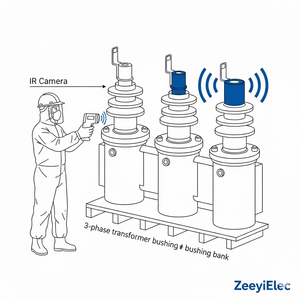
Visual and Thermographic Signatures of Heating
Field crews typically diagnose thermal issues through two distinct signatures. During energized inspections, infrared (IR) thermography is the primary tool. A healthy insert should operate within a few degrees of the ambient transformer oil temperature. A localized hot spot at the base of the insert—often showing a ΔT of 20°C or more compared to adjacent phases—is a definitive indicator of high contact resistance [NEED AUTHORITY LINK SOURCE: IEEE Std 386 for Separable Insulated Connector Systems – specifically thermal cycling requirements].
During de-energized visual inspections, thermal degradation leaves clear physical evidence. The EPDM rubber near the base will appear “chalky” or significantly harder than the rest of the insert, having lost its elastomeric properties due to prolonged baking. In advanced cases, the internal copper stud will show severe discoloration—shifting from bright copper to a dark, oxidized purple or black—indicating extreme overheating prior to failure.
Dielectric Breakdown: Tracking and Partial Discharge
When analyzing failed bushing well inserts, the most common visible mechanism of destruction is dielectric breakdown. This typically manifests as carbon tracking along the interface between the molded EPDM rubber and the epoxy well. Diagnosing this failure mode requires understanding the specific conditions that cause the interface to fail under medium-voltage stress, particularly how trapped air ionizes and initiates a destructive cascade.
Mechanisms of Interface Ionization
The fundamental operating principle of the 200A and insert interface relies on an absolute lack of air voids between the mating surfaces. A flawless installation ensures the EPDM rubber completely displaces any ambient air, relying on a thin (0.5 mm to 1.0 mm) layer of manufacturer-approved silicone dielectric grease to maintain the seal. However, if deep scratches exist on the epoxy well, or if inadequate grease is applied, microscopic air pockets become trapped.
Under the intense electrical stress fields present at 15kV, 25kV, or 35kV levels, these trapped air voids ionize long before the surrounding solid insulation. This ionization creates localized partial discharge (corona) activity within the void. The continuous bombardment of ions physically and chemically erodes the adjacent EPDM rubber and epoxy surfaces. Over a period of weeks or months, this slow degradation compromises the dielectric boundary of these critical cable accessories interfaces.
Identifying Carbon Tracking Paths
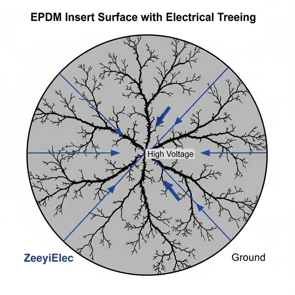
The physical evidence of partial discharge is undeniable to a trained technician. During a de-energized inspection, the primary indicator is “tracking.” This appears as distinct, branching black lines—often described as “treeing”—burned directly into the surface of the insert’s EPDM rubber or etched into the corresponding epoxy well wall.
These tracks are essentially permanent conductive pathways composed of carbonized insulation material. They typically originate near the high-voltage copper stud and propagate outward toward the grounded collar of the well. Once a carbon track forms, the interface’s dielectric strength drops precipitously. The presence of any visible tracking mandates the immediate replacement of the insert; the damage is irreversible and will inevitably lead to a catastrophic phase-to-ground flashover if the transformer is re-energized.
Figure 2: Carbon tracking (treeing) follows the path of least resistance across the interface, eventually leading to phase-to-ground flashover.
Mechanical Failures: Cross-Threading and Over-Torquing
While thermal and dielectric degradation often take months to manifest, mechanical failures are immediate and typically occur during the initial installation or subsequent maintenance switching. Diagnosing a mechanical failure requires field personnel to recognize the physical symptoms of improper handling, specifically involving the threaded 200A interface and the application of lubricants.
Signs of Cross-Threaded Copper Studs
The most frequent mechanical error is cross-threading the internal 3/8″-16 UNC copper stud into the transformer’s epoxy well. Field technicians should always begin threading by hand for the first two to three complete rotations. If resistance is felt immediately and a wrench is applied to force the connection, the copper threads will permanently deform.
During a post-failure teardown, a cross-threaded insert is easy to identify. The copper stud will show severely flattened or sheared threads on one side. Furthermore, the base flange of the EPDM rubber insert will sit asymmetrically against the epoxy well, leaving a visible gap. This asymmetrical seating guarantees that the internal electrical contacts are not fully engaged, creating an immediate high-resistance fault path.
Identifying Epoxy Well Micro-Fractures
Over-torquing is equally destructive. When installers use uncalibrated wrenches or pneumatic impact drivers, they often exceed the strict 10 to 15 ft-lbs (13.5 to 20.3 Nm) limit required for and insert interfaces. The immense rotational force transfers directly into the rigid epoxy of the transformer well.
Field diagnosis of an over-torqued interface often reveals micro-fractures radiating outward from the threaded receptacle in the well. These hairline cracks compromise the structural integrity of the entire transformer tank seal, allowing dielectric oil to leak out and moisture to enter, leading to catastrophic internal failure.
The Hydraulic Lock Effect
A subtler mechanical failure arises from the misapplication of dielectric grease. While a thin layer is mandatory to prevent air voids, packing the well with excessive silicone grease creates a “hydraulic lock.” As the insert is threaded inward, the incompressible grease cannot escape, building immense internal fluid pressure.
This pressure physically prevents the insert from fully seating, even if the torque wrench clicks at 15 ft-lbs. The technician believes the insert is tight, but the copper stud has not achieved the required metal-to-metal contact. Upon removal, a hydraulically locked insert will often feature a thick plug of grease packed into the base of the well, confirming that the torque reading was false and the interface was left dangerously loose.
[Expert Insight: Detecting Hydraulic Lock in the Field]
A classic sign of hydraulic lock is an insert that feels “spongy” during the final torque phase, rather than coming to a hard, defined mechanical stop.
If you back out a newly installed insert and hear a distinct suction sound or pop, excessive grease has formed a sealed vacuum chamber, confirming a hydraulic lock scenario.
Grease extruded heavily around the grounding collar immediately after torquing is a visual red flag that too much lubricant was applied to the mating surfaces.
Step-by-Step Field Diagnostic Workflow
When a 200A loadbreak interface fails or exhibits warning signs, a structured diagnostic workflow is mandatory to prevent secondary equipment damage and ensure personnel safety. Randomly pulling elbows or arbitrarily re-torquing inserts obscures the root cause and often exacerbates the underlying fault. This phased approach aligns with standard maintenance protocols for medium-voltage separable connectors, ensuring accurate assessment before component replacement.
Stage 1: De-Energized Visual Inspection
The diagnostic process begins only after the transformer is completely de-energized, isolated, and properly grounded. The initial visual inspection focuses on the exterior of the bushing well insert and the surrounding epoxy well.
Technicians must scan for any asymmetrical gap ≥ 1 mm at the seating collar where the EPDM rubber meets the transformer tank. This gap immediately indicates cross-threading or hydraulic lock. Next, inspect the exposed surface of the rubber for carbon tracking (faint black lines) and “chalky” thermal degradation, which signifies that the internal operating temperature has exceeded 130°C.
Stage 2: Mechanical Integrity Pull-Test
Before attempting to unthread the insert, perform a gentle mechanical pull-test. Apply approximately 10 to 15 lbs of lateral force to the insert’s nose. If the assembly exhibits rotational play or wobbles, the internal 3/8″-16 UNC copper threads are either severely under-torqued or mechanically sheared. This confirms that the critical metal-to-metal contact at the base has been lost, causing elevated internal resistance.
Stage 3: Advanced Electrical Diagnostics
If the visual and mechanical checks are inconclusive, advanced electrical testing is required before returning the equipment to service. The primary diagnostic is a micro-ohm resistance test across the interface.
Using a specialized micro-ohmmeter, measure the resistance from the transformer’s internal secondary (if accessible) to the insert’s primary contact. A healthy 200A interface should measure between 50 μΩ and 100 μΩ. Readings significantly higher than this baseline—or unstable readings that fluctuate during the test—confirm internal contact degradation. Finally, if the equipment is still energized and under load prior to the outage, ultrasonic detectors can identify the high-frequency acoustic emissions of partial discharge, pinpointing corona activity within the interface long before carbon tracking becomes visible on the exterior [VERIFY STANDARD: IEEE Std C57.12.90 for standard test codes].
Figure 3: A structured diagnostic workflow ensures that visual, mechanical, and electrical evidence is preserved for root cause analysis.
Sourcing High-Reliability Bushing Well Inserts
Diagnosing a field failure is only the first phase of network recovery; preventing a recurrence requires specifying replacement components that can withstand long-term thermal and dielectric stress. When an interface fails due to poor material stability or dimensional inaccuracies, replacing it with an identical low-tier component guarantees a repeat outage.
Preventing these failures starts at the procurement level. Engineers and procurement teams must specify 200A bushing well inserts manufactured with high-grade EPDM rubber formulations that resist thermal degradation under continuous load. Furthermore, the mechanical interface must be flawless to ensure a proper interference fit.
The internal 3/8″-16 UNC copper threads must be precision-machined so they can sustain the mandatory 10 to 15 ft-lbs (13.5 to 20.3 Nm) of seating torque without yielding or stretching. If the copper alloy is too soft, the threads will deform during installation, permanently compromising the contact resistance and introducing ΔT escalation that degrades the surrounding insulation over time.
ZeeyiElec engineers and manufactures high-reliability transformer accessories, including precision bushing well inserts designed for 15kV, 25kV, and 35kV distribution networks. Our production process prioritizes strict dimensional tolerances and rigorous dielectric testing to ensure every insert provides a corona-free, low-resistance interface right out of the box. We support OEM, EPC, and utility projects globally with fast technical matching, complete export documentation, and customized specification support. Consult ZeeyiElec’s engineering team today to secure dependable components and prevent premature interface failures on your next project.
Frequently Asked Questions
How can I tell if a bushing well insert is failing before an outage occurs?
Early-stage failures often present as elevated temperatures detectable during routine infrared (IR) thermography scans, typically showing a ΔT of 20°C or more compared to adjacent phases. Advanced diagnostics using ultrasonic detectors can also pinpoint high-frequency corona activity within the interface weeks before a catastrophic phase-to-ground fault happens.
What does carbon tracking look like on a removed insert?
Carbon tracking appears as distinct, branching black lines or “trees” burned directly into the surface of the EPDM rubber or the mating epoxy well. These tracks indicate that electrical stress (typically ≥15kV) has broken down the dielectric strength of the interface, creating a permanent conductive path that mandates immediate insert replacement.
Can a loose insert be re-torqued after it has been in service?
If an insert has been operating loosely and generating excessive heat (often exceeding the 130°C threshold of EPDM rubber), re-torquing is not a safe solution because the internal copper threads and insulation have likely suffered irreversible thermal degradation. The standard field practice is to completely remove the suspect insert, inspect the transformer well for damage, and install a brand-new component.
Why does an insert sometimes back out when the loadbreak elbow is removed?
An insert backing out during elbow removal usually indicates it was severely under-torqued (well below the required 10 to 15 ft-lbs) during initial installation, or cross-threading prevented the stud from locking securely. This mechanical failure requires the transformer to be de-energized immediately to replace the insert and inspect the well’s internal 3/8″-16 UNC threads.
Will applying more dielectric grease stop partial discharge?
No, applying excessive dielectric grease will not fix existing partial discharge and often introduces hydraulic lock, which physically prevents the insert from fully seating. Proper lubrication requires only a microscopic, uniform film (0.5 mm to 1.0 mm) to displace air; it cannot compensate for deep scratches, carbon tracks, or a lack of mechanical compression.
Is it necessary to test the transformer well if only the insert failed?
Yes, diagnosing an insert failure is incomplete without a meticulous visual and mechanical inspection of the permanent transformer well. If the well’s epoxy surface is scored by tracking or its internal copper threads are stretched from over-torquing, installing a new insert will simply result in a repeat failure within a short timeframe.
yoyo shi
Yoyo Shi writes for ZeeyiElec, focusing on medium-voltage accessories, transformer components, and cable accessory solutions. Her articles cover product applications, technical basics, and sourcing insights for global electrical industry buyers.