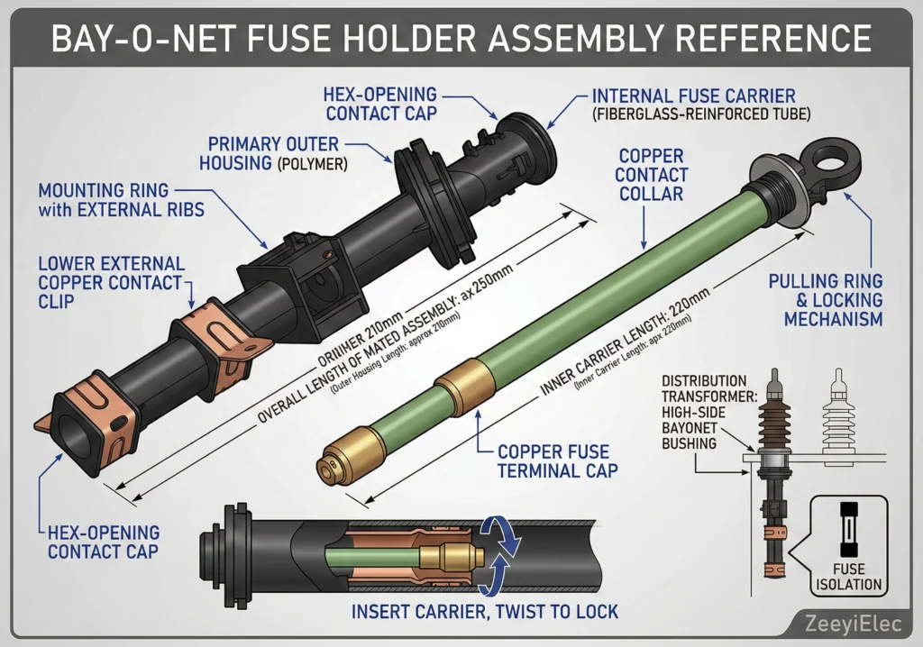
The selection of a Bay-O-Net fuse is a critical exercise in coordinated system protection. In modern distribution transformer design, particularly for oil-immersed units, the Bay-O-Net assembly serves as the primary “weak link” designed to protect the transformer from damaging overloads and secondary faults. Unlike a standard power fuse, the Bay-O-Net is part of a two-fuse protection philosophy where it handles low-magnitude currents, while a backup current-limiting fuse resides deeper in the circuit to clear high-magnitude catastrophic faults.
Figure 1:A detailed scientific cross-section of a Bay-O-Net fuse assembly illustrating the relationship between the inner fuse holder, silver-plated contacts, and the surrounding dielectric oil environment.
Defining the Primary Protection Boundary
The Bay-O-Net fuse operates within a specific “clearing zone.” Its primary responsibility is to detect and interrupt currents that exceed the transformer’s thermal limits but remain below the high-stress threshold of the internal windings. For instance, in a typical 15000V (15kV) distribution system, the Bay-O-Net is often sized to respond to currents in the 5A to 100A range. If a fault occurs on the secondary side, the Bay-O-Net element must melt before insulation reaches critical degradation temperatures, as governed by IEEE C57.91.
Why Capacity Determines the Fuse Link Choice
Transformer capacity (kVA or MVA) dictates the continuous rated current ($I_{rated}$) that transformer accessories must withstand. If the fuse rating is too close to the rated current, the element may fatigue due to cyclic loading. Conversely, if the rating is too high, the “protection tail” of the time-current curve (TCC) shifts too far to the right, leaving the transformer vulnerable to long-duration faults that can lead to tank bulging. In field commissioning, improper kVA-to-fuse matching is a leading cause of nuisance blowing during peak summer loads when oil temperatures reside near 60°C.
The relationship between transformer capacity (kVA), system voltage (kV), and the required fuse current (I) is defined by the standard power equation:
For Three-Phase: I = kVA / (√3 × kV)
For a 500kVA transformer at 13.8kV, the rated current is approximately 20.9A. Selection logic dictates choosing a fuse link with a minimum melt current that accounts for a 1.5× to 2× overload factor to accommodate transient peaks.
Step 1: Mapping Transformer kVA to Rated Secondary Current
The first stage in selecting a bay-o-net fuse assembly involves translating nameplate capacity into primary full-load current (FLC). This provides the baseline for the fuse link rating.
Single-Phase kVA Calculation Method
For single-phase distribution transformers, the primary current is the quotient of capacity (kVA) and primary system voltage (kV). For a common 14.4kV primary system with a 50kVA unit, the FLC is 3.47A. Field experience suggests applying a multiplier of 1.4× to 2.0× FLC to determine the fuse rating, preventing nuisance blowing from magnetizing inrush current, which can spike up to 12 times FLC.
Three-Phase Delta vs. Wye Current Factors
Three-phase systems require the square root of three constant (√3 ≈ 1.732). Neglecting this factor leads to over-fusing, which can prevent the clearing of low-magnitude faults and result in internal transformer damage.
The standard formula for primary full-load current (Ip) used to size the fuse is:
Ip = kVA / (VL-L × 1.732)
Example: For a 750kVA three-phase unit at 12.47kV:
Ip = 750 / (12.47 × 1.732) = 34.72A
Voltage Class Multipliers (15kV vs. 25kV)
System voltage drastically affects required amperage. A 1000kVA transformer at 15kV carries approx. 38.5A, whereas at 25kV it carries approx. 23.1A. Ensure the assembly is rated for the system’s Basic Insulation Level (BIL). According to IEEE C57.12.00, a 15kV system typically requires 95kV BIL, while a 25kV system requires 150kV BIL.
[Expert Insight: FLC Calculation]
Primary Focus: Always calculate FLC on the high-voltage side.
Inrush Margin: Ensure the fuse can withstand 12× FLC for 0.1s.
Delta vs. Wye: Verify the primary configuration to account for zero-sequence fault detection.
Step 2: Selecting the Fuse Link Type (Current Sensing vs. Dual Sensing)
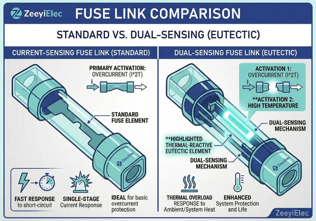
Choosing between current-sensing and dual-sensing links depends on the desired level of thermal protection. Both fit the same bay-o-net fuse assembly but use different metallurgical properties.
Figure 2:Comparison infographic contrasting the response curves of current-sensing and dual-sensing fuse links, highlighting the eutectic alloy’s reaction to both current and oil temperature.
Physics of the Dual-Sensing Element
The dual-sensing link features a eutectic alloy element calibrated to react when oil temperature reaches 140°C to 150°C. These are the gold standard for pad-mounted units in high-ambient regions, as they provide a thermal “safeguard” for internal insulation.
Application Scenarios for Current-Sensing Links
Current-sensing links are preferred for transformers subject to frequent, short-duration peak loads that might cause nuisance trips in dual-sensing units. They offer stability in standard utility networks where units are conservatively loaded (e.g., 50kVA-167kVA).
Characteristic Comparison Table
Feature
Current-Sensing (CS)
Dual-Sensing (DS)
Primary Trigger
Amperage Magnitude
Amperage + Oil Temperature
Typical Range
3A to 140A
3A to 140A
Overload Sensitivity
Low (Fault focused)
High (Thermal focused)
The choice must be cross-referenced with your coordination study. IEEE C37.41 requires testing expulsion-type fuses within the specific thermal environment of the fluid-filled enclosure.
Step 3: Core Selection Chart by Transformer Capacity
The following matrices provide a baseline for matching fuse links to common capacities.
15kV Class Fuse Rating Matrix (10kVA – 500kVA)
For a 50kVA single-phase unit, a 6A to 10A link is common. A 500kVA three-phase unit typically requires a 40A to 65A rating.
Typical 15kV Selection Guide (Current-Sensing)
Trans. Capacity (kVA)
Voltage Class (kV)
Suggested Fuse Rating (A)
25 (1-Ph)
14.4
3 – 5 A
75 (3-Ph)
12.47
8 – 12 A
500 (3-Ph)
13.2
40 – 65 A
Handling High-Capacity Pad-Mounted Units
For units between 750kVA and 2500kVA, the selection is more complex. It is recommended to verify the “crossover” with a backup current limiting fuse. [VERIFY STANDARD: IEEE C57.12.00 for tank pressure limits].
Coordinating with Backup Current Limiting Fuses
The bay-o-net fuse assembly interrupting capacity is approx. 3,500A at 15kV. To protect against high-magnitude faults up to 50,000A, a current limiting fuse is installed in series.
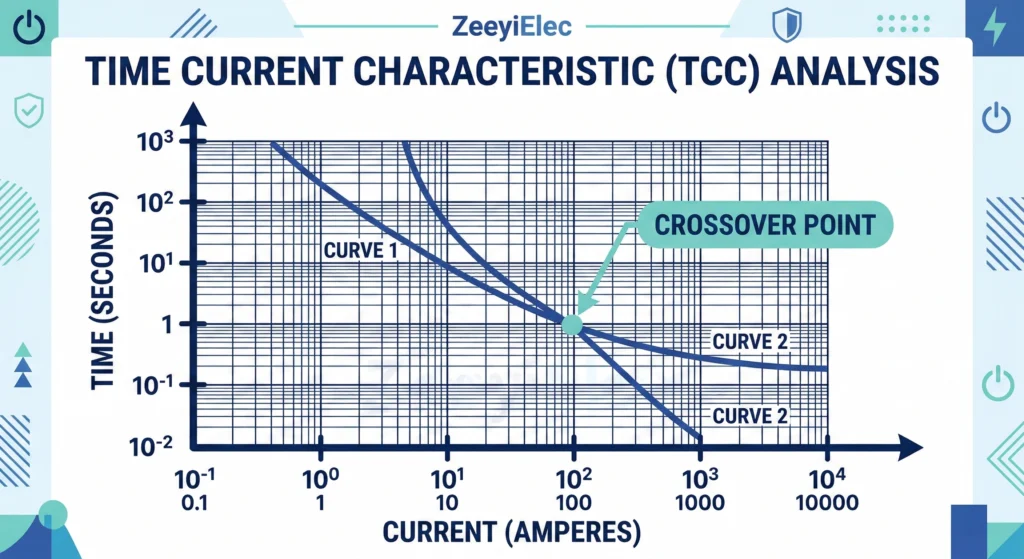
Figure 3:Time-current curve (TCC) analysis showing the coordination between a Bay-O-Net expulsion fuse and a backup current-limiting fuse to ensure full-range protection.
The “Crossover” Point Calculation
Coordination is successful when TCC curves intersect at a specific crossover point. If this point is too high, the Bay-O-Net may attempt to clear a fault exceeding its limits, leading to internal pressure spikes.
To verify coordination, ensure the following condition is met:
Icrossover < Iinterrupting_rating_bayonet
Field Realities: Derating for Ambient Temperature and Altitude
Standard ratings assume 25°C ambient air. Deviations can drive premature aging or flashover.
Derating for High-Ambient Oil Temperatures
In desert climates where oil reaches 80°C to 100°C, a fuse will melt at lower current. A general rule suggests 1% derating for every 1°C increase above 25°C for dual-sensing links.
Altitude Adjustments for External Flashover Distance
Decreased air density at altitudes >2,000m increases external flashover risk. Check medium voltage bushings against IEEE C37.40 derating factors.
[Expert Insight: Field Installation]
Lubrication: Use approved silicone grease on O-rings for moisture seals.
Contacts: Pitting on silver-plated contacts increases resistance and local heating.
Altitude: Above 3,300ft (1000m), verify strike distance to grounded tank walls.
Primary System Voltage: Nominal voltage (e.g., 12.47kV).
Fuse Link Type: Current-Sensing or Dual-Sensing.
Voltage Class / BIL: Housing match (95kV or 150kV BIL).
Verifying Compatibility with Existing Well Inserts
Verify the interface between the fuse holder and bushing well inserts. Contact tension is essential for long-term reliability.
ZeeyiElec supports complex accessory RFQs with model matching and export documentation. Request a Quote for your project requirements today.
Frequently Asked Questions
Can a Bay-O-Net fuse be oversized to prevent inrush blowing?
Oversizing beyond 2.0× FLC risks leaving the transformer unprotected against overloads, leading to winding insulation failure before the fuse melts.
What is the typical life expectancy of a Bay-O-Net assembly?
The assembly housing and inner holder typically serve for 20-30 years unless carbon tracking occurs from high-voltage flashover.
Do 35kV systems use the same Bay-O-Net assemblies as 15kV?
No, 35kV systems require assemblies with 150kV or 200kV BIL ratings and longer creepage distances to prevent phase-to-ground breakdown in oil.
Why do dual-sensing links trip more often in the summer?
They are calibrated to oil temperature; higher ambient temperatures reduce the current required to reach the element’s eutectic melting point.
How often should Bay-O-Net contacts be inspected?
Visually inspect for silver-plating degradation or pitting during routine maintenance or every time a fuse link is replaced.
Is a current-limiting fuse necessary with a Bay-O-Net?
Yes, for systems with fault currents >3,500A, a current-limiting backup fuse prevents the Bay-O-Net from exceeding its mechanical design limits.
yoyo shi
Yoyo Shi writes for ZeeyiElec, focusing on medium-voltage accessories, transformer components, and cable accessory solutions. Her articles cover product applications, technical basics, and sourcing insights for global electrical industry buyers.