When procuring components for distribution transformers, an incomplete Request for Quotation (RFQ) creates a ripple effect that extends far beyond the purchasing department. A missing dimensional specification or an ambiguous voltage class does not just delay the supplier’s quotation; it introduces critical mismatch risks at the installation site.
Consider a common scenario: a procurement team requests a standard “15kV insert” without specifying the interface dimensions or the exact insulation level. The supplier manufactures a component rated for a 95 kV Basic Impulse Level (BIL). Weeks later, the units arrive on site. The field engineering team, however, is commissioning a dual-rated 15/25 kV system that strictly requires a 125 kV BIL for adequate surge protection. The entire batch is rejected during pre-energization inspections, project timelines stall, and the utility faces unexpected change-order costs.
Field data consistently shows that missing mechanical constraints—such as failing to define the hold-down bail tab orientation or specifying an incorrect 200A loadbreak interface geometry—account for ≥ 40% of installation delays involving حشوات آبار البطانات. When the insert’s molded EPDM rubber does not mate perfectly with the transformer’s universal well or the incoming cable’s elbow, the dielectric seal is compromised. Moisture ingress becomes inevitable, leading to tracking and eventual insulation failure under continuous loads of 200A or short-circuit conditions reaching 10kA symmetrical.
To eliminate these costly field failures, engineers and buyers must structure their RFQs to leave no room for supplier assumptions.
Core Categories of a Complete Bushing Well Insert RFQ
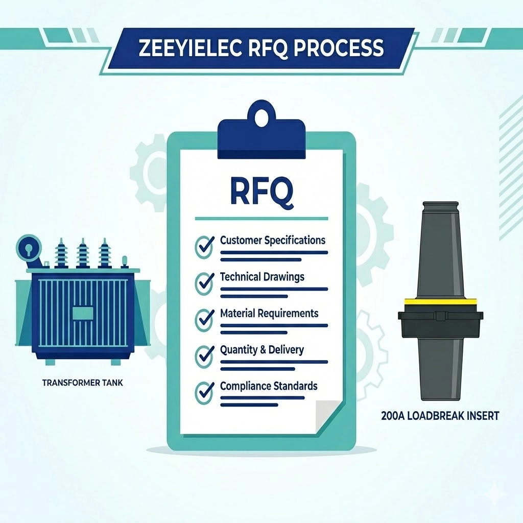
For immediate clarity and to prevent supply chain bottlenecks, a proper RFQ must explicitly detail data across four main categories:
The exact system voltage, continuous current capacity, short-circuit withstand ratings, and required BIL.
Compatibility dimensions for standard 200A loadbreak elbows and the primary universal well.
Primary insulation material formulation, semi-conductive shielding specifications, and the internal contact metals.
Required routine tests (such as partial discharge limits) and relevant type test certifications.
Core Electrical Specifications: Voltage & Current Classes
The foundation of any successful procurement checklist for transformer components begins with defining the electrical operating envelope. Specifying a generic voltage class is insufficient; the RFQ must explicitly correlate the nominal system voltage with the required insulation withstand levels and fault-clearing capabilities to prevent catastrophic dielectric failure.
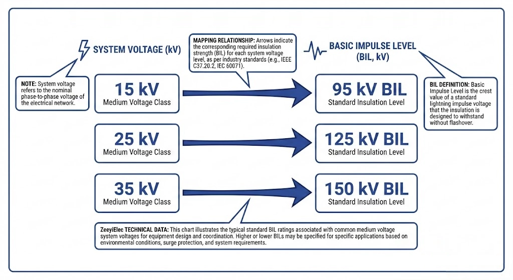
Figure 01:Correlating nominal system voltage with required BIL and AC withstand guarantees adequate dielectric protection against network surges.
System Voltage & BIL Requirements
When defining the voltage parameters, engineers must specify three distinct values: the nominal system voltage, the maximum line-to-ground voltage, and the Basic Impulse Level (BIL). For standard distribution networks, bushing well inserts are typically categorized into 15kV, 25kV, and 35kV classes.
Utility specifications often demand dual-rated components to simplify inventory and increase safety margins. For example, a 15/25kV loadbreak insert must be designed to handle a maximum voltage rating of 15.2 kV line-to-ground and 26.3 kV line-to-line. The RFQ must dictate the required BIL to ensure adequate protection against lightning strikes and switching surges. A standard 15kV application requires a BIL of ≥ 95 kV, while a 25kV application demands ≥ 125 kV. For 35kV distribution transformers, the insulation architecture must successfully withstand a BIL of ≥ 150 kV alongside a 60 Hz AC withstand voltage of 50 kV for one minute.
Continuous & Short-Circuit Current Ratings
The current rating section of your checklist must account for both normal thermal operating conditions and maximum network fault scenarios. The industry-standard continuous current rating for loadbreak bushing well inserts is 200A. This rating indicates the maximum steady-state load the internal contacts can carry without exceeding their permissible temperature rise limits.
Beyond the continuous rating, the RFQ must explicitly state the required short-time current withstand capabilities. During a system fault, the insert must maintain its mechanical and electrical integrity until upstream protection devices, such as صمامات الحد من التيار, clear the circuit. A rigorous specification requires the 200A interface to successfully withstand a short-circuit current of 10 kA symmetrical for 0.17 seconds (approximately 10 cycles). Engineers must also specify the momentary make-and-latch rating, typically mandated at ≥ 10 kA asymmetrical. This ensures that field operators can safely close a mating loadbreak elbow onto a faulted circuit without risking catastrophic structural failure or arc flash blowouts.
Expert Insight: BIL Verification
Never assume a 15kV rating automatically implies a 95kV BIL. Coastal and high-lightning areas routinely specify 15kV class equipment with 125kV BIL inserts to prevent impulse tracking across the insulation interface.
Expert Insight: Fault Current Coordination
Ensure the 10kA asymmetrical make-and-latch rating of the insert matches or exceeds the let-through energy of the upstream protection fuse, preventing explosive mechanical failures during fault-closures.
Interface Dimensions & Mechanical Compatibility
The dimensional specifications of a 200A loadbreak interface are unforgiving. If an RFQ omits mechanical tolerances, the resulting components may experience improper mating, leading to poor electrical contact, compromised dielectric sealing, and eventual catastrophic failure during switching operations or load cycling. Procurement teams must define three critical mechanical connection points to guarantee universal compatibility.
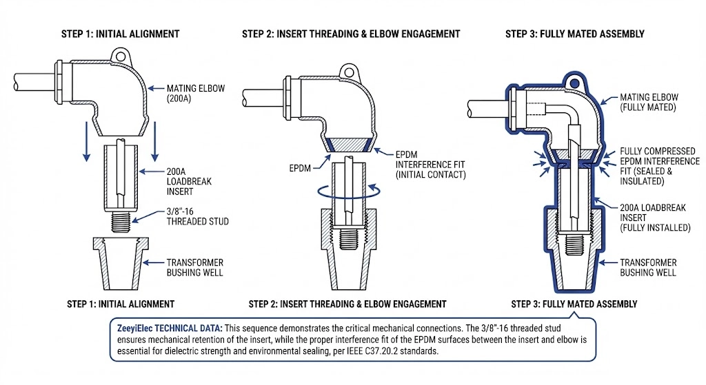
Figure 02:The mechanical mating interface relies on exact IEEE 386 dimensional tolerances to maintain a flawless dielectric seal.
The Transformer Bushing Well Interface
The primary mechanical connection occurs where the insert threads into the universal bushing well mounted on the transformer tank. This internal interface must withstand significant torque during installation and provide a flawless dielectric seal.
Your RFQ must mandate that the insert’s threaded stud and molded EPDM base adhere precisely to the dimensional requirements of IEEE Std 386™ for 200A universal wells. Specify the required thread pitch, typically 3/8″-16 UNC-2A copper or copper-alloy threads. The torque limits for seating the insert must also be defined, usually between 10 ft-lbs and 15 ft-lbs (13.5 N·m to 20.3 N·m). If the threads gall or the EPDM base is dimensionally oversized, the insert will fail to seat fully, creating a void that inevitably leads to partial discharge tracking across the primary insulation.
The Loadbreak Elbow Mating Interface
The external portion of the insert forms the female connection point for a mating 200A loadbreak elbow. This interface is responsible for both the primary current transfer and the environmental seal that prevents moisture ingress into the connection.
The RFQ must specify the exact geometry of this interface, ensuring strict compliance with IEEE 386 standard dimensions for 15kV, 25kV, or 35kV class loadbreak connectors. Key parameters include the internal contact finger cluster diameter, the depth of the arc-snuffing chamber, and the interference fit of the molded EPDM rubber. A properly specified interface will require an insertion force of 50 lbs to 120 lbs (222 N to 533 N) and a withdrawal force of 50 lbs to 120 lbs to ensure the elbow remains securely seated during load cycling and switching operations. An incorrect interference fit allows the elbow to back off, leading to catastrophic arc flash events during operation.
Bail Assembly & Fastening Requirements
A frequently overlooked specification in bushing well insert procurement is the mechanical hold-down mechanism. The RFQ must define the required bail assembly configuration. Does the existing transformer well utilize a bolt-on bail plate, integrated bail tabs, or a specialized hold-down bracket?
If the insert is intended for an existing fleet, the RFQ should specify compatibility with the current bail hardware to prevent the elbow from dislodging under the mechanical stress of a fault or the physical strain of heavy cable runs. Request details on the insert’s molded bail tabs, ensuring their thickness and orientation align with standard industry hold-down bails.
Expert Insight: Torque Trap
Over-torquing the 3/8″-16 stud past 15 ft-lbs will shear the copper rod inside the EPDM housing. Always specify maximum seating torque in the RFQ to hold manufacturers accountable to structural limits.
Expert Insight: Bail Tab Alignment
Missing bail tab specs account for massive field frustrations. Specify whether you need fixed molded tabs or an adjustable bail ring, especially if retrofitting older transformer tanks.
Material Composition & Environmental Resilience
A bushing well insert is only as reliable as the materials forming its insulation and conductive paths. When an RFQ uses generic terms like “rubber” or “metal contacts,” it invites suppliers to substitute inferior materials that degrade rapidly under electrical stress, temperature fluctuations, and environmental contamination. Specifying exact material properties is non-negotiable for long-term dielectric stability.
Insulation Material (EPDM & Semi-Conductive Shielding)
The primary insulation body must withstand decades of continuous high voltage and thermal cycling without losing its dielectric strength or mechanical elasticity. Your RFQ must specify high-quality, peroxide-cured EPDM (Ethylene Propylene Diene Monomer) rubber. This specific curing process is critical; sulfur-cured rubbers often exhibit inferior tracking resistance and faster thermal aging.
The insert must also feature an integrated, molded semi-conductive EPDM shield. This shield serves two critical functions: it manages the electrical stress field at the mating interfaces and provides an unbroken ground plane for dead-front safety. The RFQ should require the semi-conductive shield to maintain a volume resistivity of ≤ 5000 Ω·cm. If the resistivity exceeds this threshold, the shield cannot effectively conduct capacitive charging currents to ground, leading to dangerous voltage potentials on the surface of the insert and potential shock hazards for operating personnel.
Internal Conductor & Contact Materials
The internal current-carrying components must transfer 200A continuously without generating excessive heat that could degrade the surrounding EPDM insulation. The RFQ must specify the material for both the central conductor rod and the female contact fingers.
Specify high-conductivity, oxygen-free copper or a robust copper alloy for the internal contact structures. Avoid unplated aluminum contacts in this application due to their susceptibility to galvanic corrosion and higher contact resistance. Demand that the contact fingers feature a silver or tin plating (≥ 5 μm thickness) to ensure a stable, low-resistance interface with the mating elbow probe, even after repeated loadbreak operations.
Operating Temperature & Altitude Adjustments
Environmental operating conditions dramatically impact dielectric performance. Standard inserts are designed for sea-level operation at ambient temperatures. If your project is located in an extreme environment, the RFQ must explicitly state these conditions to ensure the supplier provides appropriately rated components.
If the installation site exceeds 1000 meters (3300 feet) above sea level, the dielectric strength of the surrounding air decreases. The RFQ must specify the site altitude so the manufacturer can apply appropriate de-rating factors or supply a higher voltage-class insert (e.g., using a 25kV insert in a 15kV application) to compensate for the reduced atmospheric pressure. Define the required operating temperature range, typically -40°C to +65°C ambient, to ensure the EPDM rubber retains its flexibility and sealing properties in severe cold and resists accelerated thermal degradation in extreme heat.
Factory Testing & Compliance Documentation
A completed RFQ is only as strong as the documentation required to verify the finished product. Without explicit testing mandates, procurement teams risk receiving components that look correct but contain hidden dielectric flaws. A robust RFQ must demand both routine production test reports for the specific batch being ordered and comprehensive type test certificates validating the product’s underlying design.
Routine Production Tests (AC Withstand & Partial Discharge)
Routine tests are non-destructive evaluations performed on every single insert before it leaves the factory. Your RFQ must explicitly require the supplier to provide these test reports with the shipment.
The two most critical routine tests are the AC withstand voltage test and the partial discharge (PD) measurement. For a standard 15kV class insert, the RFQ should mandate a 60 Hz AC withstand test at 34 kV for one minute to ensure gross insulation integrity. However, the AC withstand test cannot detect microscopic voids within the EPDM rubber. Therefore, the RFQ must strictly demand a partial discharge test, requiring the insert to exhibit ≤ 3 pC of discharge at a specified test voltage (e.g., 11 kV for a 15kV system). Any value exceeding 3 pC indicates internal manufacturing defects that will inevitably lead to electrical tracking and catastrophic failure in the field.
Type Test Reports & Certification
While routine tests verify individual units, type test certificates validate the fundamental engineering design and material selection of the insert family. These are exhaustive, often destructive tests performed on a representative sample of the product line.
Your RFQ must require the supplier to submit valid type test reports from an accredited independent laboratory, confirming compliance with [VERIFY STANDARD: IEEE 386 or IEC 60502-4] requirements for separable insulated connector systems. Request documentation proving the insert has successfully passed the loadbreak cycling test (typically 10 make-and-break operations at 200A) and the fault-closure test (withstanding a 10 kA symmetrical fault current for 0.17 seconds). Demand the thermal cycling and accelerated aging test results to confirm the EPDM insulation will maintain its dielectric properties over a projected 25-to-30-year service life.
The Master Bushing Well Insert RFQ Template
Translating rigorous engineering requirements into a procurement document is often where critical data is lost. In international supply chains, structuring technical data exactly how OEM manufacturers process it eliminates weeks of back-and-forth Request for Information (RFI) loops. The following template consolidates the electrical, mechanical, and compliance specifications into a universally understood, copy-pasteable format.
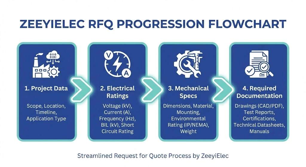
Figure 03:Following a structured evaluation sequence prevents critical specification gaps before the purchase order is finalized.
1. General Project Data
Define the operational reality. The supplier needs to know if the component is going into a climate-controlled indoor substation or a harsh, high-altitude outdoor environment.
Target Application: Pad-mounted distribution transformer, submersible vault, etc.
Operating Environment: Ambient temperature -40°C to +65°C, Altitude > 1000m.
Expected Contamination: Heavy coastal salt fog, industrial dust, etc.
2. Electrical Ratings
This section dictates the core dielectric and current-carrying capabilities of the interface. Specify the nominal system voltage alongside the required Basic Impulse Level (e.g., 15/25 kV dual-rated with ≥ 125 kV BIL). Define the continuous current (standard 200A) and the short-time fault current withstand (e.g., 10 kA symmetrical for 0.17 seconds). Include the required AC 60 Hz 1-minute withstand voltage to ensure baseline insulation strength.
3. Mechanical & Interface Specs
Map out the physical connections to ensure the insert mates perfectly with both the transformer tank and the incoming cable elbows. Demand compliance with the standard 200A loadbreak interface dimensions. Explicitly state the bushing well stud thread requirement (typically 3/8″-16 UNC-2A) and the maximum seating torque rating (≤ 15 ft-lbs). Specify the bail assembly configuration—state whether your fleet uses integrated bail tabs or requires an external hold-down plate to secure the elbow.
4. Required Documentation & Shipping
Lock in your quality assurance before the purchase order is finalized. Mandate that routine factory test reports must accompany every shipment, specifically verifying that partial discharge levels are ≤ 3 pC at the rated test voltage. Require the submission of valid type test certificates for the specific design. Finally, when importing ملحقات المحولات internationally, specify exact export packaging requirements to prevent mechanical deformation of the EPDM rubber housing during ocean freight or rough site handling.
Sourcing OEM/ODM Bushing Well Inserts for Your Project
Procuring reliable distribution transformer interfaces requires a manufacturing partner who understands both grid-level dielectric stress and international supply chain logistics. A perfectly structured RFQ loses its value if the manufacturer cannot provide the necessary compliance paperwork or fails to execute rigorous routine testing.
At Wenzhou Zeeyi Electric, we specialize in the engineering and production of medium-voltage accessories for global utility and EPC projects. Whether your distribution network operates at a standard 15kV class or demands dual-rated 15/25kV components capable of withstanding a 125kV BIL, our production facilities ensure strict alignment with [NEED AUTHORITY LINK SOURCE: IEEE Std 386™ specification for separable insulated connector systems].
We provide comprehensive OEM/ODM customization to match specific tank geometries, bail tab orientations, and 200A loadbreak elbow constraints. To eliminate procurement friction and prevent customs delays, our team supplies complete export documentation alongside routine factory acceptance test reports for every batch.
We guarantee that our supplied components are verified to exhibit partial discharge levels of ≤ 3 pC before any shipment leaves our facility, ensuring decades of stable field performance. Submit your completed RFQ parameters and mechanical drawings to our engineering team for fast technical evaluation, model matching, and exact quotation support across our complete portfolio of transformer and ملحقات الكابلات.
الأسئلة المتداولة
What is the standard current rating for a distribution bushing well insert?
The standard continuous current rating is 200A for normal thermal operation, though the interface must also withstand a 10 kA symmetrical short-circuit fault for 0.17 seconds to ensure structural integrity until upstream protection clears the fault.
Can a 25kV insert be used in a 15kV transformer system?
Yes, specifying a 25kV dual-rated insert (125kV BIL) for a 15kV system is a standard engineering practice that increases dielectric safety margins against switching surges. However, utilizing a 15kV-only component in a 25kV network will cause rapid insulation breakdown.
How do you specify the bail assembly in an RFQ?
An RFQ must explicitly define whether the installation requires an integrated bail plate, molded bail tabs, or external hold-down bails. This mechanical constraint is dictated by the transformer tank’s existing hardware and is mandatory to prevent the elbow from dislodging under fault stress.
What is the acceptable partial discharge limit for a 200A insert?
A 200A loadbreak insert must exhibit a partial discharge level of ≤ 3 pC at its designated test voltage (e.g., 11kV for a 15kV class interface). Values exceeding this 3 pC threshold indicate microscopic voids within the EPDM rubber that will inevitably cause premature dielectric tracking.
Do bushing well inserts come with the bushing well itself?
No, the universal bushing well (mounted to the tank) and the loadbreak insert (the removable interface) are specified and procured as independent line items. Procurement teams must request the “insert” specifically while detailing the existing well’s 3/8″-16 UNC-2A threaded stud to guarantee mating compatibility.
What material is typically specified for the outer housing of an insert?
The primary insulation housing must be specified as high-quality, peroxide-cured EPDM rubber jacketed with a molded semi-conductive EPDM shield. This composition maintains critical mechanical flexibility from -40°C to +65°C while providing an unbroken ground plane for dead-front operator safety.
يويو شي
تكتب يويو شي في ZeeyiElec، مع التركيز على ملحقات الجهد المتوسط ومكونات المحولات وحلول ملحقات الكابلات. تغطي مقالاتها تطبيقات المنتجات، والأساسيات التقنية، ورؤى المصادر للمشترين العالميين في مجال الصناعات الكهربائية.