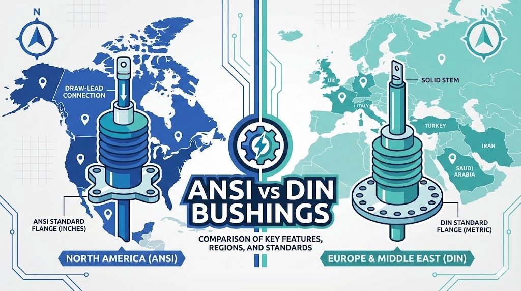
The division between ANSI and DIN standards is not merely a geographic preference; it represents two fundamentally different engineering philosophies governing how high-voltage conductors penetrate grounded transformer tanks. For procurement teams and engineers sourcing transformer accessories, understanding this split is the first step in avoiding costly compatibility errors on the factory floor or at the installation site. In field deployments, installation crews routinely face project delays when a transformer engineered with a European DIN tank hole pattern is shipped to a utility expecting standard North American hardware. The resulting flange mismatch cannot be safely resolved with simple gaskets, forcing custom fabrication or complete component re-ordering that can derail project energization schedules by weeks.
Figure 01:Visual comparison highlighting the alternating shed profile typical of ANSI designs versus the uniform shed structure common in DIN standards.
The ANSI/IEEE Approach to Bushing Design
Rooted in the North American power grid’s historical development and diverse environmental extremes, the ANSI/IEEE framework ([NEED AUTHORITY LINK SOURCE] Anchor: IEEE C57.19.01 standard) prioritizes heavy-duty mechanical robustness and specific regional environmental adaptations. ANSI bushings, commonly specified in 15 kV, 25 kV, and 35 kV voltage classes, often utilize a draw-lead or bottom-connected architecture to handle significant mechanical stress from heavy conductor drops.
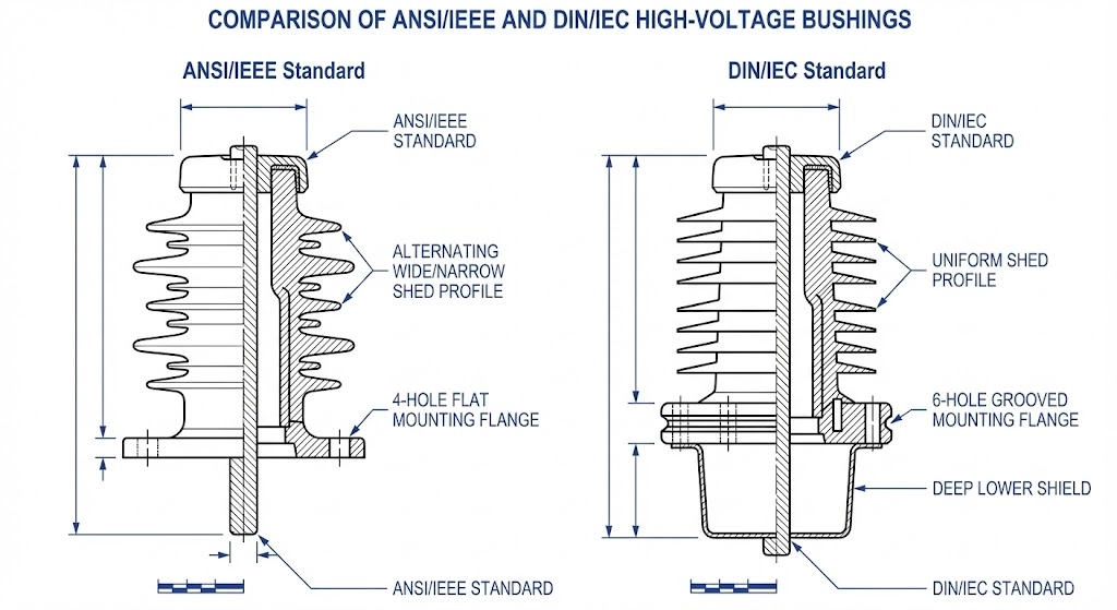
One of the most recognizable structural differences lies in the porcelain shed profile. ANSI designs frequently employ alternating shed diameters—a wide shed followed by a narrower shed. This structural choice is explicitly designed to break up water cascades during heavy rainstorms, preventing continuous conductive paths from forming across the insulator’s dielectric surface and mitigating flashover risks in coastal or high-precipitation zones.
The DIN/IEC Approach to Bushing Design
Conversely, the European-originated DIN standard (now largely harmonized under IEC 60137 and EN 50180) emphasizes strict modularity and universal dimensional interchangeability across manufacturers. When selecting medium voltage bushings under the DIN system, the dimensions of the mounting flange, the bolt circle, and the top terminal are rigidly standardized based on precise voltage and current ratings, such as 12 kV / 630 A or 24 kV / 250 A.
This highly regulated dimensional structure ensures that a DIN bushing from one global manufacturer will perfectly fit the tank cutout originally designed for a completely different supplier’s component, vastly simplifying European supply chains. Structurally, DIN porcelain insulators traditionally feature uniform shed profiles, relying on a larger overall height and precisely calculated surface distances to manage electrical stress and environmental contamination.
Dimensional and Mounting Architecture Differences
For procurement teams evaluating supplier quotes, the most immediate point of failure when mixing standards is mechanical incompatibility. A transformer tank manufactured to accommodate a European DIN cutout pattern cannot accept an ANSI standard component without expensive, custom-machined adapter plates. This dimensional mismatch extends beyond just the bolt holes—it fundamentally dictates how the accessory seals against the transformer oil and handles mechanical and thermal loads during its 30-year lifecycle.
Flange and Bolt Circle Variations
ANSI/IEEE mounting flanges prioritize flexible integration. They often utilize adjustable clamping rings or generalized 3-hole, 4-hole, and 6-hole mounting patterns that can vary slightly between manufacturers while still meeting the broader standard. The bolting hardware typically relies on imperial thread pitches, such as 1/2-13 UNC.
Conversely, DIN standards enforce strict, non-negotiable metric dimensions across the industry. For example, a standardized 12 kV / 630 A DIN bushing strictly dictates a 160 mm bolt circle diameter designed specifically for M12 mounting studs. There is zero tolerance for deviation; if a tank is drilled at 162 mm, the DIN component will not seat.
Architectural Feature
ANSI / IEEE Standard
DIN / EN Standard
Mounting Footprint
Variable by manufacturer (often utilizes slotted holes or external clamps)
Strictly standardized metric layouts (typically 4 or 6 rigid holes)
Measurement System
Imperial (inches)
Metric (mm)
Lower Internal Shielding
Often minimized or integrated smoothly with the core porcelain
Frequently features a pronounced lower shield requiring wider tank cutouts
Gasket and Sealing Mechanisms
Beyond the bolt circle, the physical interface where the porcelain meets the transformer tank wall dictates long-term environmental reliability. ANSI designs frequently rely on flat, compressed gaskets—such as nitrile rubber or cork-neoprene—sandwiched directly between a flat porcelain mounting base and the tank wall. These require specific, even torque application (often 30-40 Nm) to prevent cracking the porcelain while ensuring an oil-tight seal.
In contrast, DIN components often feature an integrated metal flange (usually cast aluminum or brass) permanently cemented to the porcelain body. This metal flange contains a precisely machined groove designed to capture a specifically sized NBR O-ring, often an 8 mm or 10 mm cross-section.
[Expert Insight]
Compressing a DIN O-ring requires significantly less torque (typically 15-20 Nm) than a flat ANSI gasket. Over-torquing a DIN flange to ANSI specifications frequently warps the cast aluminum ring, causing immediate field leaks.
Applying a flat cork-neoprene gasket to a DIN grooved flange will almost universally result in oil weepage once the transformer reaches its peak operational temperature of 65°C to 85°C and internal tank pressure increases.
When swapping standards, field crews often lack the correct imperial or metric studs, leading to dangerous cross-threading on the tank wall.
Electrical Stress Management and Creepage Profiles
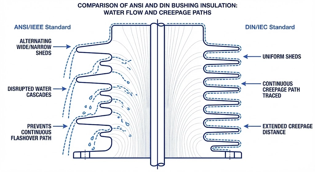
Beyond mechanical fit, a fundamental difference between ANSI and DIN specifications lies in how each dictates electrical stress distribution and environmental sealing across the insulator surface. The design philosophies for high-voltage insulation under IEEE C57.19.01 and IEC 60137 require different geometric approaches to managing surface currents, especially in highly contaminated environments.
Figure 02:Cross-section diagram showing how differing shed geometries manage electrical stress and dictate creepage distances under heavy environmental pollution.
Shed Profiles and Pollution Resistance
In outdoor transformer applications, the porcelain’s ability to resist pollution—salt spray, industrial soot, or agricultural dust—determines long-term reliability. As noted, ANSI standard designs historically favor an alternating shed profile to interrupt continuous water paths. This is highly effective in environments subjected to heavy, driving rain.
European DIN designs frequently employ uniform, equally spaced sheds. While older DIN iterations relied primarily on total height to achieve the required creepage distance, modern DIN components adhere to stringent specific creepage definitions based on pollution severity. Both standards generally agree on the necessary metrics, typically ranging from 16 mm/kV for light pollution environments up to 31 mm/kV for very heavy pollution, though the physical shape required to achieve those numbers varies significantly.
Basic Impulse Level (BIL) Ratings Comparison
The most critical electrical mismatch occurs when comparing Basic Impulse Level (BIL) ratings between the two standards. BIL dictates the accessory’s ability to withstand transient lightning or switching surges.
A direct voltage class translation does not guarantee equivalent impulse strength. For example, an ANSI-specified 15 kV bushing is almost universally tested to a 95 kV BIL. However, a nominally equivalent DIN component rated for 12 kV or 17.5 kV might only be tested to a 75 kV or 95 kV BIL depending on the specific IEC 60137 class ordered.
Procurement teams cannot assume a “15 kV class” designation implies universal transient protection. Specifying a DIN component with a lower BIL into an ANSI-designed network leaves the transformer vulnerable to lightning-induced insulation breakdown. Furthermore, the internal capacitance and dielectric stress grading—whether through simple oil-impregnated paper (OIP) or resin-impregnated paper (RIP)—is often engineered to match the specific BIL testing waveform defined by the native standard.
Interchangeability Realities in Field Replacements
The theory of global standardization often breaks down rapidly when a maintenance crew is standing over an open transformer tank in the field. The reality of replacing a failed ANSI bushing with a readily available DIN component—or vice versa—involves significant mechanical hurdles that cannot be solved with a simple parts substitution. While voltage and current ratings may theoretically align, the physical installation realities dictate whether the transformer can be returned to service safely and reliably.
The Problem with “Universal” Adapters
The most common field solution for standard mismatches is the use of adapter plates—custom-machined steel or aluminum discs designed to bridge the gap between a 4-hole ANSI tank pattern and a 6-hole DIN component, or to adapt imperial bolt spacing to metric dimensions.
A typical DIN 250 A flange features a 115 mm bolt circle requiring M10 studs. If a field engineer attempts to install this onto an older ANSI tank designed with a 4.5-inch (114.3 mm) bolt circle and 1/2-13 UNC imperial studs, the resulting misalignment is physically impossible to secure without an adapter plate.
However, relying on adapter plates introduces multiple failure points. First, the adapter necessitates two sealing surfaces—one between the tank and the adapter, and another between the adapter and the new bushing flange. This doubles the risk of oil leaks, especially under the thermal cycling inherent to transformer operation. Secondly, the adapter inherently raises the component’s mounting height, which can alter the external air clearance (striking distance) to grounded structures or adjacent phases, potentially violating safety margins.
Tank Hole and Internal Clearance Conflicts
The most severe compatibility issue arises below the mounting flange. ANSI and DIN designs allocate internal tank space differently.
Many modern DIN designs incorporate an extended lower porcelain or resin shield that projects significantly below the mounting flange to manage electrical stress grading within the oil. If a maintenance crew attempts to install a DIN component into a tank hole originally sized for a standard ANSI draw-lead type, they frequently discover that the DIN lower shield is physically too wide to pass through the existing tank cutout.
[Expert Insight]
Even if a swapped component fits through the tank hole, the internal geometry may place the high-voltage conductor dangerously close to the grounded tank wall or the core structure.
A replacement that looks correct from the outside may fail catastrophically upon energization if the internal minimum clearances required by [VERIFY STANDARD: IEEE C57.12.00] are compromised by the standard mismatch.
Installing deep-shield DIN components into ANSI tanks often requires draining an additional 10% to 15% of the insulating oil to allow for safe internal maneuvering, extending outage times.
Specification Checklist for Procurement Teams
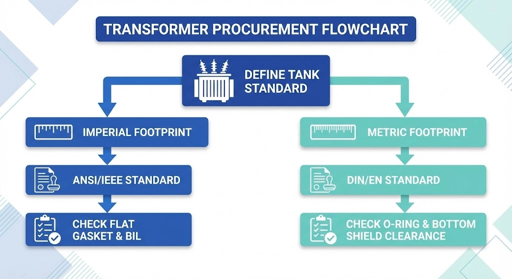
Procuring the correct high-voltage interface component requires more than passing a generic voltage rating from engineering to purchasing. Failing to specify the standard framework—ANSI vs DIN—is the single largest cause of factory clarification delays, extending the RFQ cycle by weeks and introducing fatal compatibility risks. To prevent these mismatches, procurement professionals must verify the physical and electrical parameters before issuing a request for quotation.
Figure 03:A strategic specification workflow ensuring procurement teams select the correct bushing standard before issuing a Request for Quotation.
Core Parameters to Verify
Before issuing an RFQ, ensure the engineering data package explicitly defines the following:
Is the transformer tank designed for an ANSI (imperial) or DIN (metric) flange footprint? Specify the required bolt circle diameter (e.g., 160 mm or 6.25 inches) and the number of mounting holes (e.g., 4-hole or 6-hole).
Provide the nominal system voltage (e.g., 15 kV or 17.5 kV) and the required Basic Impulse Level (BIL). A 15 kV system may require a 95 kV BIL under ANSI or a 75 kV BIL under specific IEC guidelines.
Define the continuous current rating (e.g., 630 A or 1250 A) and the acceptable temperature rise under full load conditions.
Identify whether the tank requires a flat gasket surface or a grooved flange designed for an O-ring (common in DIN bushing well & inserts).
Specify the required creepage distance (e.g., 25 mm/kV or 31 mm/kV) based on the installation site’s altitude and pollution severity.
How to Structure Your RFQ
Stop guessing at specifications and inheriting generic project requirements. ZeeyiElec provides comprehensive technical support to match your specific transformer design with the correct standard. Send your engineering drawings or technical data sheets to our team for a fast, accurate technical review, and eliminate procurement delays before they start.
Global Supply Chain and Lead Time Impacts
The specification of standard frameworks heavily dictates the procurement timeline and landed cost of transformer components. While a design engineer might select a bushing solely based on its dielectric properties or footprint, the purchasing department must grapple with the realities of global manufacturing distribution. Attempting to source a standard that is not native to the project’s installation region reliably disrupts supply chains and inflates project budgets.
Regional Market Dominance
The global distribution equipment market is distinctly fractured. ANSI/IEEE standards dominate North America, portions of Central and South America, and specific regions with historical US grid influence, such as the Philippines. Conversely, DIN/IEC standards are the established baseline across Europe, the Middle East, Africa, and the majority of Asia.
For procurement teams, this geographic dominance translates directly into availability. In their native regions, standard distribution components like a 24 kV / 250 A DIN bushing or a 15 kV ANSI draw-lead bushing are treated as commodity stock, often carrying lead times of just 4 to 6 weeks. However, specifying an ANSI component for a European-built transformer, or vice versa, strips away this localized inventory advantage. Cross-regional sourcing typically extends lead times to 10 to 14 weeks, exposing the project to international shipping delays and customs bottlenecks.
Project Economics and Sourcing Strategies
When buyers force a standard mismatch, unit economics suffer. Manufacturers optimize their tooling, porcelain extrusion, and epoxy casting processes for their primary regional market. Requesting non-native components often triggers custom production runs instead of drawing from existing inventory.
This shift from high-volume production to custom manufacturing frequently results in minimum order quantity (MOQ) requirements of ≥ 50 units and introduces a 20% to 35% cost premium per item. To maintain procurement efficiency, EPC contractors must align their entire bill of materials with the destination region’s dominant standard. This alignment should extend beyond transformer interfaces to include all associated network hardware, ensuring that both the transformer hardware and the connected cable accessories adhere to a unified, locally supportable engineering framework. Sourcing native standards ensures access to local replacement parts for the 30-year expected lifespan of the grid asset.
Frequently Asked Questions
Can I use a DIN bushing on an ANSI-designed transformer tank?
While theoretically possible using custom adapter plates to match the 4-hole or 6-hole bolt circles, field retrofits often face internal clearance conflicts. Engineers must verify that the DIN lower shield does not violate the transformer’s minimum 140 mm striking distance to the core or tank wall before attempting installation.
Are ANSI and DIN voltage classes directly equivalent?
Voltage classes align closely—such as ANSI 15 kV and DIN 12 kV or 17.5 kV—but impulse withstand (BIL) and continuous current testing protocols differ significantly between IEEE and IEC standards. Buyers must specify the exact required BIL, such as 95 kV, rather than assuming a nominal voltage match guarantees transient protection compliance.
What is the standard creepage distance for DIN vs ANSI bushings?
Both standards calculate creepage based on system voltage and pollution severity, typically ranging from 16 mm/kV for light pollution up to 31 mm/kV for very heavy industrial pollution. However, ANSI standard shed profiles often feature alternating diameters to break water cascades, while older DIN designs use uniform sheds, impacting how each performs in heavy coastal contamination zones.
Do DIN bushings use different gasket materials than ANSI bushings?
The base gasket materials, such as nitrile rubber or cork-neoprene, are often identical, but the flange groove designs and required compression ratios differ drastically. Using an ANSI-dimensioned flat gasket on a DIN-grooved flange requiring an 8 mm O-ring will typically result in oil leaks under normal 65°C thermal cycling and pressure variations.
Which bushing standard is more cost-effective for international projects?
Cost depends entirely on the installation region and the original equipment manufacturer’s supply chain, with DIN dominating European and Middle Eastern markets, and ANSI prevalent in the Americas. Selecting the non-native standard for a specific region usually increases lead times by 4 to 8 weeks and raises unit costs by 20% to 35% due to lower regional stocking levels.
How do bottom connections differ between ANSI and DIN standards?
ANSI designs frequently utilize a draw-lead mechanism where a flexible cable is pulled up through the hollow porcelain and secured at the top terminal, ideal for quick field replacements. DIN standards generally employ a solid central copper or brass conductor stem that requires technicians to make rigid bolted connections directly inside the oil-filled transformer tank.
yoyo shi
Yoyo Shi writes for ZeeyiElec, focusing on medium-voltage accessories, transformer components, and cable accessory solutions. Her articles cover product applications, technical basics, and sourcing insights for global electrical industry buyers.