Cable Accessories Series

Heat Shrink Cable Accessories

Complete heat shrink cable termination, joint, tubing, and busbar protection solutions for medium-voltage distribution projects.

ZeeyiElec provides a structured product matrix covering 10kV and 20(24)kV heat shrink cable termination series, plus 1kV/10kV/20(24)kV/35kV joint families and LV insulation tubing options to support project-based technical selection and RFQ delivery.

10kV & 20(24)kV Termination Series Up to 800 mm² Conductor Range OEM/ODM & Export Documentation
Voltage Class 1kV · 10kV · 20(24)kV · 35kV
Configuration Single-Core / Three-Core · Indoor / Outdoor
Application Distribution Cables · Switchgear · Industrial Networks
Product Definition

What Are Heat Shrink Cable Accessories?

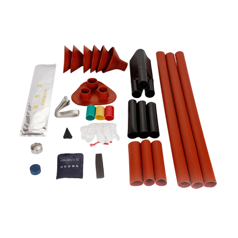
Heat shrink cable accessories are polymer-based insulation and sealing components that recover when heated to form a tight fit around cable interfaces. In medium-voltage systems, a complete heat shrink cable accessory kit typically includes heat shrink cable terminations, heat shrink cable joints, and project-specific tubing or busbar protection parts to ensure dielectric performance, environmental sealing, and long-term connection reliability.

  • 1
    Electrical Insulation — rebuilds insulation structure and electric-field control at cable ends and joint areas.
  • 2
    Sealing & Protection — improves moisture resistance, anti-pollution performance, and mechanical protection for outdoor/industrial operation.
  • 3
    System Matching — supports voltage class, core configuration, and conductor-section-based selection logic for project RFQ.
ZeeyiElec provides a structured matrix covering 10kV and 20(24)kV termination series, plus joint/tubing/busbar families for integrated cable accessory delivery.
System Interface Cable / Switchgear Connection Point
Termination Layer Heat Shrink Cable Termination
This Series Heat Shrink Cable Accessories
Joint & Protection Layer Joint Kits / Tubing / Busbar Sleeves
Product Matrix · SEC-03

Heat Shrink Cable Accessories Product Matrix

Model Selection & Coding Rules

IdentifierNSY / WSY — Indoor / Outdoor Termination
Voltage10 / 20 — 10kV / 20(24)kV Voltage class
Cores/1 / /3 — Single-core / Three-core structure
Tiers (.x).1 to .4 — Standard conductor-section ranges
AccessoriesJNT (Joints), TUB (Tubing), BUS (Busbar Accessories)
Selection Flow: Voltage Class → Indoor/Outdoor → Core Type → Section Tier → Project Confirmation
Heat Shrink Accessories Collection Full Family Reference

Heat Shrink Cable Terminations (NSY/WSY Series)

10kV Single-Core Indoor (NSY-10/1.x)

NSY-10/1.1 25–50 mm²
NSY-10/1.2 70–120 mm²
NSY-10/1.3 150–240 mm²
NSY-10/1.4 300–500 mm²

10kV Single-Core Outdoor (WSY-10/1.x)

WSY-10/1.1 25–50 mm²
WSY-10/1.2 70–120 mm²
WSY-10/1.3 150–240 mm²
WSY-10/1.4 300–500 mm²

10kV Three-Core Indoor (NSY-10/3.x)

NSY-10/3.1 25–50 mm²
NSY-10/3.2 70–120 mm²
NSY-10/3.3 150–240 mm²
NSY-10/3.4 300–500 mm²

10kV Three-Core Outdoor (WSY-10/3.x)

WSY-10/3.1 25–50 mm²
WSY-10/3.2 70–120 mm²
WSY-10/3.3 150–240 mm²
WSY-10/3.4 300–500 mm²

20kV Single-Core Indoor (NSY-20/1.x)

NSY-20/1.1 50–95 mm²
NSY-20/1.2 120–240 mm²
NSY-20/1.3 300–400 mm²
NSY-20/1.4 500–800 mm²

20kV Single-Core Outdoor (WSY-20/1.x)

WSY-20/1.1 50–95 mm²
WSY-20/1.2 120–240 mm²
WSY-20/1.3 300–400 mm²
WSY-20/1.4 500–800 mm²

20kV Three-Core Indoor (NSY-20/3.x)

NSY-20/3.1 50–95 mm²
NSY-20/3.2 120–240 mm²
NSY-20/3.3 300–400 mm²
NSY-20/3.4 500–800 mm²

20kV Three-Core Outdoor (WSY-20/3.x)

WSY-20/3.1 50–95 mm²
WSY-20/3.2 120–240 mm²
WSY-20/3.3 300–400 mm²
WSY-20/3.4 500–800 mm²

Heat Shrink Cable Intermediate Joints

Product FamilyVoltage ClassCore TypeTypical ApplicationRFQ Required Inputs
1kV Joint Kit1kV1/2/3/4/5 CoreLV cable extension/repairConductor section, insulation type, environment
10kV Joint Kit10kV1/3 CoreMV distribution continuityCable structure, shield type, route condition
20(24)kV Joint Kit20(24)kV1/3 CoreUtility/Industrial feeder projectsConductor section, sheath/shield, installation mode
35kV Joint Kit35kV1/3 CoreHigh-voltage feeder connectionsFull cable construction + project drawings

1kV Low-Voltage Heat Shrink Tubing

Diameter (Φ) RangeGroupPackaging LengthUnit
1.0 / 1.5 / 2.0 / 2.5 / 3.0 / 3.5 / 4.0Group A200 mRoll
5.0 / 6.0 / 8.0 / 10 / 12 / 14 / 15 / 16 / 18 / 20 / 22Group B100 mRoll
25 / 28 / 30 / 35 / 40 / 50 / 60 / 70 / 80 / 90 / 100 / 120 / 150Group C25 mRoll
* Note: Available in standard colors (Black/Red/Blue) and Yellow-Green stripes.

Busbar & Junction Box Accessories

FamilyFunctionSelection BasisRFQ Inputs
Busbar Sleeves / TubesInsulation and touch protectionBusbar width/thickness + voltageBar drawing + Quantity (m)
Wrapping / Taping SetJoint insulation reinforcementGeometry + insulation targetSite layout + environment
Junction Box SetConnection point protectionInterface type + constraintsCabinet drawing + BOM target
Engineering Summary: Termination tiers cover up to 800mm² based on standard cross-linked polyolefin technical sheets. Joints and busbar accessories are project-configured based on RFQ inputs.
Engineering Specifications · SEC-04

Technical Specifications for Heat Shrink Cable Accessories

This section summarizes the practical engineering parameters used to select heat shrink cable accessories, including termination model ranges, voltage classes, core configurations, joint families, and tubing dimensions for low-voltage insulation tasks.

Voltage Classes

1kV / 10kV / 20(24)kV / 35kV

Across tubing, joints, and MV termination families

Termination Section Range

25–800 mm²

Tiered by .1 to .4 model coding

Core Configuration

Single-Core / Three-Core

Mapped as /1 and /3 in NSY/WSY series

Tubing Diameter Coverage

Φ1.0–Φ150

200m / 100m / 25m packaging groups

Selection Logic for Heat Shrink Cable Termination

  • Step 1: Confirm voltage class (10kV or 20(24)kV) for the target feeder/circuit.
  • Step 2: Choose installation condition as NSY (Indoor) or WSY (Outdoor).
  • Step 3: Select core structure /1 (single-core) or /3 (three-core).
  • Step 4: Match conductor section by tier .1 to .4 (from 25 mm² up to 800 mm², depending on voltage class).
  • Step 5: Confirm accessories and project BOM for final RFQ alignment.
Engineering note: For mixed projects (indoor GIS room + outdoor termination point), indoor and outdoor termination kits are typically specified separately in one BOM.

Family Scope in This Series Page

  • Heat shrink cable terminations: 10kV and 20(24)kV, NSY/WSY, /1 and /3 formats.
  • Heat shrink cable joints: 1kV, 10kV, 20(24)kV, and 35kV families.
  • Heat shrink tubing: LV insulation tubing from Φ1.0 to Φ150.
  • Busbar-related accessories: sleeve, wrapping/taping, and junction-point protection sets.
Joint and busbar-related items are commonly configured by project environment and cable construction; final model mapping is confirmed during RFQ technical review.

Termination Model Matrix (Engineering Summary)

Voltage ClassCore TypeIndoor SeriesOutdoor SeriesSection RangeTier Rule
10kVSingle-CoreNSY-10/1.xWSY-10/1.x25–500 mm².1 / .2 / .3 / .4
10kVThree-CoreNSY-10/3.xWSY-10/3.x25–500 mm².1 / .2 / .3 / .4
20(24)kVSingle-CoreNSY-20/1.xWSY-20/1.x50–800 mm².1 / .2 / .3 / .4
20(24)kVThree-CoreNSY-20/3.xWSY-20/3.x50–800 mm².1 / .2 / .3 / .4

Joint, Tubing, and Busbar Family Parameters

FamilyVoltage ScopeConfiguration BasisTypical Engineering Inputs
Heat Shrink Cable Joint1kV / 10kV / 20(24)kV / 35kVCable structure + core typeConductor section, shielding structure, route/environment
LV Heat Shrink Tubing1kVDiameter + packaging groupΦ size (1.0–150), roll length (200m / 100m / 25m)
Busbar Sleeve / Wrapping / Junction SetProject-specificGeometry + insulation targetBusbar width/thickness, interface layout, cabinet constraints
Material System: Cross-linked polyolefin heat shrink family for insulation and sealing applications.
BOM Method: Termination models can be selected by coding rule; joint and busbar items are validated by RFQ details.
Documentation Support: Model confirmation, section matching, and project compatibility review before quotation.
Project Capability

Engineering-Focused Heat Shrink Cable Accessory Supply

From model coding confirmation to project BOM matching, ZeeyiElec supports medium-voltage cable accessory procurement with structured technical review, configuration alignment, and export-ready delivery documentation.

Model Coding Verification

Validate NSY/WSY coding logic by voltage class, core type, and conductor range before order confirmation.

Project BOM Matching

Combine terminations, joint kits, tubing, and busbar accessories into one coordinated package for installation consistency.

Application-Based Selection

Recommend indoor/outdoor and single-core/three-core configurations based on cable structure and site conditions.

Export Documentation Support

Provide standard commercial and shipping documents aligned with international B2B procurement workflow.

Application Scenarios

Where Heat Shrink Cable Accessories Are Applied

This heat shrink cable accessories series supports typical medium-voltage distribution and industrial cable interfaces. Selection is mapped by installation environment, voltage class, cable structure, and required protection level.

Scenario 01

Utility & Substation Distribution Feeders

Used for cable termination and intermediate connection in 10kV/20(24)kV distribution lines where long-term insulation stability and moisture sealing are required.

Recommended Family NSY/WSY Heat Shrink Cable Termination + MV Joint Kits
Typical Voltage 10kV / 20(24)kV
Scenario 02

Industrial Plants & Process Facilities

Applied in plant cable routes with dense equipment interfaces, supporting both maintenance retrofits and new installation where installation consistency is critical.

Recommended Family Termination Kits + 1kV/10kV/24kV Joint Solutions + Tubing
Typical Structure Single-Core / Three-Core
Scenario 03

Switchgear & Cabinet Busbar Interfaces

Used for busbar insulation reinforcement and connection-point protection inside switchgear/cabinet systems, improving touch safety and local insulation robustness.

Recommended Family Busbar Sleeves + Wrapping / Taping + Junction Box Set
Selection Basis Busbar width/thickness + interface geometry

Application-to-Product Mapping (Engineering Quick View)

Application NeedPrimary Product FamilyKey Input ParametersOutput Goal
Cable end connection in MV networkHeat Shrink Cable Termination (NSY/WSY)Voltage class, indoor/outdoor, core type, conductor sectionStable insulation interface and reliable sealing
Cable route extension / repairHeat Shrink Cable Joint KitsCable construction, shield type, section range, installation modeContinuity restoration and dielectric integrity
General LV insulation reinforcement1kV Heat Shrink TubingRequired final diameter, bundle size, packaging preferenceMechanical protection and identification support
Busbar / cabinet interface protectionBusbar Sleeves & Junction AccessoriesBusbar dimensions, interface layout, clearance constraintsImproved touch safety and insulation robustness

Engineering note: for faster model confirmation, submit cable voltage level, conductor section range, core configuration, insulation/shield structure, and installation environment together in one RFQ package.

Selection Guide

How to Select Heat Shrink Cable Accessories for Medium Voltage Projects

Use this structured guide to choose the right heat shrink cable accessories combination by voltage class, installation condition, cable configuration, and conductor section range—then confirm final BOM with project details.

01

Confirm Voltage Class

Start with project voltage level: 10kV or 20(24)kV for termination families; joint projects may extend to higher classes by RFQ.

02

Define Installation Environment

Select indoor vs outdoor operation and clarify humidity/pollution exposure to determine appropriate sealing and accessory structure.

03

Check Cable Configuration

Identify single-core or three-core cable type, insulation/shield design, and whether the need is termination, joint, tubing, or busbar protection.

04

Match Conductor Section

Use section tier (.1~.4) to map model coding range, such as 25–50, 70–120, 150–240, 300–500/800 mm² depending on series.

05

Finalize RFQ Inputs

Submit voltage, cable construction, section range, application location, and required family list for engineering confirmation and BOM output.

Heat Shrink Cable Accessories Selection Matrix

Selection ConditionTypical ChoiceMapped Product FamilyModel / Range ReferenceNotes
Termination 10kV + Single-Core + IndoorEnd connection insulation build-upNSY termination kitNSY-10/1.x (25–500 mm²)Choose .1/.2/.3/.4 by conductor section
Termination 10kV + Three-Core + OutdoorOutdoor weather-exposed cable endWSY termination kitWSY-10/3.x (25–500 mm²)Confirm installation accessories in BOM
Termination 20(24)kV + Single/Three-CoreMV distribution interfaceNSY/WSY 20-seriesNSY/WSY-20/x.x (50–800 mm²)Verify section band and site condition
Joint Cable extension or repairIntermediate insulation restorationHeat shrink joint kits1kV / 10kV / 20(24)kV / 35kVNeed cable insulation/shield details
Tubing LV harness / insulation reinforcementGeneral insulation + identification1kV heat shrink tubingΦ1.0 to Φ150, multi-pack lengthsPick size by final recovered diameter
Busbar Switchgear/cabinet protectionTouch-safe insulation coveringBusbar sleeves / wrapping / junction accessoriesProject-configuredBased on busbar width, thickness, geometry

Common Selection Mistakes to Avoid

  • Choosing only by voltage class without checking conductor section range.
  • Ignoring single-core vs three-core differences in kit structure.
  • Omitting cable insulation/shield structure for joint kit selection.
  • Using tubing diameter without considering recovered-fit requirement.

Minimum RFQ Information for Fast Confirmation

  • Project voltage class and application location (indoor/outdoor).
  • Cable core type, conductor section range, and cable construction.
  • Required product families: termination / joint / tubing / busbar.
  • Target quantity and preferred delivery window.

This guide is intended for engineering pre-selection. Final model confirmation should be completed against project drawings and detailed cable specifications.

Quality & Documentation

Quality Control and Export Documentation for Heat Shrink Cable Accessories

Every heat shrink cable accessories order is controlled through a standard inspection workflow and matched documentation package, supporting technical review, project approval, and export delivery coordination.

Quality Control Workflow

01

Raw Material Verification

Incoming batch verification for base polymer and key components against internal technical requirements before production release.

02

In-Process Dimensional Check

Dimensional and visual checks during production to maintain fit consistency across termination, joint, tubing, and busbar accessory families.

03

Finished Product Inspection

Final batch review for appearance, size range conformance, marking/packing consistency, and accessory completeness by BOM.

04

Packing & Shipment Validation

Pre-shipment verification of label, carton list, quantity alignment, and export packing integrity for international logistics handling.

Inspection Focus by Product Family

  • T
    Termination Kits Model-coding accuracy (NSY/WSY), section range matching, and full accessory completeness by kit list.
  • J
    Joint Kits Configuration consistency with cable structure inputs and project BOM requirement.
  • U
    Insulation Tubing Diameter range consistency, packaging-length confirmation, and identification labeling.
  • B
    Busbar Accessories Geometry compatibility with busbar dimensions and cabinet interface constraints.

Documentation Package (Project / Export Support)

Document TypePurposeWhen ProvidedTypical Use
Technical Product Specification SheetDefines model family, section range, and configuration basisQuotation / technical evaluation stageEngineering review and model confirmation
Commercial PI / Commercial InvoiceCommercial terms and order-value referenceOrder confirmation and shipment stageProcurement and finance processing
Logistics Packing ListDetails carton quantity, item mapping, and shipment countPre-shipment / shipment releaseWarehouse receiving and customs checking
Quality Inspection / Conformance RecordSummarizes finished-batch inspection statusPer agreed order arrangementProject QA filing and delivery approval
Origin Certificate SupportSupports destination-country import processWhen requested by customer/marketCustoms clearance support

Document scope can be aligned to project and destination requirements before shipment. For special market-entry files, confirm required templates at RFQ stage.

FAQ & Resources

Heat Shrink Cable Termination FAQ & Technical Resources

Practical answers for heat shrink cable terminations, joints, and tubing selection—focused on installation workflow, tooling boundaries, and sizing logic for field applications.

Related Resources

The standard method is: prepare cable and insulation layers → install stress-control/insulation components in sequence → position termination accessories → apply uniform heat to recover each tube from center outward → complete sealing and final inspection.
Typical steps include cable stripping by drawing dimensions, conductor preparation, lug/crimp completion (if required), sequential component placement, controlled heating, and post-install checks for position, recovery uniformity, and sealing completeness.
If the connector design is crimp-based, crimping is required before shrinking. Heat shrink provides insulation/sealing; it does not replace the mechanical and electrical joint function of the connector interface itself.
First complete the conductor connection (crimp or approved joint), then center tubing over the joint and heat evenly with controlled distance/temperature until full recovery. Avoid local overheating and keep movement minimal during cooling.
Choose tubing by matching pre-shrink inner diameter to fit-over requirements and post-shrink diameter to sealing target. Final selection depends on joint geometry, insulation thickness, and required sealing margin rather than one fixed ratio.
For consistent quality, a controlled heat gun is recommended. Open flame or contact heating can cause uneven recovery, scorching, or local damage, especially in medium-voltage accessory installations.
In most technical applications, no. Hair dryers usually cannot provide stable temperature and focused airflow needed for uniform recovery, particularly for thicker-wall components and structured cable accessory kits.
Common issues are uneven shrinking, trapped air, component misplacement, insufficient sealing, and overheating damage. Most are prevented through accurate stripping dimensions, correct sequence, and controlled progressive heating.
Project practice typically includes straight-through joints and branch/repair scenarios, with configuration differences by voltage class and core structure. Final kit composition is selected against cable construction and site conditions.
It should be uniformly recovered and closely conform to the substrate with no gaps, wrinkles, or burn marks. Acceptance is based on complete coverage, sealing integrity, and stable interface geometry after cooling.