Transformer Accessories Series

Loadbreak Switches for Pad-Mounted Distribution Transformers

Engineered for reliable switching in oil-immersed transformer systems. ZeeyiElec loadbreak switch portfolio covers Two-Position and Four-Position Sectionalizing designs with hook-stick operation, stored-energy quick action, and model options for 1-phase and 3-phase applications.

Two-Position & Four-Position Options Hook-Stick Operable Mechanism Export Engineering Support
Voltage Class 15/25 kV & 38/40.5 kV
Current Rating 630 A
Application Scope 1-Phase / 3-Phase, Oil-Filled Transformers
Product Definition

What Is a Loadbreak Switch in a Transformer System?

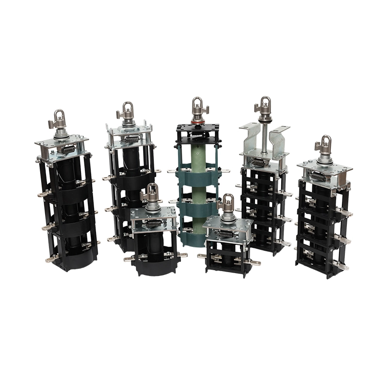
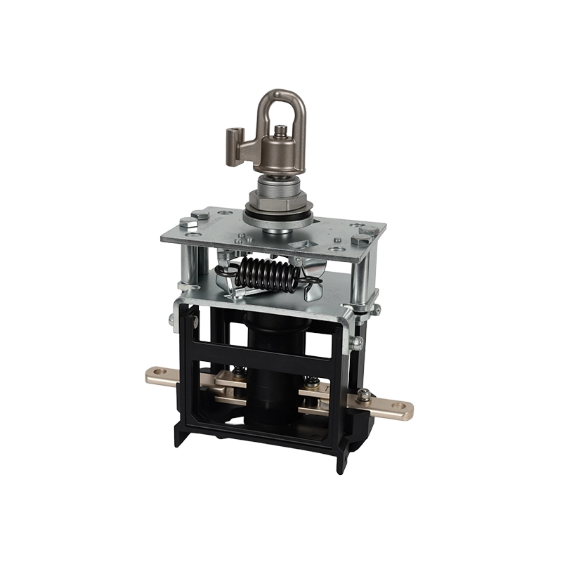
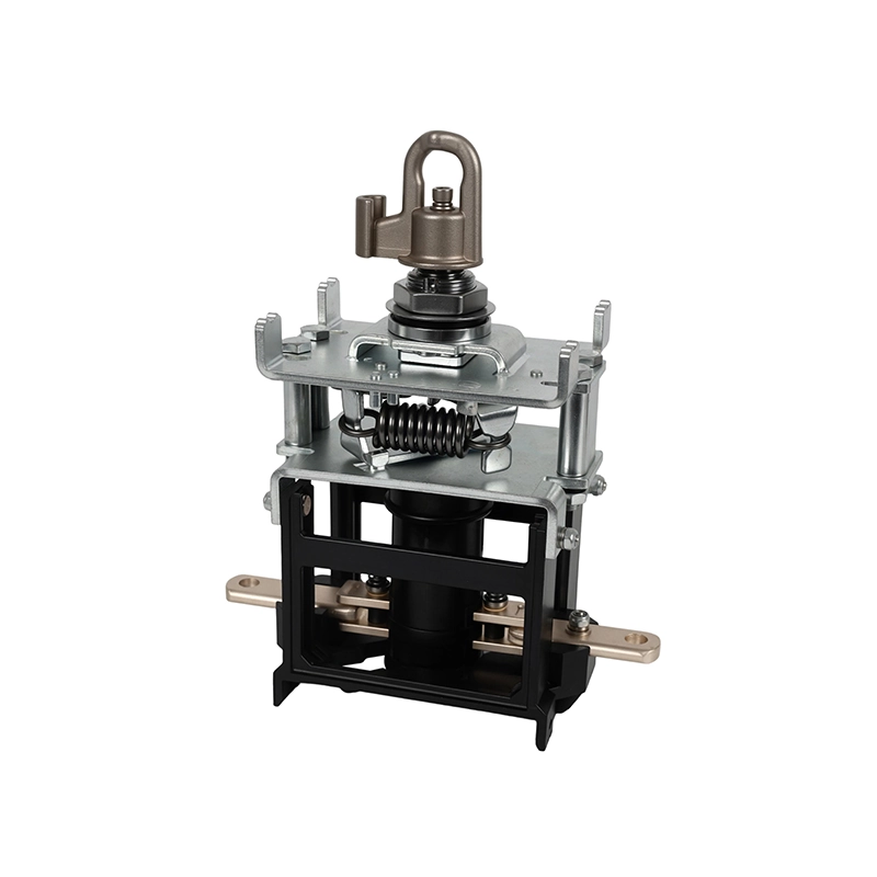
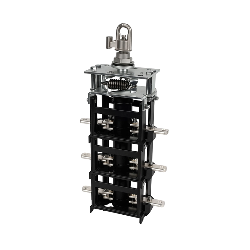
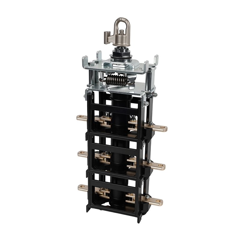
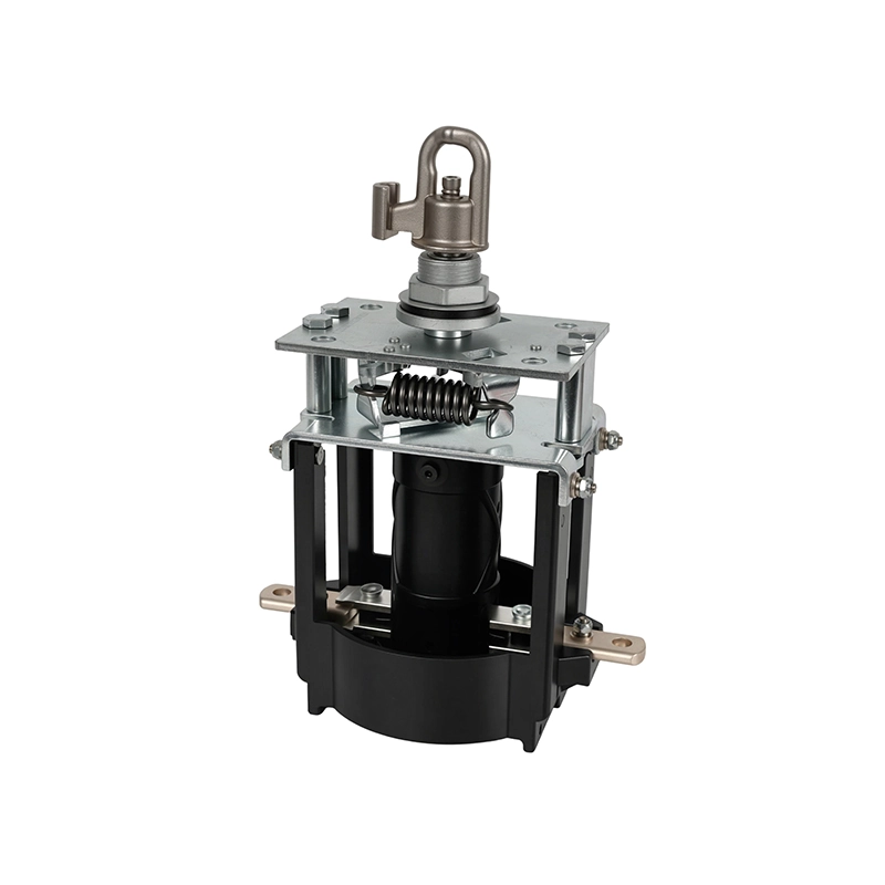
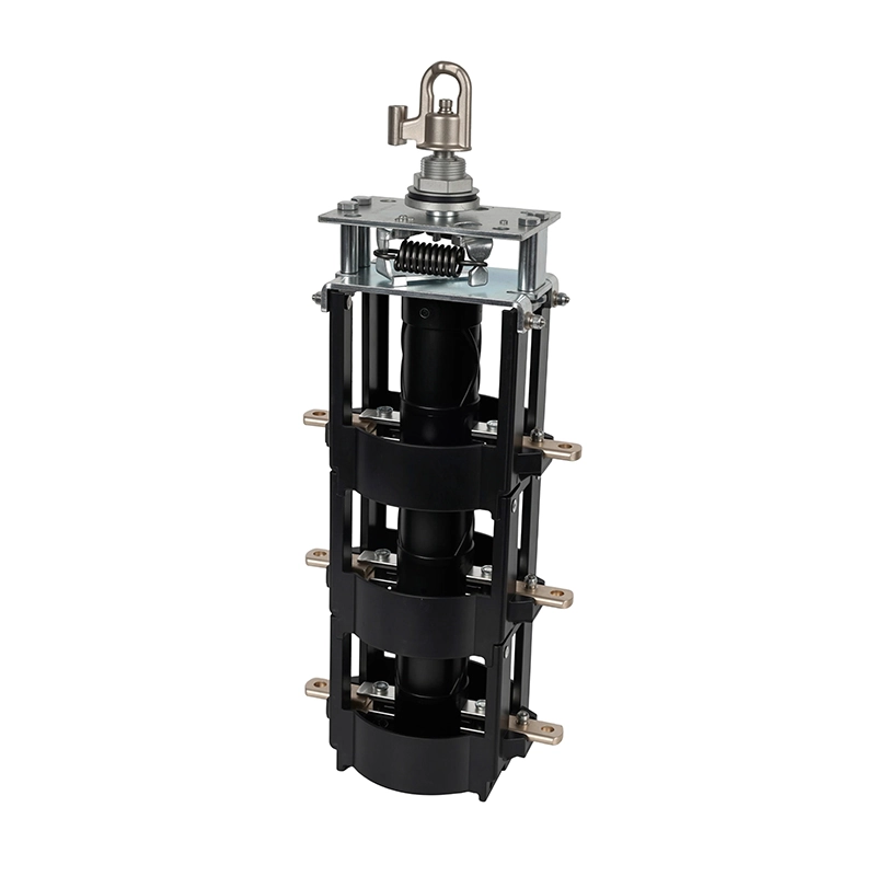
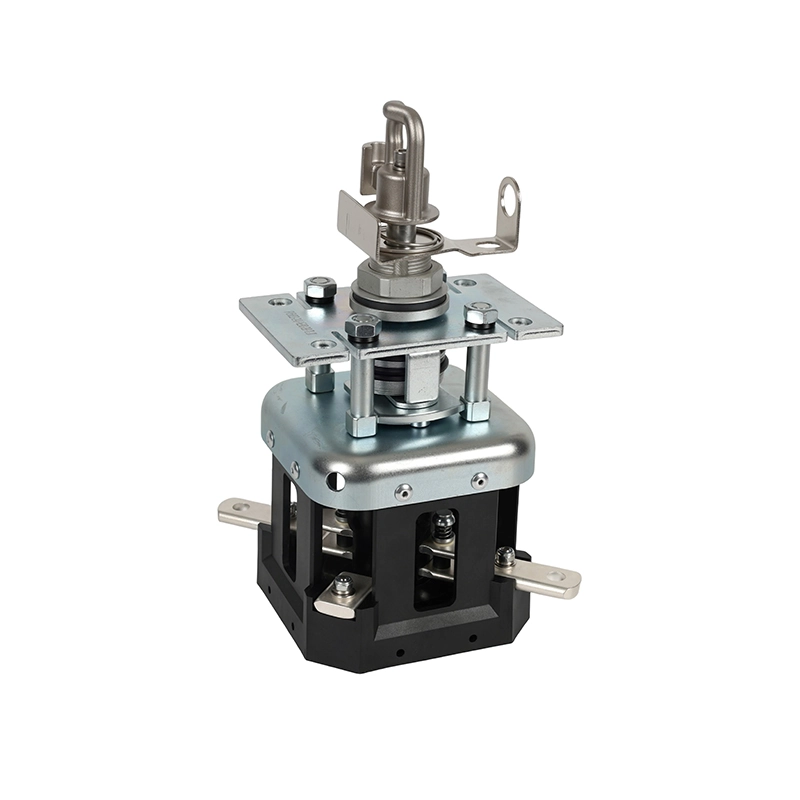
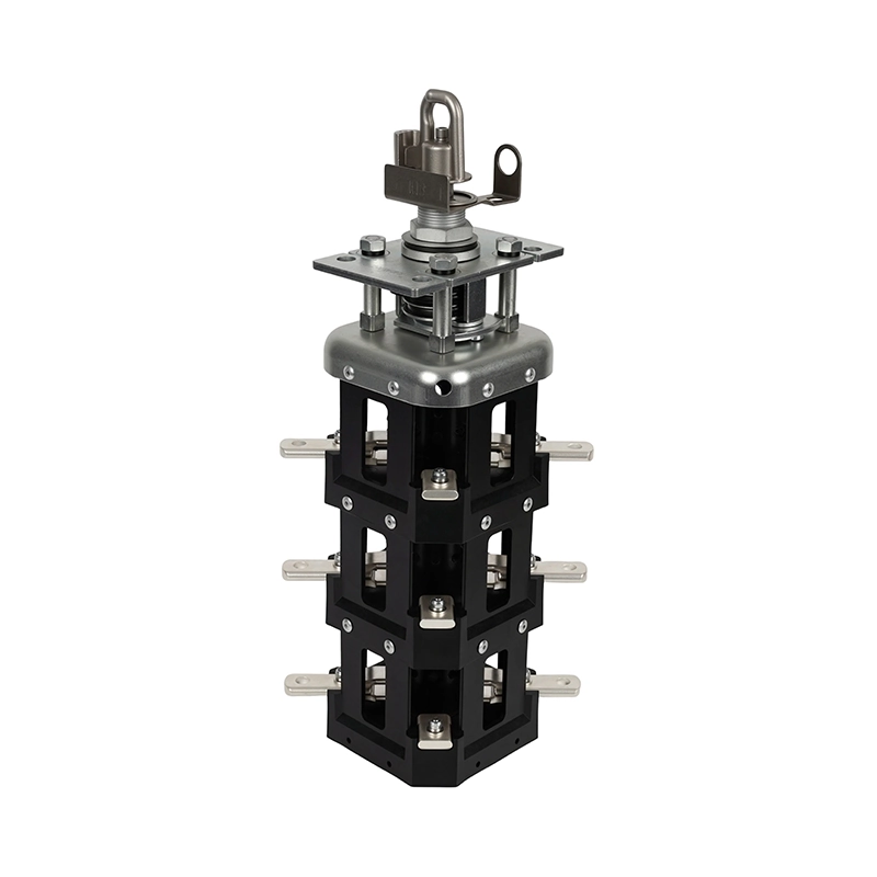
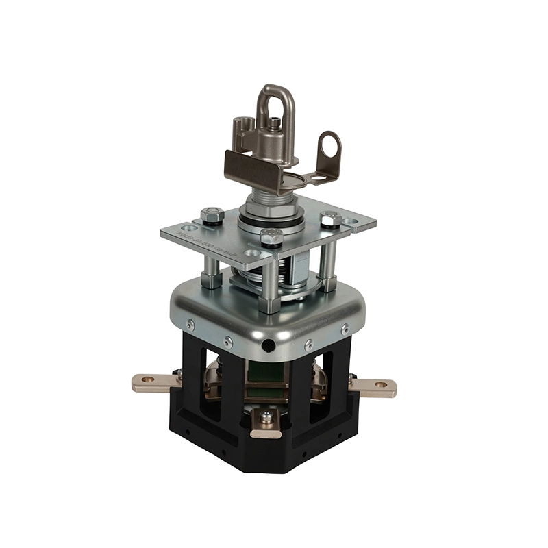
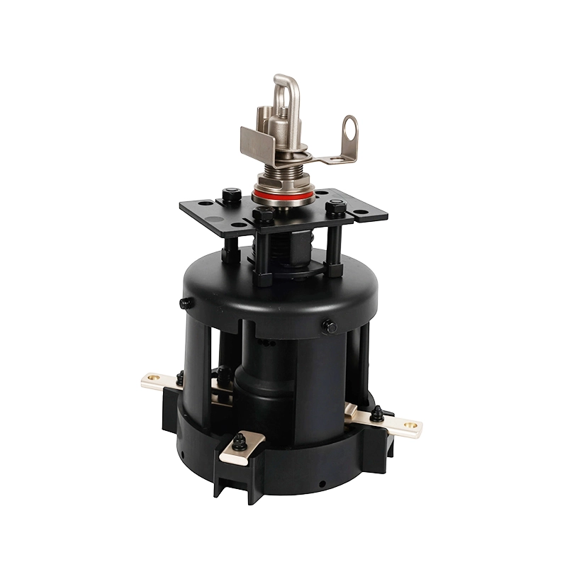
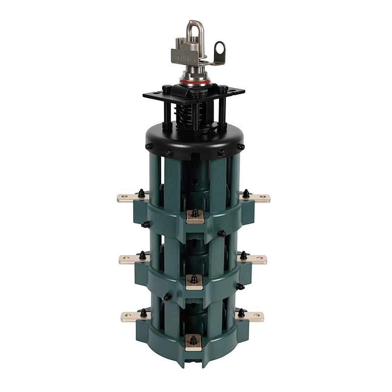
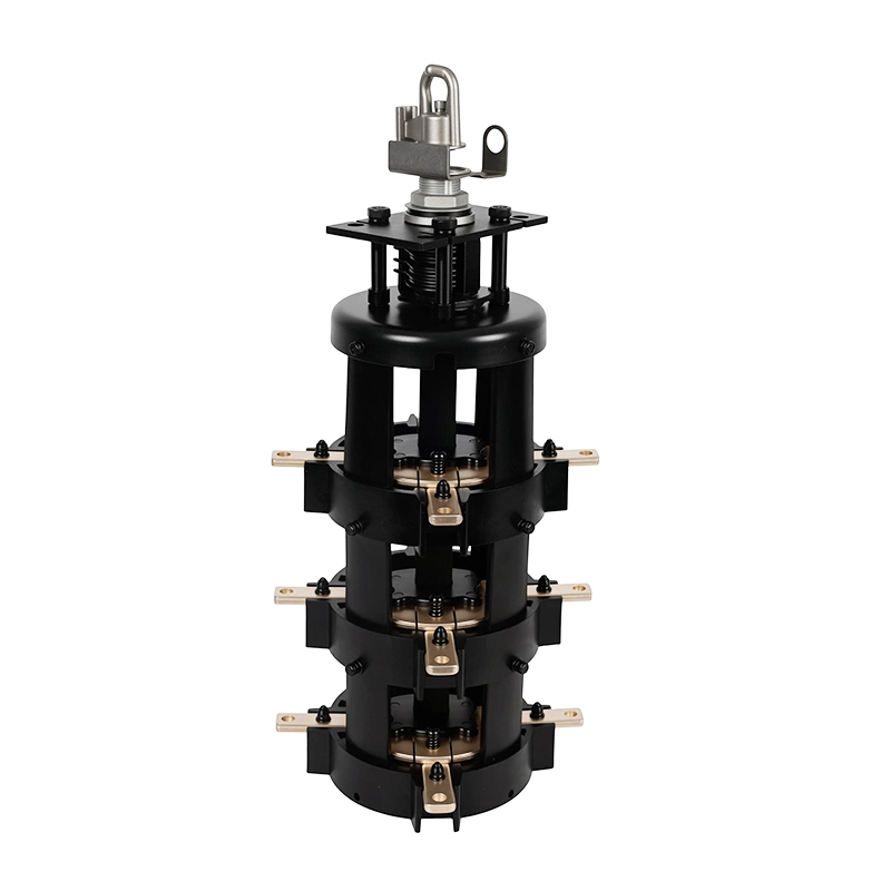
A loadbreak switch is a transformer-mounted switching device used to make or break rated current in oil-immersed distribution equipment. In pad-mounted applications, the switch provides a reliable interface for feeder isolation, circuit transfer, and sectionalizing logic. ZeeyiElec covers both two-position loadbreak switch and four-position sectionalizing loadbreak switch configurations for utility and industrial transformer systems.

  • 1
    Quick Loadmake/Loadbreak Action — stored-energy mechanism enables consistent switching independent of operator speed.
  • 2
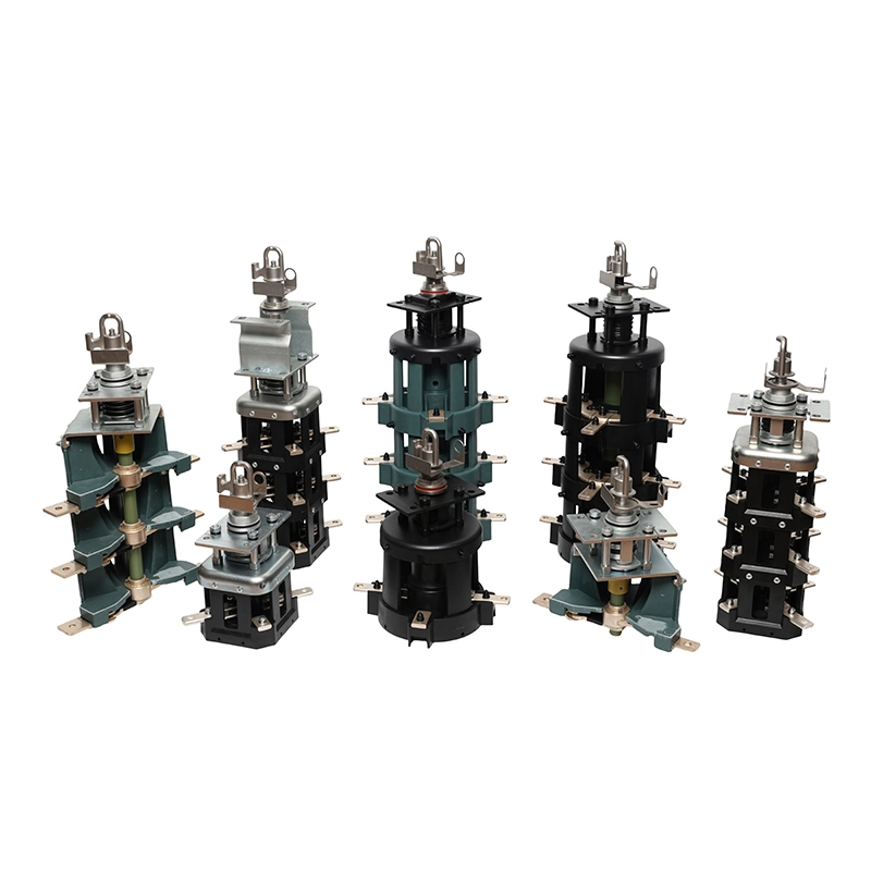
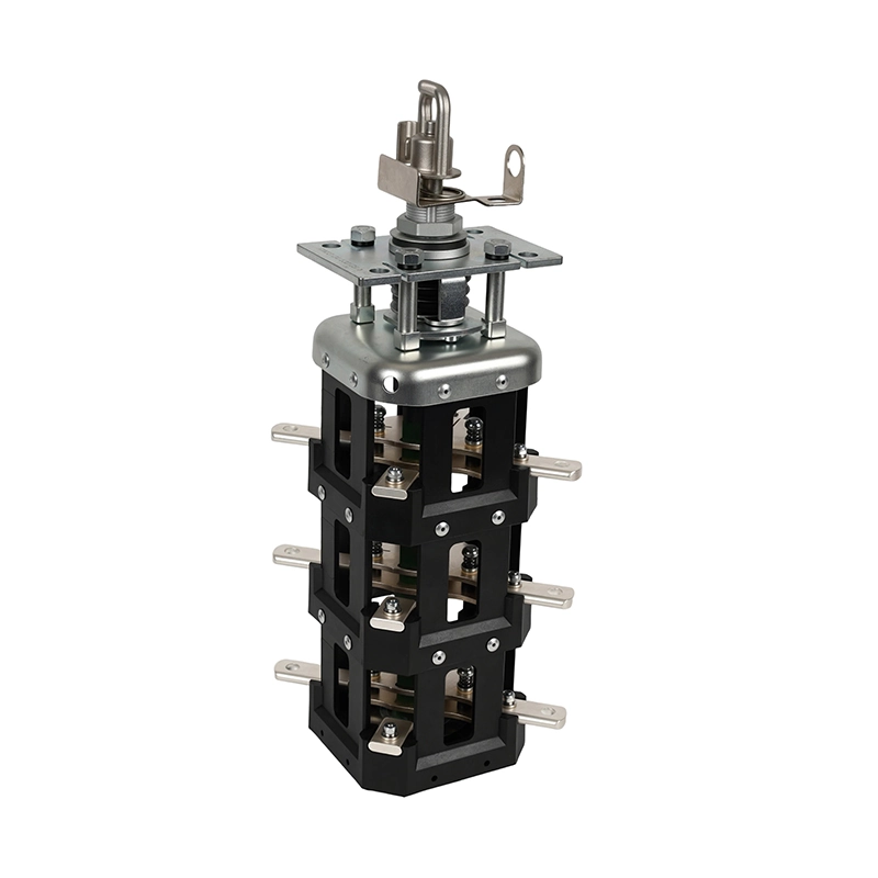
    Series Logic Coverage — choose two-position for standard switching, or four-position for sectionalizing and transfer paths.
  • 3
    Transformer Compatibility — designed for pad-mounted, oil-filled transformer structures with export-oriented model options.
Continue to SEC3 for model families and SEC4 for ratings/specifications, dimensions, and ordering references.
Application Layer Pad-Mounted Oil-Immersed Transformer
This Product Loadbreak Switch
Series A Two-Position
Loadbreak Switch
Series B Four-Position Sectionalizing
Loadbreak Switch
Product Families

Loadbreak Switch Model Matrix

Select your required configuration series below. Our engineering matrix is categorized by operating logic (Two-Position vs Four-Position) to streamline your specification process.

Two-Position Loadbreak Switches Series I
Voltage: 15-40.5 kV Current: 630 A Mech Life: 2,000 Ops Logic: ON/OFF
Overview Series Overview

Series I Overview

Volt15-40.5kV
Phase1 & 3
Amps630 A
TypeStandard

Hook-stick operable, spring-assisted quick make/break performance.

Request Spec
1-Phase FYB-(15)25/630-25-J1

FYB-(15)25/630-25-J1

Volt15/25 kV
ConfCompact
Amps630 A
TypeStandard

Single-phase configuration for compact transformer layouts.

Request Spec
1-Phase FYB-(15)25/630-25-J1-L

FYB-(15)25/630-25-J1-L

Volt15/25 kV
ConfAlt-Link
Amps630 A
TypeStandard

Single-phase variant with alternate mechanical linkage.

Request Spec
3-Phase FYB-(15)25/630-25

FYB-(15)25/630-25

Volt15/25 kV
ConfMainstream
Amps630 A
TypeStandard

Mainstream model for pad-mounted distribution transformers.

Request Spec
3-Phase FYB-(15)25/630-25-L

FYB-(15)25/630-25-L

Volt15/25 kV
ConfAlt-Link
Amps630 A
TypeStandard

Three-phase version for projects requiring alternate linkage.

Request Spec
1-Phase BYFI-(38)40.5/630-20-J1

BYFI-(38)40.5/630-20-J1

Volt40.5 kV
ConfHigh Volt
Amps630 A
TypeStandard

Higher-voltage class single-phase option for 40.5kV systems.

Request Spec
3-Phase BYFI-(38)40.5/630-20

BYFI-(38)40.5/630-20

Volt40.5 kV
ConfHigh Volt
Amps630 A
TypeStandard

Robust 3-phase high-voltage-class model for heavy duty.

Request Spec
Four-Position Sectionalizing Switches Series II
Voltage: 15-40.5 kV Switching: BBM / MBB Mech Life: 3,000 Ops Logic: Sectionalizing
Overview Series Overview

Series II Overview

Volt15-40.5kV
LogicMulti
Amps630 A
TypeBBM/MBB

Sectionalizing logic with multi-position configuration flexibility.

Request Spec
1-Phase FYN33-J1-BBM

FYN33-(15)25-J1 (BBM)

Volt15/25 kV
LogicBBM
Amps630 A
PhaseSingle

Single-phase BBM configuration for sectionalizing operations.

Request Spec
3-Phase FYN33-BBM

FYN33-(15)25 (BBM)

Volt15/25 kV
LogicBBM
Amps630 A
PhaseThree

Three-phase BBM model for standard sectionalizing logic.

Request Spec
1-Phase FYN33-J1-MBB

FYN33-(15)25-Y-J1 (MBB)

Volt15/25 kV
LogicMBB
Amps630 A
PhaseSingle

Single-phase MBB variant for continuous transfer switching.

Request Spec
3-Phase FYN33-Y-MBB

FYN33-(15)25-Y (MBB)

Volt15/25 kV
LogicMBB
Amps630 A
PhaseThree

Three-phase MBB model for multi-source sectionalizing.

Request Spec
1-Phase FYN33-HV-J1

FYN33-(38)40.5-J1 (BBM)

Volt40.5 kV
LogicBBM
Amps630 A
PhaseSingle

High-voltage single-phase BBM option for advanced applications.

Request Spec
3-Phase FYN33-HV-BBM

FYN33-(38)40.5 (BBM)

Volt40.5 kV
LogicBBM
Amps630 A
PhaseThree

Three-phase BBM model for 40.5kV class sectionalizing.

Request Spec
3-Phase FYN33-HV-MBB

FYN33-(38)40.5-Y (MBB)

Volt40.5 kV
LogicMBB
Amps630 A
PhaseThree

High-voltage MBB configuration for complex feeder logic.

Request Spec
Engineering Specifications

Loadbreak Switch Ratings (Two-Position & Four-Position)

The technical data below provides a comprehensive overview of electrical ratings and model coverage for preliminary selection. For detailed dimensional drawings and internal structure mapping, please refer to the subsequent drawings module.

Electrical Ratings

Parameter15/25 kV Class38/40.5 kV Class
Rated Voltage15/25 kV38/40.5 kV
Rated Frequency60 Hz60 Hz
Rated Current630 A630 A
4s Thermal Withstand Current20 kA25 kA
Dynamic Withstand Current50 kA63 kA
Impulse Withstand Voltage (BIL)125/145 kV200/215 kV
1-Min Power Frequency Withstand55/60 kV95/110 kV
Mechanical Life2,000 operations2,000 operations
Tank Thickness Reference6–8 mm6–8 mm

Model Coverage Snapshot

ModelSeriesVoltage ClassPhaseSwitching Type
FYB-(15)25/630-20-J1Two-Position15/25 kV1-PhaseStandard
FYB-(15)25/630-20-J1-LTwo-Position15/25 kV1-PhaseStandard
FYB-(15)25/630-20Two-Position15/25 kV3-PhaseStandard
FYB-(15)25/630-20-LTwo-Position15/25 kV3-PhaseStandard
BYFI-(38)40.5/630-25-J1Two-Position38/40.5 kV1-PhaseStandard
BYFI-(38)40.5/630-25Two-Position38/40.5 kV3-PhaseStandard

Electrical Ratings

Parameter15/25 kV Class38/40.5 kV Class
Rated Voltage15/25 kV38/40.5 kV
Rated Current630 A630 A
Switching Positions4-Position4-Position
Switching LogicBBM / MBBBBM / MBB
Mechanical Life3,000 operations3,000 operations
Application TypeSectionalizing / TransferSectionalizing / Transfer

* See detailed datasheet for full withstand matrix and short-time current ratings.

Model Coverage Snapshot

ModelSeriesVoltage ClassPhaseSwitching Type
FYN33-(15)25/630-25-J1Four-Position15/25 kV1-PhaseBBM
FYN33-(15)25/630-25Four-Position15/25 kV3-PhaseBBM
FYN33-(15)25/630-25-Y-J1Four-Position15/25 kV1-PhaseMBB
FYN33-(15)25/630-25-YFour-Position15/25 kV3-PhaseMBB
FYN33-(38)40.5/630-25-J1Four-Position38/40.5 kV1-PhaseBBM
FYN33-(38)40.5/630-25Four-Position38/40.5 kV3-PhaseBBM
FYN33-(38)40.5/630-25-YFour-Position38/40.5 kV3-PhaseMBB
Engineering Layout

Dimensions, Structure & Wiring Logic

Installation interface specifications and internal switching topology. Confirm physical clearance and circuit logic prior to final layout.

Two-Position Logic

OFF
Open
ON
Closed

Mechanism: Spring-charged over-toggle.
Speed: Operation independent of operator speed (<1 cycle).
Structure: Single deck (1-Phase) or stacked (3-Phase).

Four-Position Logic T-Blade

Line A
Line B
LOAD
BBM
Source A
Break
Source B
MBB
Source A
A+B
Source B

Physical Installation Interface

Mounting Pattern

4x M10 Holes
Spacing: 110 ±0.5 mm (Square)
Center Hole: Φ20mm

Tank Requirements

Wall Thickness: 6mm - 8mm
Installation: Welded Boss or Gasketed Flange

Operation

Hook-stick operable (Eyelet)
Torque: Minimal input required
Rotation: 360° (4-Pos)

Dimension Reference Guide

Model SeriesTypePhasePDF Ref.Approx. Height (mm)
FYB-(15)25 (J1)2-Pos1-PhaseFig. 4280
FYB-(15)25 (J1-L)2-Pos1-PhaseFig. 5279
FYB-(15)252-Pos3-PhaseFig. 7558
FYB-(15)25 (L)2-Pos3-PhaseFig. 8472
BYFI-(38)40.5 (J1)2-Pos1-PhaseFig. 6316
BYFI-(38)40.52-Pos3-PhaseFig. 9590
FYN33-(15)254-Pos1-PhaseFig. 5585
FYN33-(15)254-Pos3-PhaseFig. 8485
FYN33-(38)40.54-Pos1-PhaseFig. 7334
FYN33-(38)40.54-Pos3-PhaseFig. 9590
Application Guide

Where to Use Two-Position vs Four-Position Loadbreak Switches

Selecting the correct switch series depends heavily on your distribution network topology and operational requirements. This guide matches common application scenarios with our recommended loadbreak switch configurations to simplify your preliminary selection process prior to final engineering review.

Two-Position

Standard Pad-Mounted Distribution Feeder

Network Condition Simple radial feed system ending at a transformer.
Why Only basic on/off isolation is needed for maintenance.
Suggested Setup 15/25kV, 3-Phase, Standard Logic
Four-Position

Utility Sectionalizing Point

Network Condition Loop feed system where the transformer is a node in a ring.
Why Requires ability to feed from Line A, Line B, or isolate sections.
Suggested Setup 15/25kV, 3-Phase, BBM Logic
Two-Position

Industrial Park Branch Distribution

Network Condition Dedicated spur line feeding a single facility transformer.
Why Cost-effective solution where loop switching is handled upstream.
Suggested Setup 15/25kV or 38kV, 3-Phase
Four-Position

Backup Source Transfer Node

Network Condition Critical load requiring primary and alternate power sources.
Why Need to switch between Source A and Source B seamlessly.
Suggested Setup 15/25kV, 3-Phase, MBB (if permitted)
Two-Position

Renewable/Intermittent Feeder

Network Condition Solar or wind farm collector transformer.
Why Frequent quick-break isolation required for maintenance cycles.
Suggested Setup 38/40.5kV, 3-Phase, High-Duty
Four-Position

High Voltage Class Ring Main

Network Condition 35kV+ class loop distribution system.
Why Sectionalizing capability required at higher insulation levels.
Suggested Setup 38/40.5kV, 3-Phase, BBM

Selection Decision Flow

A simplified 3-step logic to identify your required series.

Step 1

Network Objective

Is this for simple isolation or loop/transfer?

A. Isolation (On/Off) → Go to 2-Pos
B. Routing (A/B/Both) → Go to 4-Pos
Step 2

Electrical Level

Confirm voltage class and phase.

15/25kV Class (Standard)
38/40.5kV Class (High Volt)
Step 3

Switching Logic

Define transition requirement.

Standard (Quick Make/Break)
BBM (Break-Before-Make)
MBB (Make-Before-Break)
Result A: Two-Position Series Best for radial feeds & simple isolation.
Result B: Four-Position Series Best for loop feeds & source transfer.

RFQ Readiness Checklist

Series type (Two vs Four-position)
Voltage class (15/25kV or 38kV)
Phase configuration (1 or 3-Phase)
Switching Logic (BBM or MBB)
Transformer integration method
Quantity & Project Timeline
Quality & Delivery

Quality Control, Technical Documentation, and Export Delivery

ZeeyiElec ensures every loadbreak switch is backed by a traceable quality control process, comprehensive technical documentation, and coordinated export support to minimize project risk.

Quality Control Process

Node 01

Incoming Material Verification

Rigorous check of raw copper, insulation materials, and spring steel grades against specifications.

Output: Material Traceability Log
Node 02

Component & Assembly Inspection

Dimensional verification of machined parts and preliminary assembly alignment checks.

Output: Dimensional Check Sheet
Node 03

Functional Switching Check

Manual operation test for torque consistency and mechanical latching reliability.

Output: Mechanical Operation Pass
Node 04

Routine Electrical Verification

Power frequency withstand and contact resistance testing per batch requirements.

Output: Routine Test Report
Node 05

Final Visual & Marking Inspection

Verification of nameplate data, phase markings, and cosmetic surface finish.

Output: Final QC Stamp
Node 06

Packing Integrity Check

Physical inspection of export-grade crate reinforcement and moisture protection.

Output: Packing Photo Proof

Documentation Availability Matrix

Document TypeTypical UseAvailabilityNote
Product DatasheetInitial specification & selectionStandardDigital PDF format
Model Confirmation SheetOrder accuracy verificationStandardSigned before production
Routine Test RecordQuality assurance recordProject ScopeBatch-based testing data
Installation GuidanceSite assembly & maintenanceStandardEnglish manual included
Packing ListLogistics & customs clearanceStandardDetailed crate contents
Commercial InvoicePayment & import dutyStandardOfficial export format
Certificate of OriginTariff preference (e.g., Form E/A)On RequestIssued by relevant authority

Export Delivery Support

Technical & Commercial Alignment

Seamless coordination between engineering drawings and commercial terms to ensure the ordered configuration is what gets built.

Global Logistics & Customs Support

End-to-end vessel booking assistance and customs documentation handling (FOB/CIF) to ensure smooth port clearance.

Lead-Time Communication

Transparent production scheduling and proactive updates on order status, from manufacturing to vessel booking.

FAQ & Resources

Loadbreak Switch FAQs & Practical Selection Notes

Answers based on real buyer questions: usage boundaries, breaker/disconnect differences, current capability, service life, and RMU-related application context for two-position and four-position loadbreak switches.

Related Resources

Loadbreak switches are used to make and break normal load current in medium-voltage systems, especially in oil-filled distribution transformer and pad-mounted switching points. They are not intended to clear high short-circuit fault current by themselves.
A circuit breaker is designed for fault interruption with protection coordination, while a loadbreak switch is mainly for operational switching under rated load current. In many architectures, loadbreak switches are paired with upstream/downstream protection devices.
No. A disconnect/isolator is generally for visible isolation and is typically operated under no-load conditions. A loadbreak switch is designed to switch rated load current safely, with arc-control design appropriate for load interruption.
Functionally they are different devices. Some switchgear topologies combine isolation and switching functions in one assembly, but device rating, duty classification, and operating procedure must be checked against the project specification before substitution.
It can interrupt rated load current within its assigned duty and voltage class (for this page, typical rated current is 630A by model family). Fault current interruption duty is not equivalent to a breaker; verify thermal/dynamic withstand and system protection coordination together.
A recloser performs automatic fault interruption and reclosing logic. A loadbreak switch is typically a manual (or motorized) operational switching device for load transfer/sectional operation, without built-in reclose protection behavior.
RMU (Ring Main Unit) is a complete distribution switchgear assembly. A loadbreak switch is one functional switching element that may be integrated into RMU architecture or transformer switching arrangements.
Common issues include contact wear, mechanism stiffness, sealing degradation, and operating linkage misalignment. In field practice, incorrect operation sequence and unmatched duty class are frequent root causes of premature failure.
Service life depends on operation frequency, load profile, environment, and maintenance quality. For this family, referenced mechanical life is 2,000 operations minimum in the provided technical data; practical lifetime should be validated by duty cycle and inspection plan.
The “80% rule” is generally discussed in low-voltage breaker loading context. Medium-voltage loadbreak switch selection should follow equipment standards, nameplate ratings, temperature rise limits, and project engineering requirements rather than directly copying LV branch-circuit rules.