What Installation Tolerances Actually Matter on a Bay-O-Net Sidewall?
A Bay-O-Net fuse assembly gets specified correctly on paper far more often than it gets installed within tolerance in the field. Most sidewall installation problems trace back to one of three checkpoints: flange alignment and gasket seating, bolt torque, and fuse holder insertion depth. Get any one of these outside tolerance and the assembly can pass an initial energization test while still carrying a latent failure risk that surfaces months later under thermal cycling.
This guide covers Bay-O-Net sidewall installation tolerances specifically for oil-filled distribution transformers — not the fuse coordination logic itself. — not the fuse coordination logic itself. If you’re deciding between a Bay-O-Net and a current limiting fuse for a given fault current range, that’s a separate question covered in ZeeyiElec’s Bay-O-Net vs current limiting fuse coordination guide. This article assumes the device has already been selected and focuses only on getting the physical installation right. For cable-side termination tolerances on the same job, see ZeeyiElec’s cable accessories range.
How a Sidewall-Mounted Bay-O-Net Assembly Is Built
A Bay-O-Net assembly mounts through the transformer sidewall below the oil level, combining a fixed housing (the “well”) with a removable fuse holder that can be extracted and replaced without draining the tank. ZeeyiElec’s Bay-O-Net fuse assemblies are built to a 15/25 kV voltage class with a 150 kV BIL rating for this application, which places the mounting interface — flange, gasket, and threaded well body — under continuous oil-side sealing duty for the transformer’s service life.
Well Housing and Flange Interface
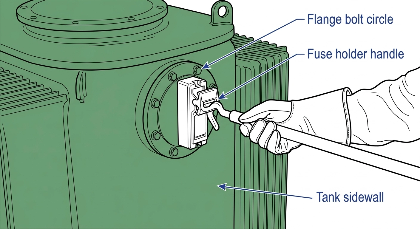
The well housing threads or bolts into the tank wall opening, with a flange gasket providing the primary oil seal. Because this seal sits below oil level, any installation error here doesn’t just risk a leak — it risks moisture and air ingress into the oil-filled compartment, which affects the transformer’s overall insulation system, not just the fuse assembly.
Cross-section of a sidewall-mounted Bay-O-Net assembly showing well housing, flange gasket, fuse holder, and hot-stick engagement point.
Fuse Holder and Hot-Stick Interface
The removable fuse holder inserts into the well and engages a contact assembly designed for hot-stick operation, allowing field crews to change a blown fuse without de-energizing or draining the transformer. This is where insertion depth tolerance becomes critical — under-insertion leaves marginal contact area, while over-insertion can stress the internal contact spring beyond its designed travel.
Mounting Flange Alignment and Gasket Seating Tolerances
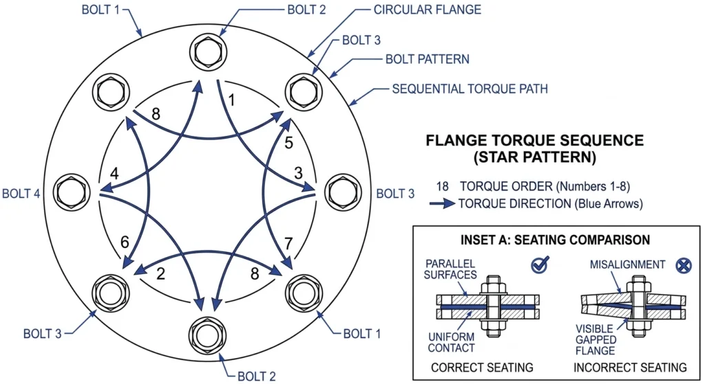
“How much misalignment is acceptable on the flange bolt pattern?” Generally none, by design — the flange is a matched-hole pattern, so if bolts require forcing or the housing sits at a visible angle relative to the tank wall, stop and check for a bent flange, damaged threads, or a mismatched housing before proceeding. Forcing a misaligned flange into place pre-stresses the gasket unevenly, which shows up later as a slow weep rather than an immediate failure.
“How do I know the gasket is seated correctly before torquing bolts?” The gasket should sit fully within its retention groove with no visible pinch point or twist before any bolt contacts it. A gasket that’s partially outside the groove on one side will compress unevenly once torqued, even if the final torque value on every bolt reads correct.
[Expert Insight: Gasket Seating Sequence]
Hand-tighten all bolts first in a cross pattern before applying final torque to any single bolt — this prevents the flange from cocking to one side mid-installation
A gasket that has been compressed once (even briefly) during a trial fit should generally not be reused — it may have already taken a partial compression set
Bolt Torque: What “Correct” Actually Means Here
Sidewall flange bolt torque values vary by assembly size, thread class, and gasket material, so the single most important field rule is: torque to the value on the manufacturer’s nameplate or installation sheet, never to a generic figure carried over from another assembly. Over-torquing on a cast housing can crack the flange at the bolt boss; under-torquing leaves the gasket under-compressed, and under-compression on a below-oil-level seal is far more consequential than the same error on an above-oil terminal connection.
Correct cross-pattern torque sequence on a sidewall flange bolt circle, with a callout comparing aligned vs. cocked flange installation.
Because the flange sits below the oil line, a bolt that backs off even slightly under thermal cycling doesn’t just risk an external leak—it risks drawing in moist ambient air on the cooling cycle, which is why re-torque checks on this specific joint are typically written into commissioning checklists even when no other transformer accessory gets the same treatment.
Re-check torque after the transformer’s first full thermal cycle (initial energization through a full load/no-load swing) rather than assuming installation-day torque holds indefinitely — gasket compression set during the first thermal cycle is normal and expected, not a sign of a defective gasket.
Fuse Holder Insertion Depth and Contact Engagement
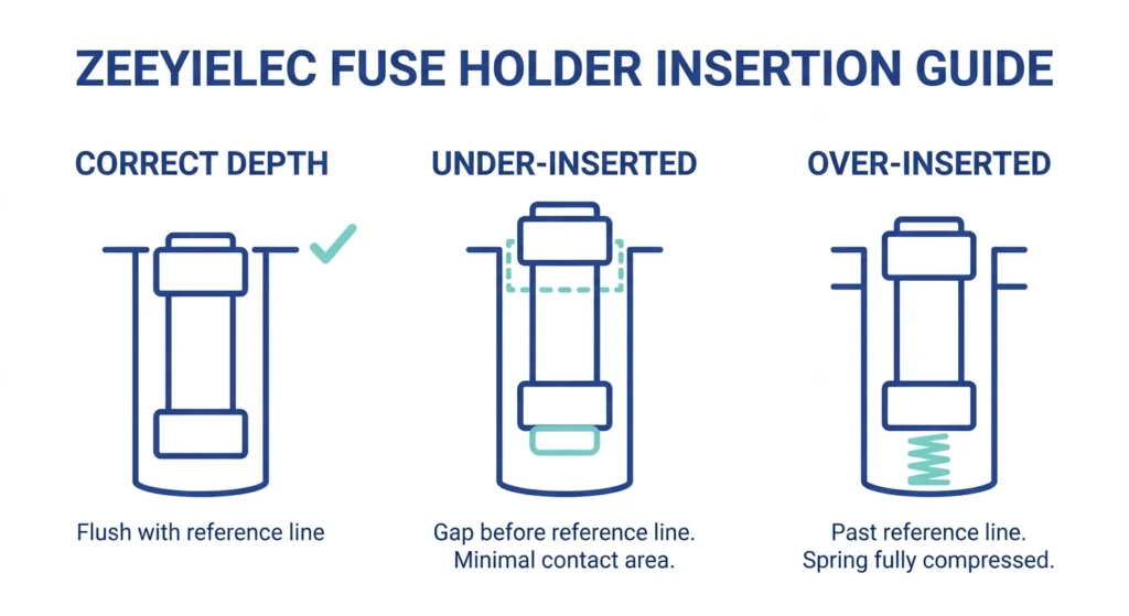
Insertion depth determines how much contact surface area exists between the fuse holder and the well’s internal contact assembly. Too shallow, and the contact engagement area is reduced, creating a resistive hot spot under load current. Too deep, and the holder can bottom out against the well’s internal stop, pre-loading the contact spring beyond its intended travel and accelerating spring fatigue.
Side-by-side comparison of correct insertion depth versus under-insertion and over-insertion, with contact engagement area highlighted.
Most manufacturers mark a reference line or shoulder on the fuse holder body indicating full seated depth. On ZeeyiElec’s Bay-O-Net sidewall assembly (Drawing 12ZY1015015), the wall hole is machined to ø57 ±0.1mm and overall assembly dimensions carry a general reference tolerance of ±5mm — a holder that seats with resistance well outside this range, or that doesn’t reach the reference line under normal hand pressure, should be checked against the drawing rather than forced.
[Expert Insight: Reading a “Stuck” Fuse Holder Correctly]
A holder that seats with unusual resistance partway through insertion often indicates internal contact misalignment, not just tight tolerances — don’t force it
Document insertion resistance at commissioning; a holder that seats progressively harder over successive fuse changes suggests contact wear worth flagging to engineering
Common Installation Errors vs. Acceptable Tolerance
Field Comparison Table
Finding
Within Tolerance
Requires Correction
All flange bolts torqued to nameplate value, cross-pattern sequence followed
✓
One or two bolts hand-tight only, rest at spec
✓
Gasket fully seated in groove, no visible pinch
✓
Gasket partially outside groove on one edge
✓
Fuse holder seats flush at reference line, moderate hand pressure
✓
Fuse holder requires forcing or stops short of reference line
✓
Flange sits flush and square against tank wall
✓
Visible gap or angle between flange and tank wall
✓
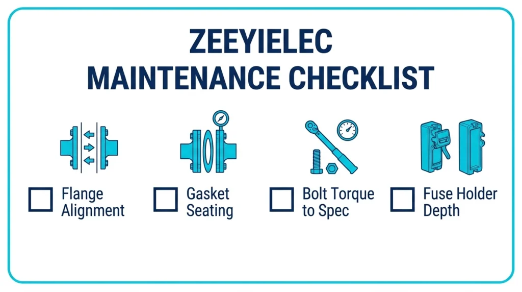
Quick-reference field checklist card summarizing the four tolerance checkpoints: flange alignment, gasket seating, bolt torque, and fuse holder depth.
When Should I Escalate an Installation Tolerance Question?
Escalate to engineering or the supplier rather than proceeding when: the flange bolt pattern doesn’t align with the tank cutout despite correct part numbers, torque values aren’t available on the nameplate or documentation for the specific assembly on hand, or a fuse holder shows resistance that doesn’t resolve after re-checking alignment and cleaning the contact surfaces.
For sourcing, matching the exact Bay-O-Net series to the tank cutout and voltage class matters more than matching by general appearance. ZeeyiElec’s transformer accessories range covers Bay-O-Net fuse assemblies, current limiting fuses, and bushings built to documented mounting specifications, and our team can help cross-reference an installation issue against the original product drawing. For broader accessory selection decisions, see the transformer accessories selection guide.
Frequently Asked Questions
What torque value should I use for a Bay-O-Net sidewall flange?
Torque values are specific to the assembly’s bolt size, thread class, and gasket material, so always use the value on the manufacturer’s nameplate or installation documentation rather than a generic figure carried over from a different assembly.
Can I reuse a gasket after a trial-fit and removal?
Generally no — a gasket that has been compressed even briefly during a trial fit may have taken a partial compression set, which can prevent it from sealing evenly once final torque is applied.
How soon after installation should I re-check flange bolt torque?
Re-check after the transformer’s first full thermal cycle (initial energization through a load/no-load swing), since some gasket compression set during that first cycle is normal and expected.
What does it mean if the fuse holder won’t seat flush?
It usually indicates a misaligned contact, debris in the well, or an incorrect holder for that well size — don’t force it, since forcing can damage the internal contact spring.
Is a small gap between the flange and tank wall ever acceptable?
No — any visible gap or angle indicates the flange isn’t drawing down evenly, which will compress the gasket unevenly even if every bolt reads correct torque.
Who should I contact if torque specifications aren’t on the nameplate?
Contact the supplier or manufacturer directly with the model/series number rather than estimating — using an incorrect torque figure on a below-oil-level seal carries more risk than waiting for the correct specification.
yoyo shi
Yoyo Shi writes for ZeeyiElec, focusing on medium-voltage accessories, transformer components, and cable accessory solutions. Her articles cover product applications, technical basics, and sourcing insights for global electrical industry buyers.






 English
 한국어
한국어 العربية
 Español
 हिन्दी
 தமிழ்
தமிழ் Deutsch (Sie)
 Français
 Português do Brasil
 Русский