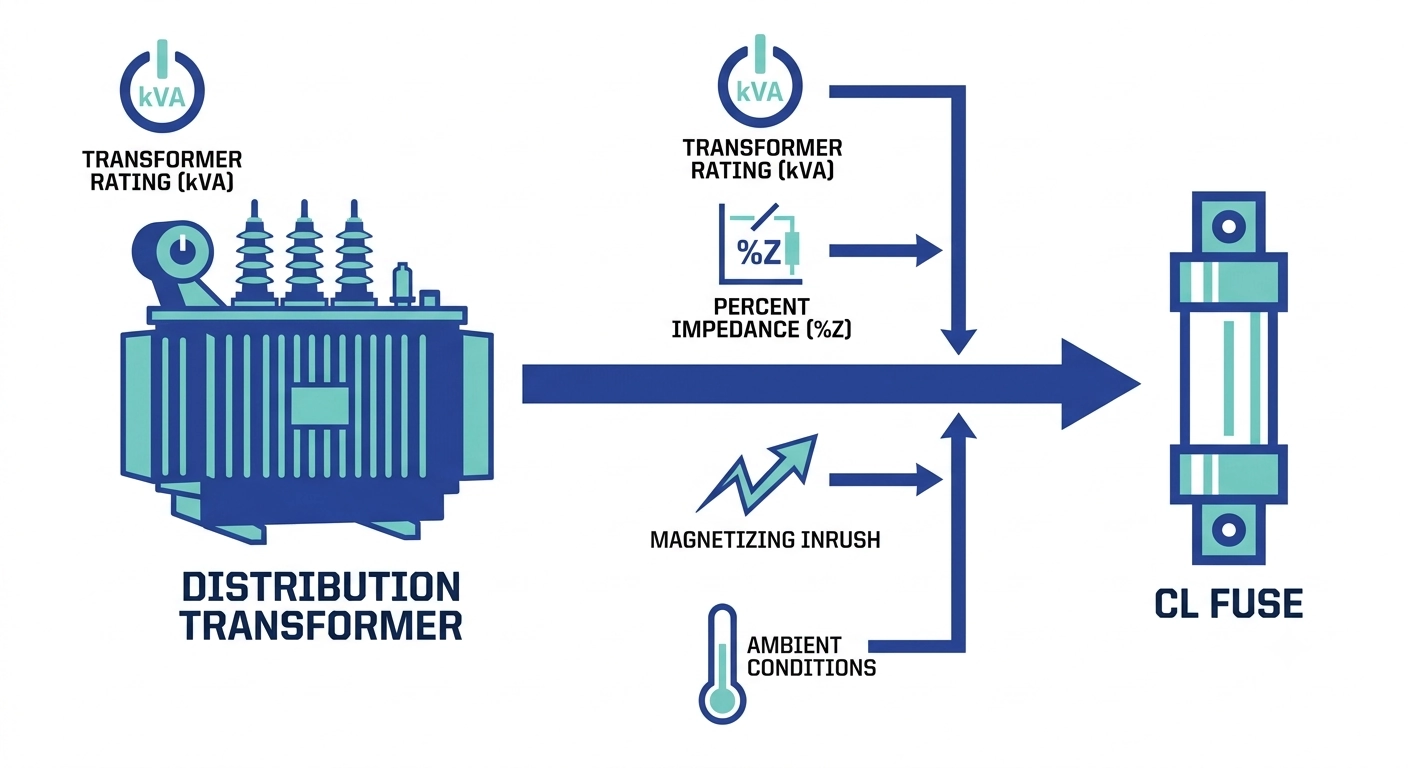
CL fuse rating transformer matching means combining full-load current, impedance (%Z), and inrush profile — not just kVA and voltage — then verifying the result against the fuse’s time-current curve and upstream coordination. Skipping any one input typically produces nuisance operation or delayed fault clearing.
What Determines a Correct CL Fuse Rating
The Role of a CL Fuse in the Protection Chain
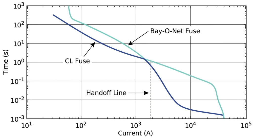
In a two-stage distribution transformer protection scheme, the CL fuse is the backup device, positioned to interrupt high-magnitude internal faults that exceed what an expulsion-type Bay-O-Net fuse can safely clear. It typically operates within a half-cycle on faults in the 4,000 A–50,000 A range, cutting current off before peak let-through energy reaches the winding.
Why Nameplate Data Alone Isn’t Enough
The nameplate gives kVA, HV/LV voltage, and vector group — enough to calculate full-load amperes, but not enough to size a fuse correctly. Two additional data categories matter: inrush current magnitude/duration at energization, and impedance percentage (%Z), which shapes both inrush and through-fault current. A transformer with %Z in the 4%–6% range produces meaningfully different through-fault current than one near 8%, shifting where the fuse’s minimum melt point needs to sit. Sizing from kVA/voltage alone is a common source of later coordination problems.
Fuse selection has to stay inside the transformer’s transformer accessories protection scheme as a whole, since upstream and downstream devices share the same fault-current spectrum.
Step-by-Step: Pulling the Required Transformer Parameters
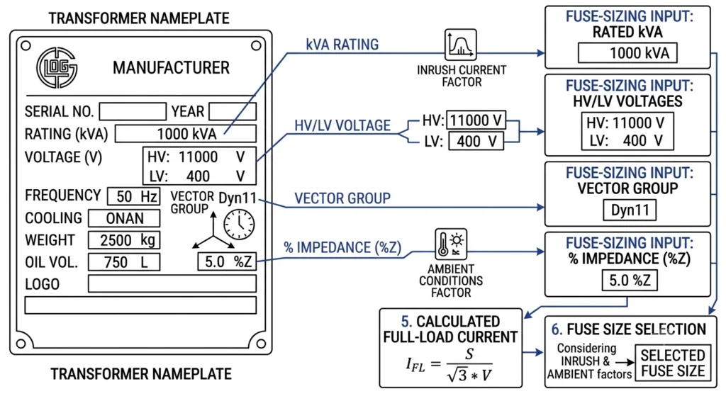
Transformer nameplate data — kVA, HV/LV voltage, and vector group — provides the starting parameters for calculating full-load current in fuse sizing.
kVA, HV Voltage, and Vector Group
Start with kVA rating, HV-side voltage, and vector group. A 1,000 kVA transformer at 34.5 kV HV sits in a very different current range than the same kVA at 12.47 kV — fuse ampere class shifts accordingly even though power rating hasn’t changed.
Full-Load Current Calculation
For a three-phase transformer: IFLA = (kVA × 1000) / (√3 × VHV)
Example: a 1,000 kVA transformer at 12.47 kV HV gives IFLA ≈ 46.3 A.
The fuse’s continuous rating is then selected as a multiple of this figure, covered next.
Inrush and Through-Fault Data
Pull inrush current magnitude and duration (as a multiple of I_FLA over a stated number of cycles) and %Z from the transformer’s factory test report. A %Z of 5.75% with inrush near 8–12× I_FLA for the first few cycles is a realistic mid-size distribution profile, though values vary by design.
With kVA, HV voltage, %Z, and inrush profile in hand, sizing can proceed without guesswork. This same data feeds the transformer accessories RFQ checklist when the fuse is ordered alongside other accessory families.
Expert Insight
Request the factory test report — %Z and inrush rarely appear on the nameplate.
Inrush duration matters as much as magnitude on the TCC curve.
If test data is unavailable, treat sizing as provisional, not final.
Matching Full-Load and Overload Current to Fuse Rating
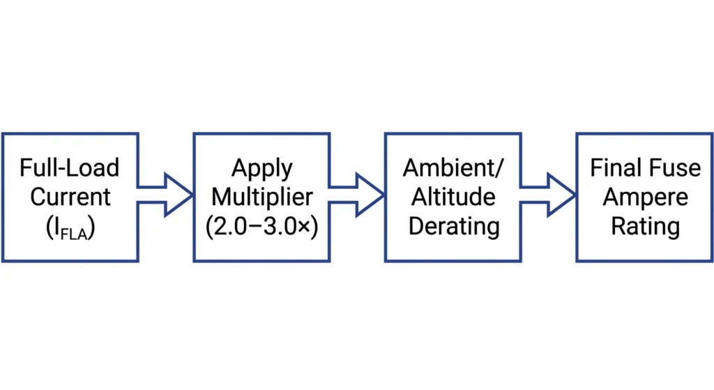
The fuse continuous rating is derived by applying a sizing multiplier of 2.0 to 3.0 times full-load current, then adjusting for ambient derating.
Standard Sizing Multipliers
A CL fuse continuous rating is typically set at 200%–300% of I_FLA — enough margin above inrush and short-duration overload without pushing the melt curve so far right that clearing slows down. Units with heavy motor-starting duty sit toward the higher end; stable, lightly loaded units sit closer to 200%.
Sizing range: Ifuse ≈ 2.0–3.0 × IFLA
Example: 46.3 A × 2.2 ≈ 102 A → next standard catalog rating selected, then verified against TCC margin above inrush.
Ambient Temperature and Altitude Derating
Fuse capacity is rated at a standard ambient, commonly 40°C, dropping as ambient rises. A site at 50°C ambient can require a 10%–15% upward correction, and elevations above 1,000 m typically need an additional factor since reduced air density affects cooling and dielectric withstand. [VERIFY STANDARD: derating table reference] against the specific fuse datasheet rather than a fixed percentage.
The derated figure should be cross-checked against related cable accessories RFQ data if cable-side accessories are specified in the same order, keeping voltage class and current rating consistent across the package.
Verifying Inrush Withstand and TCC Curve Margin
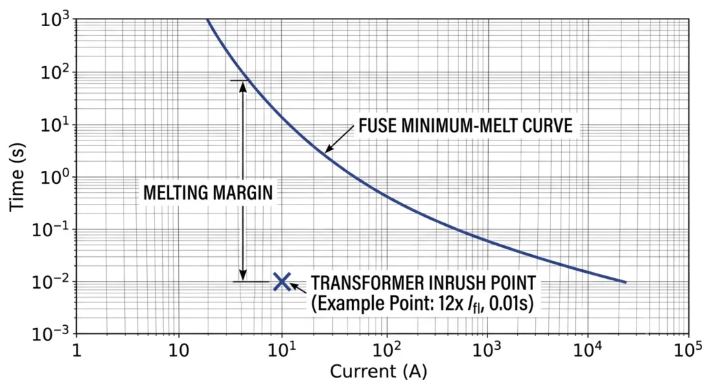
A valid CL fuse rating places the transformer’s inrush point clearly below and left of the fuse’s minimum melt curve on the TCC plot.
Reading the Minimum Melt Curve
The fuse’s minimum melt curve plots current-time combinations where the element begins to melt. The transformer’s inrush point — typically 8–12× I_FLA for a fraction of a second to a few cycles — must fall clearly below and left of this curve. Field practice targets a melt time at the inrush level several times longer than the inrush duration itself, though the exact safety factor varies by manufacturer.
Inrush Multiplier Reference Point
An 8–12× I_FLA for 0.1 second benchmark is a common starting checkpoint referenced in fuse manufacturer TCC documentation, but the precise multiplier/duration pairing varies by product line, so it should be confirmed against the specific fuse’s published curve before finalizing.
Interrupting rating and TCC requirements for distribution-class CL fuses are governed by the IEEE C37.41 fuse standard; cross-referencing that standard against the manufacturer’s published curve is standard practice on projects also drawing from the transformer accessories selection guide.
Coordinating CL Fuse Rating with Upstream and Downstream Protection
Two-stage protection coordination overlays Bay-O-Net and CL fuse TCC curves to confirm each device clears its designated portion of the fault spectrum.
Field Case — Mis-Coordinated CL Fuse on a Pad-Mount Unit
On a 750 kVA pad-mounted transformer, a CL fuse correctly sized against I_FLA and inrush data was specified without rechecking the upstream recloser’s fast-trip curve. During a downstream fault, the recloser tripped ahead of the fuse, de-energizing a wider feeder section before the fault could be isolated. The fuse rating wasn’t wrong for the transformer — it was wrong for its position in the coordination sequence, which only surfaced once curves were overlaid.
Confirming Selectivity Upstream
Selectivity means the CL fuse clears the fault before the upstream device trips, across the fuse’s full interrupting range — commonly up to 40,000 A–50,000 A symmetrical. This requires plotting both curves across the entire fault-current spectrum, since coordination holding at 10,000 A can fail at 30,000 A if curves cross. This is also where the fuse’s relationship to the transformer’s own Bay-O-Net fuse assembly gets confirmed — the two devices divide the fault spectrum rather than overlap.
Expert Insight
Plot curves across the full fault-current range — crossovers often occur at unexpected points.
Treat Bay-O-Net and CL fuse as a matched pair, not two independent decisions.
Re-verify coordination whenever upstream recloser or relay settings change.
Common CL Fuse Sizing Mistakes in the Field
Three patterns account for most mis-sized fuses found in field failure investigations, and all trace back to skipped data rather than a flawed method.
Undersizing from Nameplate-Only Specification
Sizing from kVA and voltage alone, without %Z or inrush data, tends to produce a rating that nuisance-clears during normal energization — the most common mistake, since the test report often has to be requested separately under deadline pressure.
Ignoring Inrush on High-Impedance Units
Transformers with %Z reaching 7%–8% can produce inrush profiles that differ meaningfully from the 8–12× I_FLA benchmark. Applying a standard multiplier without checking actual data risks a rating too close to the inrush curve, occasionally nuisance-tripping under conditions like cold-load pickup.
Overlooking Ambient/Altitude Correction
A rating correct at 40°C ambient can underperform at sites above 45°C or 1,000 m elevation. This step is the one most often dropped between calculation and purchase order, usually because ambient/altitude data isn’t included in the spec package handed to the person sizing the fuse.
RFQ Data Checklist for Ordering the Right CL Fuse
Getting CL fuse rating transformer matching right at the RFQ stage means gathering this data before submission so quotations return matched to the actual transformer:
Transformer kVA rating and HV-side voltage
Full-load amperes (calculated or from test report)
Impedance (%Z) and inrush profile (magnitude × duration)
Site ambient temperature range and altitude
Upstream protective device TCC curve
Existing Bay-O-Net fuse rating, if two-stage protection applies
Required interrupting rating for maximum available fault current (commonly up to 40,000 A–50,000 A symmetrical)
Supplying this upfront avoids the clarification cycle that otherwise adds 1–2 weeks before manufacturing can be scheduled.
For CL fuse specifications and interrupting ratings currently available, see ZeeyiElec’s current limiting fuses product page. Technical teams can also submit the parameter set above for a coordination check before an order is finalized.
Frequently Asked Questions
What CL fuse rating should I use for a 500 kVA transformer?
Sizing depends on full-load amperes and the applicable multiplier for the transformer type, so a 500 kVA unit at typical distribution voltages commonly lands in a mid-range ampere class, but the exact figure needs confirmation against the fuse manufacturer’s TCC curve and site derating conditions.
Can a CL fuse be sized directly from the transformer nameplate?
The nameplate gives kVA and voltage ratio for calculating full-load current, but it doesn’t capture inrush magnitude, ambient conditions, or upstream coordination, so nameplate data is a starting point rather than a complete sizing basis.
What happens if a CL fuse rating is too low?
An undersized fuse tends to operate on normal inrush or moderate overload, causing nuisance outages rather than protecting against genuine faults, and repeated operation can degrade the fuse element over time.
What happens if a CL fuse rating is too high?
An oversized fuse may fail to clear a fault quickly enough, letting thermal and mechanical stress reach the winding before interruption, which raises the risk of internal damage during a fault event.
Does altitude or ambient temperature affect CL fuse sizing?
Yes, both reduce a fuse’s effective current-carrying capacity, so high-altitude or elevated-ambient installations generally need a correction factor applied before final selection.
How does inrush current affect CL fuse selection?
Energization produces a brief, high-magnitude inrush current, and the fuse’s minimum melt curve must sit above that inrush point with adequate margin, or the fuse will nuisance-trip on every energization.
Should CL fuse rating be coordinated with the Bay-O-Net fuse?
Yes, in a two-stage scheme the CL fuse handles faults beyond the Bay-O-Net’s clearing range, so their TCC curves need to be checked together for a clean handoff rather than sized in isolation.
yoyo shi
Yoyo Shi writes for ZeeyiElec, focusing on medium-voltage accessories, transformer components, and cable accessory solutions. Her articles cover product applications, technical basics, and sourcing insights for global electrical industry buyers.




 English
 한국어
한국어 العربية
 Español
 हिन्दी
 தமிழ்
தமிழ் Deutsch (Sie)
 Français
 Português do Brasil
 Русский