Loadbreak switch selection by network topology comes down to one core question: does the network feed one direction, two directions, or three or more branches? The answer — radial, loop-fed, or multi-branch — determines how many switching positions a loadbreak switch needs and how it will actually be operated in the field. Get the topology-to-configuration match wrong, and the mismatch tends to surface at the worst possible time: during a loop restoration, or mid-commissioning when a switch simply can’t perform the sequence the network requires.
Radial Topology
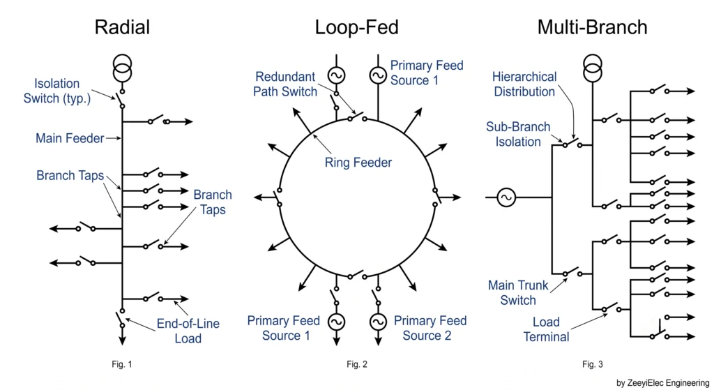
In a radial system, a single source feeds one or more transformers along a linear path with no alternate feed. Power flows in one direction, so isolation at any point typically requires just a single make/break position. Two-position switches dominate here, commonly rated 630 A continuous at 15/25 kV or 38/40.5 kV class — a natural fit for the pad-mounted transformers found in rural and light-industrial distribution, where operational simplicity outweighs redundancy.
Loop-Fed (Ring-Main) Topology
A loop-fed system connects a transformer to two possible source directions, forming a ring that can be opened or closed at designated points for maintenance or fault isolation. This bidirectional supply is why loop topology generally calls for four-position sectionalizing switches rather than two-position units: the extra positions let an operator isolate a faulted section while restoring service to the rest of the loop from the opposite direction.
Multi-Branch / Junction Topology
Multi-branch configurations occur where three or more feeder sections converge at a single transformer or switching cabinet. Here, switch selection depends on branch count as much as voltage class — a three-way junction may work fine with a four-position switch, but additional branches beyond that can require ganged switch assemblies rated for the combined downstream load.
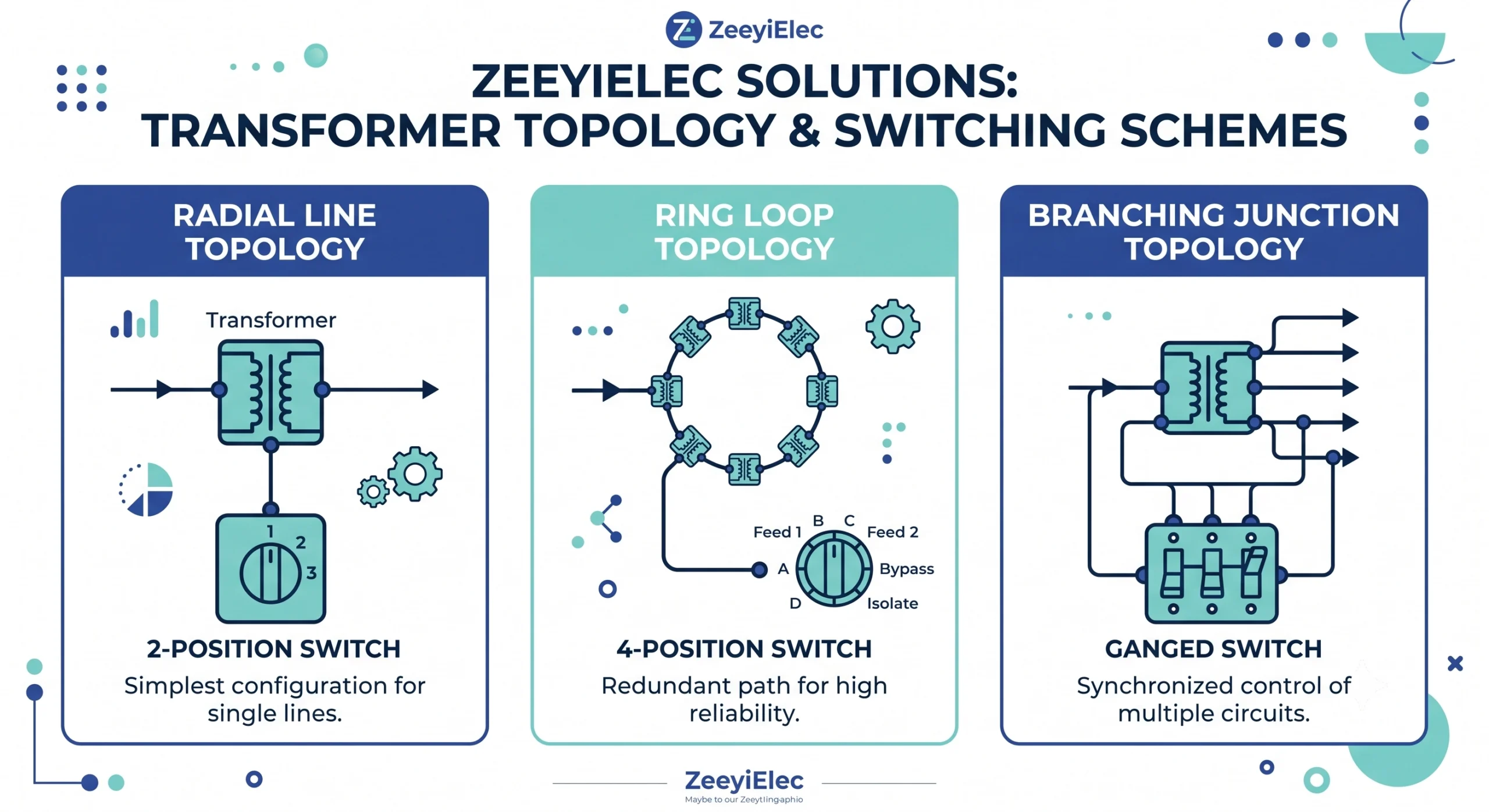
Three network topology types — radial, loop-fed ring-main, and multi-branch junction — each require a distinct loadbreak switch position count.
Expert Insight: Topology Selection Patterns
Radial topology accounts for the majority of ZeeyiElec’s distribution transformer support requests — simplicity, not redundancy, drives that volume.
Loop restoration failures more often trace back to switching sequence errors than to equipment defects.
Branch count added late in project design is the single most common reason a switch order needs revision before shipment.
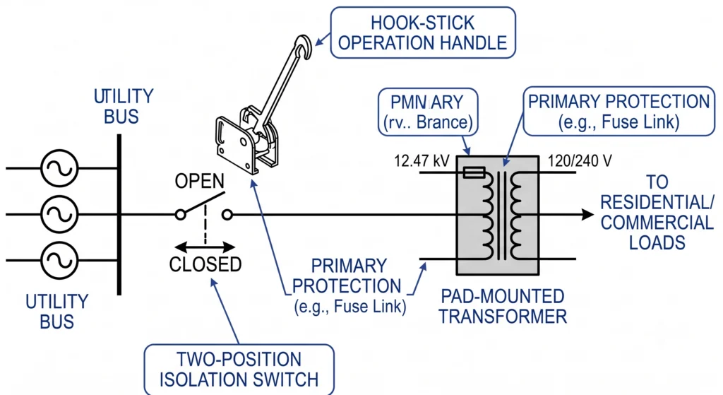
Radial feeders are the most common topology in distribution transformer projects, and two-position loadbreak switches are the standard fit — a single open/closed isolation point matching the feeder’s one-directional power flow.
A two-position loadbreak switch provides a single isolation point on a radial feeder, matching the feeder’s one-directional power flow.
Current Rating and Voltage Class
Two-position switches for radial applications typically run 630 A continuous, at 15/25 kV or 38/40.5 kV depending on system design. A switch rated for 15/25 kV service installed on a 38/40.5 kV feeder won’t meet basic insulation level requirements — a mismatch that tends to surface during commissioning tests rather than at initial inspection, since undersized voltage class selection is a recurring rework cause on pad-mounted transformer projects.
Phase Configuration
Single-phase taps off a 3-phase radial backbone are common in rural distribution, where a 1-phase loadbreak switch handles the tap point while the main feeder continues on 3-phase hardware. Assuming 3-phase as a default without checking the load schedule is a recurring gap at the RFQ stage.
Mounting and Operation
Hook-stick operation for manual switching from ground level is standard, keeping operator clearance requirements aligned with typical utility line-crew procedures. Stored-energy quick-action mechanisms are common on current-generation switches, reducing arc duration during load interruption compared to slow-break designs, in line with the make/break performance requirements set out in IEC 62271-103 for switches rated above 1 kV.
Radial topology’s relative simplicity makes selection largely a matter of matching current rating, voltage class, and phase count to the feeder’s actual operating parameters. The full loadbreak switch series covers these variations, and the transformer accessories category provides broader context on how switches fit alongside bushings and fuses in a complete specification.
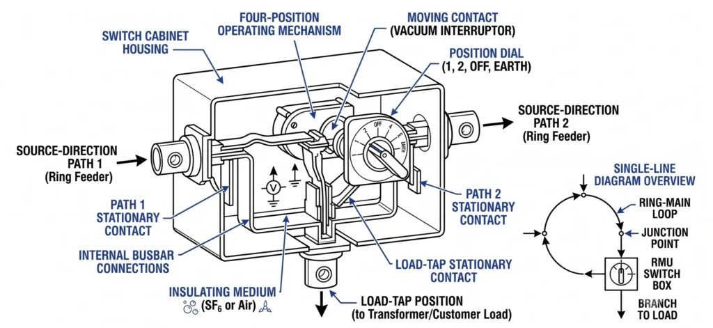
Where radial topology asks a switch to do one job — open or close a single point — loop-fed systems ask it to manage two directions of supply. That structural difference is the entire reason four-position sectionalizing switches replace two-position units in ring-main applications.
A four-position sectionalizing switch at a ring-main junction allows isolation and restoration across both source directions of the loop.
Normal Loop Operation
Under normal conditions, a loop-fed transformer typically runs with one direction of the loop closed and supplying load, while the opposite direction sits open as a standby path — an open-point configuration. Four-position switches rated at 630 A continuous, 15/25 kV or 38/40.5 kV class, are the standard fit, matching current ratings used in radial systems but adding the positions needed for directional control. Continuous current rating alone doesn’t tell the full story, though — the switch also needs to handle the interrupting duty associated with load transfer between loop directions, which manufacturers often rate separately from continuous capacity.
Loop Restoration / Switching Sequence
When a fault occurs on one section of the loop, restoration follows a specific sequence: isolate the faulted section first, then close the alternate-direction position to restore supply from the opposite source. Sequence matters more than it might seem — closing the alternate feed before fully isolating the fault risks paralleling two live sources through the faulted section, which can drive fault current past the switch’s rated short-time withstand current as defined in IEC 62271-1 and referenced in IEC 62271-103. Field crews commissioning loop systems generally walk through this sequence during energization testing rather than relying on nameplate ratings alone, since procedural errors cause more loop-restoration incidents than equipment failure does.
Loop topology’s reliability advantage — maintaining service during single-section faults — depends entirely on selecting a configuration that matches its dual-source structure. Specifying a two-position unit at a true ring-main junction eliminates that advantage regardless of current rating. The distinction between switching devices is also worth understanding at the product level, since loadbreak switches and off-circuit tap changers are frequently confused despite serving entirely different functions.
Multi-Branch and Junction Point Configurations
Multi-branch topology occurs where three or more feeder sections converge at a single transformer or switching cabinet, and here selection depends on branch count as much as voltage class or current rating. A junction serving two branches may function adequately with a standard four-position switch, but each additional branch typically requires either a higher-position switch assembly or multiple units ganged together at the same cabinet.
Three-Way Junction Cases
A three-way junction — one incoming feed and two outgoing branches, or two incoming directions plus one load tap — is the most common multi-branch case in distribution design. These are frequently specified with 630 A, four-position switches when total branch load stays within the switch’s continuous rating, but current rating verification against combined downstream load is necessary before finalizing selection. A three-way junction sized correctly for present load conditions can still create a bottleneck if a fourth branch is added later without re-verifying interrupting capacity.
Expandable / Future-Branch Provisioning
Projects anticipating network growth sometimes specify switch cabinets with spare positions or oversized current ratings to accommodate future branches without full replacement. That decision trades higher upfront cost for reduced future disruption, and the right call depends on the utility’s or EPC’s growth timeline rather than a fixed engineering rule.
Selecting switch configuration for multi-branch topology is less standardized than the radial or simple loop cases, since branch count, load distribution, and growth planning all factor in simultaneously. The transformer accessories selection guide is a useful starting point for working through these combinations rather than defaulting to a standard four-position unit regardless of branch count.
Expert Insight: Multi-Branch Verification Points
Verify combined downstream load at every branch before finalizing current rating — not just the load present at order time.
Spare-position provisioning is a cost-versus-disruption decision, not a default specification.
Re-check interrupting capacity whenever a branch is added post-installation, even if continuous current still looks adequate on paper.
Field Switching Sequence and Installation Considerations by Topology
Switching sequence and installation clearance shift with topology, and these field-level details often carry more practical weight than nameplate ratings. A switch correctly specified on paper can still create operational problems if clearance or procedure doesn’t account for the topology it serves.
Hook-Stick Clearance by Topology
Hook-stick operation is standard across radial, loop, and multi-branch installations at pad-mounted locations, but the physical clearance required around the cabinet increases with topology complexity. Radial installations generally need clearance for a single approach angle. Loop and multi-branch cabinets often require access from two or more sides — typically 0.9–1.2 m of working clearance per accessible side, depending on enclosure dimensions — because operators must reach multiple position handles during a restoration sequence. Clearance shortfalls in confined utility vaults sometimes surface only when the full switching sequence is walked through during energization testing, not during the initial site survey.
Switching Sequence Verification
For radial systems, verification is straightforward: confirm the single position opens and closes cleanly under rated load current. Loop and multi-branch topologies require a documented sequence — isolate first, verify de-energization, then close the alternate position. Skipping verification between those two steps is a documented cause of fault-transfer incidents, since paralleling two live sources through an unverified section can push fault current beyond the switch’s short-time withstand rating.
Environmental and Moisture Considerations
Pad-mounted cabinets in loop and multi-branch configurations also tend to have more cable entries and gasket penetrations than simple radial cabinets, which increases potential moisture ingress points. Routine maintenance inspection typically checks gasket condition at each cable entry, particularly in installations exposed to seasonal flooding or high humidity, where degraded sealing can introduce insulation issues over a multi-year service period. Cable entries requiring environmental sealing are commonly paired with heat shrink cable accessories at these junction points.
Matching installation practice to topology — not just matching switch rating to topology — is what determines whether the theoretical reliability advantage of loop or multi-branch configurations actually holds up in service.
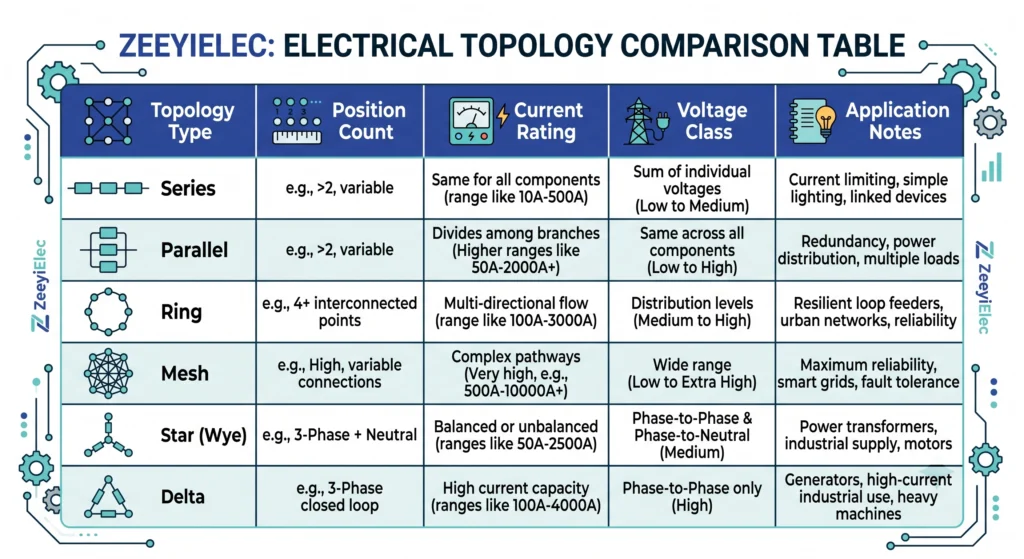
Comparison Table: Topology vs Switch Configuration vs Rating
The selection logic above comes down to three variables working together: topology type, switch position count, and current/voltage rating. The table below consolidates it into a single reference.
This selection matrix maps topology type to recommended switch position count, current rating, and voltage class for quick specification reference
Topology-to-Configuration Selection Matrix
Topology Type
Position Count
Current Rating
Voltage Class
Application Notes
Radial feeder
Two-position
630 A
15/25 kV or 38/40.5 kV
Single isolation point; hook-stick operation standard
Loop-fed (ring-main)
Four-position
630 A
15/25 kV or 38/40.5 kV
Dual-direction sectionalizing; verify interrupting rating for fault-transfer duty
Multi-branch (3-way)
Four-position (min.)
630 A, verify against combined load
15/25 kV or 38/40.5 kV
Confirm downstream branch load before finalizing; consider future-branch provisioning
Multi-branch (4+ way)
Ganged multi-position
Project-specific
Project-specific
Typically requires custom cabinet design and individual verification
These figures reflect continuous current ratings under normal operating conditions; interrupting and short-time withstand ratings are separate parameters that must be verified independently, particularly for loop and multi-branch topologies where fault-transfer duty exceeds simple load-break switching. IEC 62271-103 governs performance requirements for alternating-current switches rated above 1 kV and up to 52 kV, including the load-break switching devices covered here, with rated short-time withstand current values defined by reference to IEC 62271-1.
Treat this table as a starting reference rather than a final specification — actual branch load, growth planning, and site clearance still need verification against the project’s single-line diagram before a configuration is finalized.
Common Selection Mistakes and How to Get Topology-Matched Recommendations
The most frequent error in loadbreak switch selection isn’t a rating mismatch — it’s specifying position count out of habit rather than topology. Teams accustomed to sourcing two-position switches for radial feeders sometimes apply the same default to a loop-fed junction, only discovering the mismatch when loop restoration requires isolating both directions and the switch simply can’t do it.
A second common gap is branch-count drift: multi-branch junctions specified early in a project often gain an additional feeder during detailed design, but the switch order isn’t revisited to confirm position count and current rating still match the updated load. A third recurring issue is voltage class assumption — defaulting to 15/25 kV without confirming against the actual system voltage, a mistake that surfaces as an insulation-level failure during commissioning rather than at order placement.
Each of these traces back to the same root cause: switch selection made without first confirming topology, branch count, and load distribution against the single-line diagram.
For projects where topology or branch configuration isn’t fully finalized, sharing the single-line diagram alongside voltage class and expected load lets ZeeyiElec’s technical team confirm switch configuration before quotation rather than after installation. Request a quote with your project’s topology details through the loadbreak switch product page.
Frequently Asked Questions
What type of loadbreak switch is used for a radial feeder?
Radial feeders typically use two-position loadbreak switches rated for single-point isolation, since only one source feeds the load under normal conditions, though branch count and future expansion plans can shift this toward a four-position design.
Why do loop-fed systems need four-position switches instead of two-position?
Loop-fed systems require switching between two source directions during fault isolation or maintenance, and a four-position switch allows this dual-source sectionalizing without de-energizing the entire loop, provided the switch’s interrupting rating matches the loop’s fault current.
Can a two-position switch be used in a ring-main system?
A two-position switch can be used at a dead-end tap off a ring main, but it cannot perform loop sectionalizing at a true ring-main junction, so position within the loop determines whether two- or four-position hardware applies.
How does branch count affect loadbreak switch selection?
Additional branches at a junction generally increase the required switch position count and may raise the necessary current rating, since each branch adds a potential load or fault path that the switch must isolate independently.
Is hook-stick operation suitable for all topology types?
Hook-stick operation is common across radial, loop, and multi-branch installations at accessible pad-mounted locations, but clearance requirements and switching sequence complexity increase in loop and multi-branch setups, which can affect operator training needs.
What happens if the wrong switch configuration is selected for a loop topology?
Selecting a two-position switch where loop sectionalizing is required can force full outages during maintenance that a properly configured four-position switch would avoid, and it may also create fault-isolation gaps depending on the loop’s protection coordination scheme.
Does voltage class change with network topology?
Voltage class is determined by the distribution system design rather than topology itself, so radial, loop, and multi-branch configurations can each appear at similar voltage classes, with topology mainly influencing position count and switching sequence rather than voltage rating.
yoyo shi
Yoyo Shi writes for ZeeyiElec, focusing on medium-voltage accessories, transformer components, and cable accessory solutions. Her articles cover product applications, technical basics, and sourcing insights for global electrical industry buyers.





 English
 한국어
한국어 العربية
 Español
 हिन्दी
 தமிழ்
தமிழ் Deutsch (Sie)
 Français
 Português do Brasil
 Русский