Cold shrink cable termination kits for MV underground cables must be matched to the cable, not picked from a catalog. The right kit has to match the cable’s voltage class, conductor area, outer diameter, insulation chemistry, and where the cable surfaces — miss any one and it won’t recover or grade the field correctly.
How Cold Shrink Terminations Work on MV Underground Cables
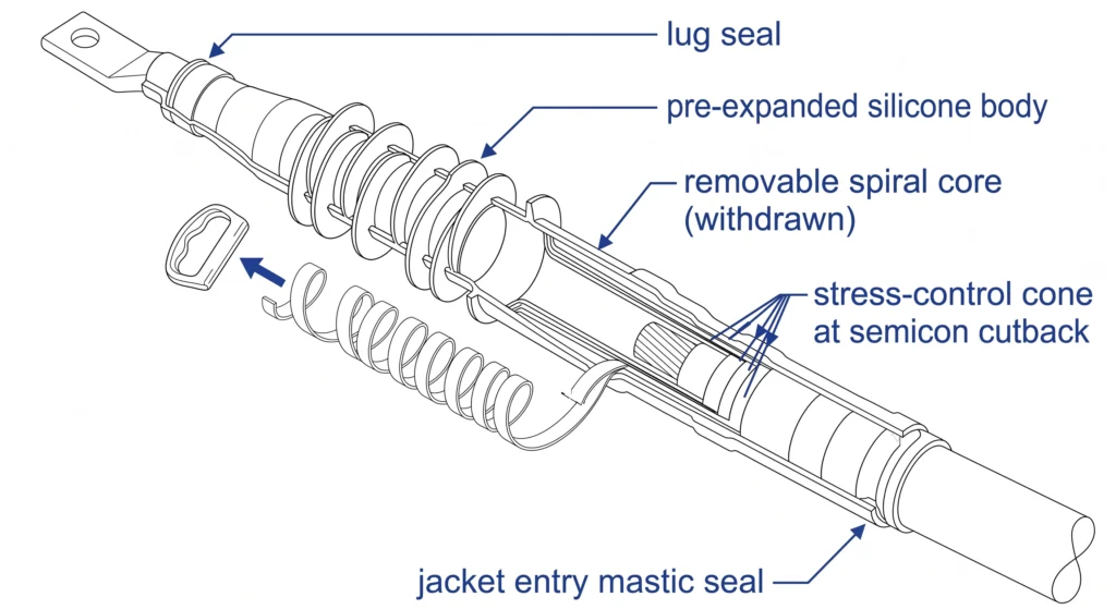
A cold shrink termination restores the insulation, grades the electric field, and seals the cable end without any applied heat. Instead of a torch, the kit relies on a pre-expanded silicone rubber (or EPDM) body held open by a removable internal support core. When the installer withdraws the core, the elastomer contracts radially onto the cable, generating continuous interface pressure that follows thermal expansion and contraction over a service life often targeted at 25–40 years. Four functional elements do the work.
Pre-expanded silicone insulation body
The silicone body re-establishes the radial insulation lost at cutback. Its constant residual squeeze keeps the interface void-free as load cycling moves the conductor — which is why cold shrink performs well in damp duct banks where heat-shrink installers struggle to apply even heat.
Removable support core
The spiral-wound plastic core is the defining mechanism. The installer positions the assembly, then unwinds the core so the body collapses onto the cable in one motion — no flame, no measured shrink temperature, no risk of scorching the primary insulation.
Stress-control (field-grading) element
At the cutback of the cable’s semiconductive screen, the electric field concentrates sharply. A high-permittivity stress-control layer redistributes that field; typical geometric stress cones or high-K materials operate with relative permittivity of roughly 15–30, smoothing a discharge-prone edge.
The unmanaged field at the screen edge can reach local gradients several times the bulk average; the grading element targets a surface tangential stress on the order of ≤ 0.5 kV/mm to suppress partial discharge inception. Interface radial pressure from the silicone is commonly held in the ≈ 0.05–0.15 N/mm² band to maintain a void-free interface across thermal cycles.
Environmental seal
Integral mastics and the silicone skirt block moisture ingress at the lug and the cable jacket entry — the dominant failure path underground. PD test criteria for this class are framed by the IEC 60502-4 cable-accessory family [VERIFY STANDARD: IEC 60502-4 termination test requirements], which governs type and routine testing rather than any single manufacturer’s claim.
Cross-section of a medium-voltage cold shrink termination identifying the pre-expanded silicone body, spiral support-core path, stress-control cone at the semiconductive cutback, and lug and jacket seals.
These elements explain why selection can’t reduce to voltage class alone — the focus of the cable accessories range and the criteria below.
How to Choose a Cold Shrink Kit: Selection Criteria
Five parameters decide whether a kit is usable on a given cable.
Voltage class matching
Match the kit to the cable’s rated voltage U₀/U and its maximum system voltage Um, not the nominal number alone. MV underground families typically split into an 8.7/15 kV class and a 26/35 kV class, with insulation and creepage sized accordingly.
Confirm that the kit’s rated Um ≥ the system’s highest voltage. An 8.7/15 kV (Um = 17.5 kV) kit must never be applied on a 26/35 kV (Um = 40.5 kV) circuit, even briefly during commissioning — the stress-control element is dimensioned for a specific gradient band.
Conductor size and cable OD fit window
This is where most field rejections originate. Cold shrink bodies recover only within a defined diameter band, so the measured OD over the insulation must fall inside the kit’s window. Conductor ranges commonly span 25–630 mm², reaching 800 mm² on primary feeders, but the governing number is the measured OD, not the copper area. Always measure the actual insulation diameter — datasheets and as-laid cables drift by 1–2 mm often enough to push a marginal selection out of range.
Indoor vs outdoor / underground transition type
A cable that stays in a duct or pit uses an indoor body; one that surfaces into air, sunlight, or pollution needs an outdoor variant with sheds and a tracking-resistant surface. Specifying an indoor kit at a riser pole is a recurring commissioning defect.
Insulation type compatibility
Confirm the kit is rated for the cable’s insulation — almost always XLPE or EPR on MV distribution. The semicon screen type (extruded vs taped) changes the cutback procedure, so verify it before cable prep, not at the splice.
[Expert Insight] Pre-RFQ selection check
Verify kit Um ≥ system maximum voltage before anything else.
Measure insulation OD in the field; don’t trust the datasheet figure.
Match the variant to where the cable surfaces (indoor vs outdoor shed profile).
Confirm XLPE/EPR and screen type before cutting back.
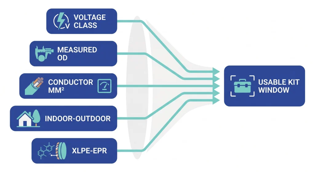
A selection decision map routing five cable inputs — voltage class, measured outer diameter, conductor area, indoor or outdoor exposure, and insulation type — toward a usable cold shrink kit window.
The Top 10 Cold Shrink Termination Kits (Selection Table)
These ten cold shrink cable termination kits are organized the way engineers specify — by voltage class and configuration, not by brand. Each row is grounded in real MV underground parameters; the part number falls out of the RFQ once cable OD and conductor area are fixed. Treat conductor ranges as typical bands, since the binding constraint is always measured OD against the kit window. Field note: on three-core jobs, crews routinely under-order breakout boots, so confirm the correct leg count before mobilizing.
15 kV-class underground kits (8.7/15 kV, Um = 17.5 kV)
#
Kit configuration
Conductor range
Indoor/Outdoor
Best-fit application
1
Single-core indoor termination
25–300 mm²
Indoor
Switchgear / RMU duct entry
2
Single-core outdoor termination
25–300 mm²
Outdoor
Riser pole, cabinet transition
3
Single-core heavy-feeder
400–630 mm²
Indoor/Outdoor
Primary distribution feeders
4
Three-core breakout set
35–240 mm²
Indoor
Three-core duct-bank entry
35 kV-class underground kits (26/35 kV, Um = 40.5 kV)
#
Kit configuration
Conductor range
Indoor/Outdoor
Best-fit application
5
Single-core indoor termination
50–400 mm²
Indoor
35 kV switchgear connection
6
Single-core outdoor termination
50–400 mm²
Outdoor
Substation riser / surface transition
7
Single-core heavy-feeder
500–800 mm²
Outdoor
Sub-transmission feeders
8
Three-core breakout set
70–300 mm²
Indoor/Outdoor
Three-core 35 kV duct entry
Deployment-specific underground sets
#
Kit configuration
Conductor range
Indoor/Outdoor
Best-fit application
9
Compact-pit single-core
25–150 mm²
Indoor
Confined hand-hole / shallow pit
10
Wet-location sealed set
35–630 mm²
Outdoor
High-water-table duct banks
Across all ten, hold the kit’s rated Um ≥ system maximum voltage and keep the measured insulation OD inside the stated recovery band — typically a 6–8 mm span per kit. Full configuration detail sits on the cold shrink termination series.
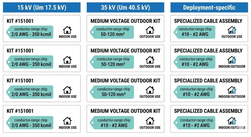
A spec-at-a-glance grid of the ten kit configurations grouped into 15 kV-class, 35 kV-class, and deployment-specific bands, each tagged with conductor range and indoor or outdoor suitability.
Underground Field Conditions That Change Your Pick
The same cable run can need a different termination depending on what the duct bank does to it. Underground environments add stressors that bench specifications ignore.
Condition-to-spec map
Underground condition
Effect on termination
Selection response
Moisture ingress / standing water
Water treeing, interface tracking
Wet-location sealed body + mastic seal at jacket entry
Duct-bank contamination
Surface tracking, reduced creepage
Outdoor shed profile even on near-surface entries
Thermal derating
Higher conductor temp, OD growth
Confirm OD at max operating temp, not ambient
Restricted jointing access
Incomplete recovery, rushed prep
Compact body; verify core-removal clearance
Moisture and contamination
Standing water in hand-holes and high-water-table duct banks is the dominant underground failure driver. A run that surfaces into a polluted pit can see contamination that effectively cuts usable creepage, so an outdoor shed profile is justified even where the cable barely emerges. In one recurring field pattern, terminations sealed only at the lug — but not at the jacket entry — let moisture migrate under the body within the first 12–18 months.
Thermal and dimensional shift
Conductor temperature on a loaded MV feeder commonly sits near 90 °C continuous, and the insulation OD grows as it heats: a cable measured at 20 °C ambient can gain ≈ 1–3% on outer diameter at 90 °C. If the cold-shrink body is already near the top of its recovery window at install, that Δ can drive the interface toward its limit — select with margin so the hot OD stays inside the band.
Access reality
Cold shrink’s torch-free recovery is its real underground advantage: in a flooded or confined pit where a flame is impractical, the spiral core still withdraws cleanly. But compact access cuts both ways — confirm enough radial and axial clearance to remove the core fully, since a partially recovered body is a latent fault. These execution details pair directly with the MV installation QC checklist.
Installation & Commissioning Realities
Kit selection sets the ceiling on reliability; installation decides whether you reach it. The dominant underground failure causes — partial discharge at the screen edge, moisture under the body, surface tracking — almost always trace back to preparation, not the kit.
Cable preparation and cutback discipline
Establish cutback dimensions from the kit instruction sheet, not from memory — the semicon cutback sets where the stress-control element lands.
Remove the outer jacket, metallic screen, and semiconductive screen to the marked lengths, keeping each transition square.
Clean the exposed insulation in one direction only, working away from the conductor toward the semicon edge, to avoid dragging carbon onto clean insulation.
Verify the measured insulation OD falls inside the recovery window before positioning the body.
The most common defect is residual semicon: a film of conductive material left on the insulation re-creates the field concentration the stress cone exists to relieve, and it is invisible at arm’s length.
Common field errors
Semicon residue or score marks on the insulation surface.
OD mismatch — a kit whose band the cable exceeds, leaving insufficient interface pressure.
Contamination of the silicone interface by hands, grit, or duct-bank water before recovery.
Post-install electrical verification
A VLF withstand test is typically applied at 0.1 Hz with a phase voltage on the order of ≈ 2–3 × U₀ for a defined duration (commonly 15–60 min) per the commissioning spec; pair it with partial-discharge measurement where the test set allows, since PD ≥ a few hundred pC at the termination flags a marginal interface before failure.
Test levels must follow the project commissioning standard — applicable references include the IEEE 400 family for field testing of shielded cable systems [VERIFY STANDARD: IEEE 400.2 VLF field test parameters] — and should never be improvised on site.
[Expert Insight] Three callback-killers underground
Wet pit floor: never set the de-cored body down before recovery.
Lug-only seal: always seal the jacket entry too, or moisture tracks under the body.
Skipped VLF/PD check: verify before energizing, not after the first fault.
Standards & Verification Before You Buy
A cold shrink kit is only as trustworthy as the test regime behind it. Its ratings should map to recognized references — otherwise a “35 kV” label is just a number on a box. The same procurement discipline applies across both transformer accessory and cable-accessory categories.
Standards that govern MV cold shrink terminations
IEC 60502-4 sits within the IEC 60502 series, whose overall scope spans extruded-insulation power cables and their accessories for rated voltages from 1 kV (Um = 1.2 kV) up to 30 kV (Um = 36 kV). Part 4 itself specifies the type-test requirements for accessories — indoor/outdoor terminations, joints, stop ends, and separable connectors — on cables rated from 6 kV (Um = 7.2 kV) up to 30 kV (Um = 36 kV), covering test arrangements plus dielectric/PD and AC withstand criteria (test methods in IEC 61442). Current edition: IEC 60502-4:2023.
IEEE 48 (current edition IEEE 48-2020) defines test procedures and requirements for AC terminations on shielded cable — laminated insulation 2.5 kV–765 kV or extruded insulation 2.5 kV–500 kV, excluding separable connectors (covered by IEEE 386) — framing the performance classes a termination is qualified to.
What to demand on the datasheet
A credible MV termination type-test report shows partial discharge ≤ a defined limit (commonly on the order of ≤ 5–10 pC) at a test voltage near ≈ 1.73 × U₀, measured at the qualifying class. A datasheet that omits both the PD level and the test voltage is incomplete, regardless of the headline voltage rating.
Cross-check the kit’s stated class against the cable’s rated voltage, confirm the OD window covers the as-laid cable, and require documentary test evidence. The cost of verification is trivial against an underground failure.
Spec-Match Your MV Underground Termination Kit
Every section above points to one decision: matching a specific kit to a specific cable. That comes down to five fields.
The 5 fields that define your kit
Voltage class — system rated voltage and Um (for example, 8.7/15 kV or 26/35 kV).
Conductor cross-section — in mm² (typical MV range 25–630 mm², up to 800 mm² on feeders).
Cable outer diameter — measured over the insulation, in mm, since this sets the recovery window.
Indoor or outdoor — where the cable surfaces, which decides the shed profile.
Quantity — including the correct leg count for three-core sets.
A measured OD beats a datasheet OD every time; a 1–2 mm difference is enough to move a marginal cable out of a kit’s band. With these five fields, an itemized cable accessories RFQ keeps quantities and accessories aligned across every line item. Share your specs, drawings, and target voltage class, and ZeeyiElec will respond with a matched kit configuration and quotation rather than a generic catalog list.
Frequently Asked Questions
What voltage classes do cold shrink cable termination kits cover for MV underground cables?
They typically span the 8.7/15 kV to 26/35 kV range, though the exact class follows the cable’s rated and maximum system voltage, so verify Um before ordering rather than relying on the nominal figure.
Why does cable outer diameter matter more than conductor size when selecting a kit?
The silicone body recovers only within a fixed diameter band, so the measured insulation OD — not the copper area — determines fit, and a 1–2 mm drift can move a cable outside the usable window.
How long does a cold shrink MV termination take to install?
A trained installer usually finishes one phase in roughly 20–40 minutes after preparation, but confined duct-bank access, weather, and three-core breakouts can extend that meaningfully in practice.
Is cold shrink better than heat shrink for underground duct banks?
Cold shrink is often preferred underground because it needs no flame and tolerates damp, confined access, though the right choice depends on environment, crew skill, and project economics rather than one being universally superior.
How long should a cold shrink termination last underground?
Properly selected and installed terminations commonly target the cable’s 25–40 year life, yet real longevity hinges on moisture sealing, contamination control, and installation quality more than the rated figure alone.
Can a single kit fit more than one cable diameter?
Each kit covers a defined OD band rather than one exact size, so it accommodates a small range of cables, but pushing beyond the stated limits risks incomplete recovery and should be avoided.
Do I need different kits for indoor and outdoor terminations?
Generally yes — outdoor variants add sheds and tracking-resistant surfaces for UV and pollution, so confirm the variant matches where the cable surfaces instead of assuming one kit serves both.
yoyo shi
Yoyo Shi writes for ZeeyiElec, focusing on medium-voltage accessories, transformer components, and cable accessory solutions. Her articles cover product applications, technical basics, and sourcing insights for global electrical industry buyers.





 English
 한국어
한국어 العربية
 Español
 हिन्दी
 தமிழ்
தமிழ் Deutsch (Sie)
 Français
 Português do Brasil
 Русский