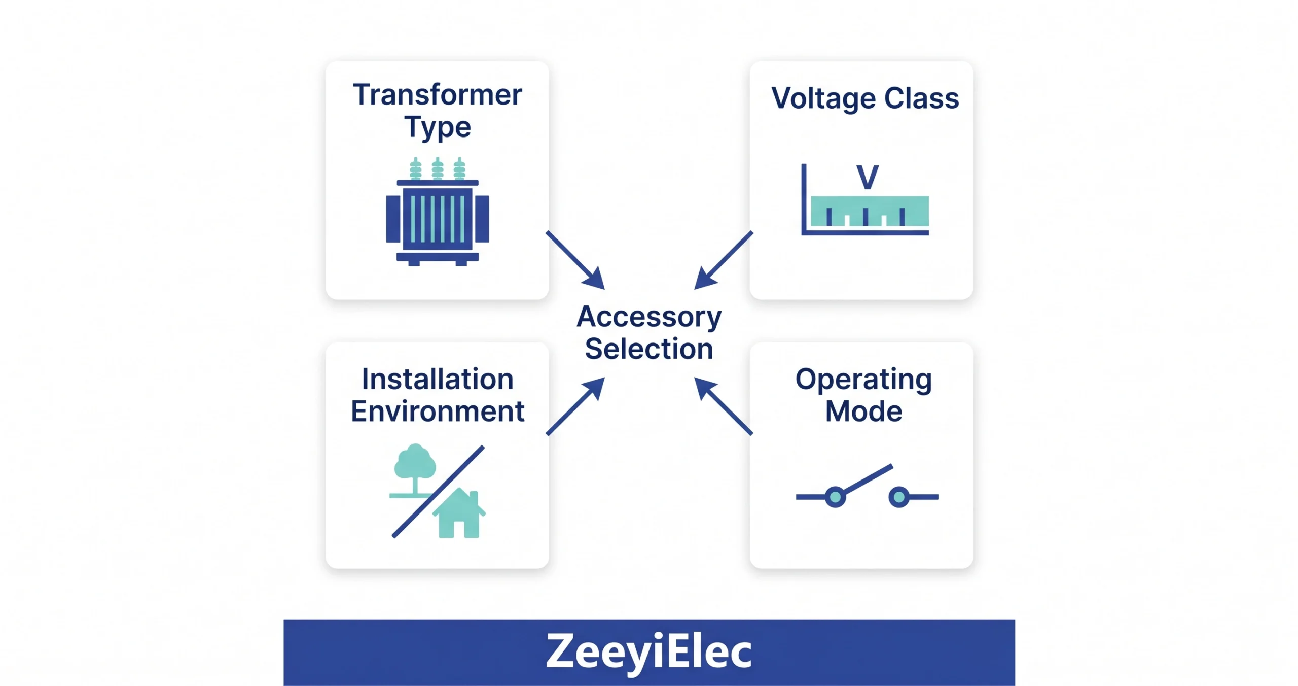
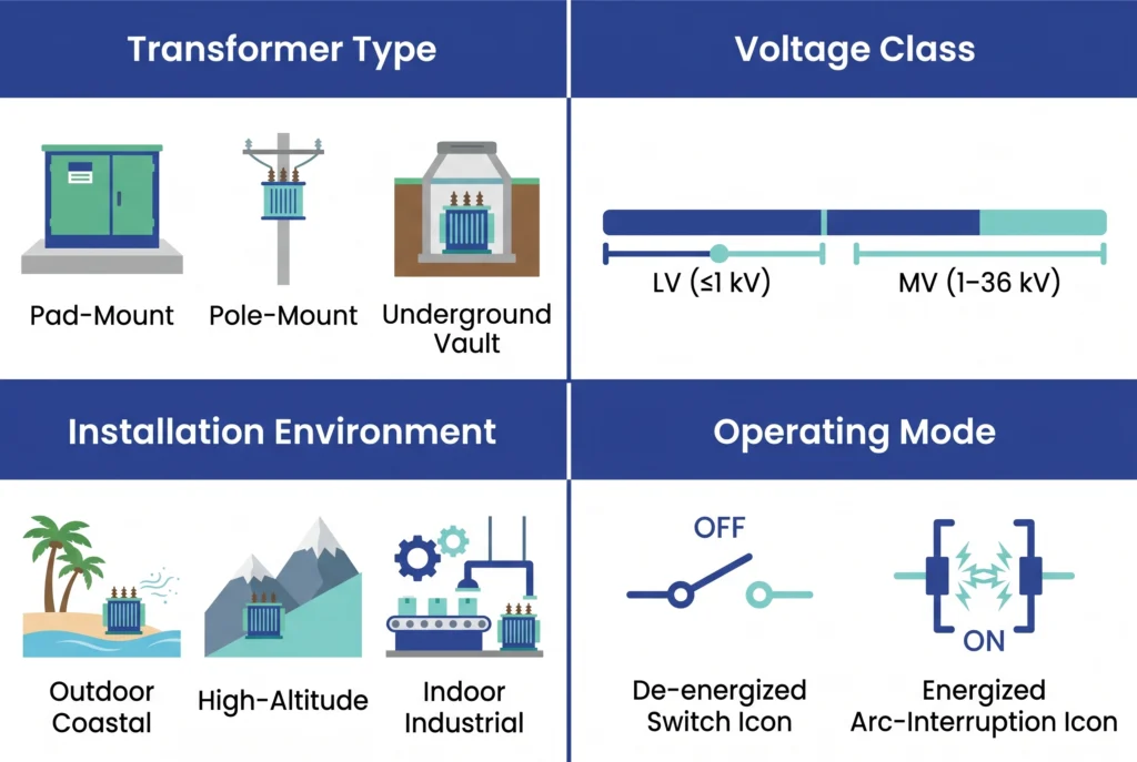
Transformer mounting configuration determines mechanical interface requirements and access geometry. A pad-mount transformer requires dead-front, hot-stick-operable accessories with specific tank-wall mounting patterns. A pole-mount transformer operates under mechanical loading from wind and ice, with maintenance access constrained to hot-stick reach. An underground vault installation adds space restriction and humidity management. Each type creates a different starting point before voltage class is considered.
Scenario Axis 2: Voltage Class
Voltage class defines the dielectric envelope: low-voltage accessories cover systems up to 1 kV, while medium-voltage accessories span 1–36 kV in distribution applications. The jump from a 15 kV class to a 25 kV class system involves different Basic Insulation Level (BIL) requirements, creepage distances, and insulation stress management architectures. Selecting a 15 kV rated bushing for a 25 kV system leaves a clearance deficit that thermal cycling and moisture ingress will exploit within 12–36 months under normal service conditions.
Scenario Axis 3: Installation Environment
Outdoor coastal installations require creepage distances significantly above IEC 60815 standard pollution levels for inland sites [VERIFY STANDARD: IEC 60815 clause for creepage distance selection by pollution severity class]. High-altitude sites above 1,000 m require derating of air-gap clearances due to reduced dielectric strength at lower air density. Indoor industrial environments introduce chemical contamination and temperature cycling that affect material selection between porcelain, epoxy, and polymer compounds.
Scenario Axis 4: Operating Mode
This axis is the most operationally consequential. Some accessories function only on a de-energized transformer; others must interrupt load current in service. Conflating these two modes is the single most common operating error in accessory selection — consequences range from accelerated contact erosion to internal arc faults within the transformer tank.
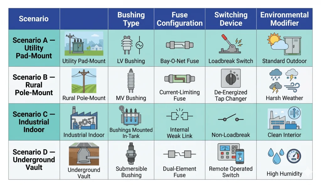
Application scenario matrix for transformer accessory selection: four axes (transformer type, voltage class, installation environment, operating mode) mapped to corresponding accessory families for distribution projects. (ZeeyiElec, 2026)
These four axes form the minimum specification framework. Every section that follows applies this framework to a specific accessory category.
Selecting Bushings by Application Scenario
A bushing failure is not a component replacement event — it is typically a transformer outage, with repair timelines measured in days and fault damage that can extend to windings and tank internals. Selection begins by establishing which side of the transformer is being served, then layering environmental and mechanical requirements over the electrical baseline.
LV Bushing Scenarios: Secondary Terminals and High-Current Industrial Applications
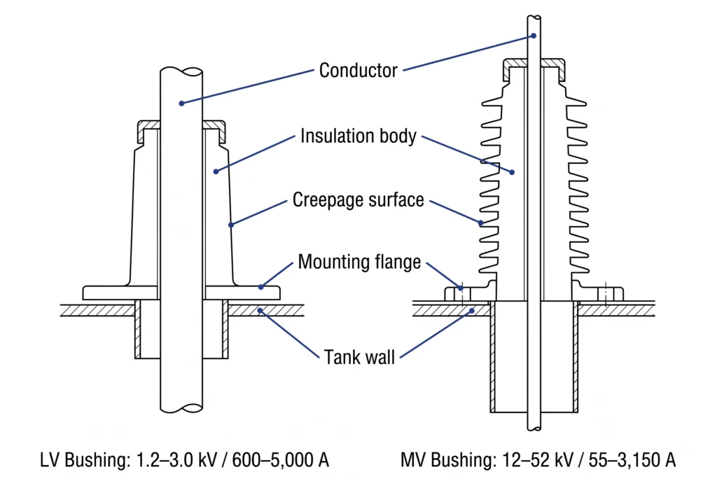
Low-voltage bushings serve the secondary side of distribution transformers at voltage classes of 1.2 kV to 3.0 kV. The defining electrical parameter on this side is current: LV bushings are specified from 600 A in smaller distribution units to 5,000 A and above in large industrial transformers. Material selection — HTN (High Temperature Nylon), porous resin, or porcelain — is driven by thermal cycling severity and the chemical environment at the installation site.
A recurring field pattern: secondary bushing failures in industrial installations most frequently trace to current rating underspecification rather than voltage breakdown. A bushing selected at nominal current with no margin for load growth or harmonic distortion will show accelerated thermal degradation at the terminal interface within 18–36 months of commissioning.
MV Bushing Scenarios: Primary HV Connection and Distribution Substation
Medium-voltage bushings operate on the primary side across voltage classes from 12 kV to 52 kV, with current ratings from 55 A to 3,150 A depending on transformer capacity. The standard system — ANSI porcelain, DIN porcelain, or epoxy resin — is determined by project geography and utility specification. ANSI configurations dominate North American utility projects; DIN standards apply across Europe, the Middle East, and parts of Asia; epoxy interfaces are increasingly specified where compact dimensions and moisture ingress resistance are prioritized. Selecting the wrong standard system produces a mechanically incompatible interface regardless of how well the electrical ratings match.
Bushing Well Inserts: When a Separable Interface Is Required
Bushing well inserts are specified where a separable, dead-front connection is required — the standard application being pad-mount transformers at 15 kV to 35 kV class with a 200 A continuous current rating. The well provides the tank-mounted insulation housing; the insert provides the replaceable, hot-stick-operable interface, allowing field personnel to disconnect and replace the insert without de-energizing the transformer or breaching the tank seal.
For projects combining bushing selection with a full accessory package, the transformer accessories overview provides the product family scope, and the medium voltage bushings series page covers ANSI, DIN, and epoxy configuration options with current and voltage class ranges.
Comparative cross-section of low-voltage (1.2–3.0 kV, 600–5,000 A) and medium-voltage (12–52 kV, 55–3,150 A) transformer bushings, showing conductor path, insulation body, flange mounting pattern, and creepage surface geometry. (ZeeyiElec, 2026)
[Expert Insight]
Creepage distance is not fixed by voltage class alone — pollution severity class (IEC 60815 light/medium/heavy/very heavy) can increase the required creepage by 40–80% above the base value for the same voltage rating.
Epoxy bushings offer superior moisture resistance but have lower thermal cycling tolerance than porcelain in applications with frequent load swings above 80% of rated current.
Always confirm the mounting flange standard (ANSI vs DIN hole pattern) against the transformer tank drawing before ordering — electrical ratings cannot compensate for a mechanical interface mismatch.
On export projects, request the transformer manufacturer’s bushing cutout dimensions in writing; nominal standard designations are interpreted differently across regional manufacturers.
Selecting Fuse Protection by Application Scenario
Transformer fuse selection is a coordination problem before it is a product selection problem. The objective is continuous protection across the full fault current spectrum — from sustained overloads at 1.5–2× rated current to bolted faults exceeding 50,000 A at the transformer terminals. No single fuse technology covers this entire range effectively, which is why distribution transformer protection schemes routinely deploy two fuse types in a coordinated sequence.
Bay-O-Net Fuse Scenarios: Pad-Mount Transformers and Field-Replaceable Protection
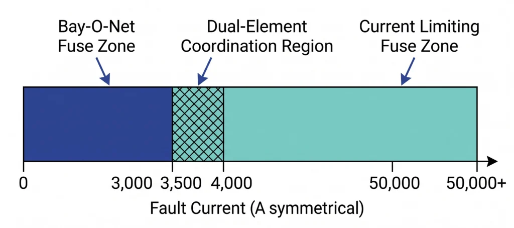
Bay-O-Net fuse assemblies are the primary protection interface on oil-filled pad-mount and submersible distribution transformers, designed to clear overloads and low-to-moderate fault currents up to approximately 3,500 A symmetrical. Beyond this threshold, the element cannot extinguish the arc reliably, risking assembly damage and transformer tank exposure.
The operational advantage is field replaceability: the fuse holder is hot-stick operable, allowing a lineman to restore service by replacing the fuse element without opening the transformer tank or de-energizing upstream equipment. Standard assemblies span 15 kV and 25 kV systems with a Basic Insulation Level of 150 kV full wave crest — parameters that must be matched to the primary system voltage before any current rating is evaluated.
Current Limiting Fuse Scenarios: High Fault Current Exposure and Backup Protection
Current limiting fuses are specified where available fault current at the transformer primary exceeds the interrupting capability of expulsion-type devices. A silver or silver-alloy fuse element within a silica sand-filled ceramic tube melts and the arc is quenched by the sand matrix, interrupting fault current within a half-cycle before it reaches its prospective peak.
Current limiting fuses for distribution applications are rated across voltage classes typically from 5.5 kV to 38 kV, with interrupting capacity reaching 50,000 A asymmetrical or higher. The fuse’s time-current characteristic must coordinate with upstream overcurrent devices: the current limiting fuse clears high-magnitude faults while the upstream relay or recloser handles sustained overloads below the fuse’s minimum interrupting current — typically 8–10× the fuse’s continuous current rating.
The applicable reference for current limiting fuse performance and test requirements is IEC 60282-1(High-voltage fuses — Part 1: Current-limiting fuses), which covers all high-voltage current-limiting fuse types for AC systems above 1,000 V — including back-up fuses used in distribution transformer protection. IEC 60282-2 governs expulsion-type fuses only and does not apply to current-limiting designs.
Dual-Element Coordination: When Both Are Required in Series
The most robust protection scheme combines both technologies: the Bay-O-Net handles overloads and moderate faults with field-replaceable convenience, while the current limiting fuse provides backup interruption for high-magnitude faults. This dual-element arrangement is standard practice on pad-mount units in urban distribution systems fed from substations with low source impedance.
A coordination failure observed repeatedly in field assessments: specifying a Bay-O-Net assembly on a feeder where available fault current routinely exceeds 5,000 A symmetrical. The assembly clears initial faults but shows progressive contact erosion after repeated operations — a pattern only visible during post-mortem inspection, by which point two or three fault events have already occurred.
Fault current spectrum for distribution transformer protection: Bay-O-Net fuse operating zone (0–3,500 A symmetrical) and current limiting fuse zone (3,500–50,000 A+), with dual-element coordination overlap region indicated. (ZeeyiElec, 2026)
Selecting Switching Devices by Application Scenario
The selection boundary between an off-circuit tap changer and a loadbreak switch is defined by one parameter: whether the transformer is energized at the moment the switching action occurs. This is not a design preference — it is a hard application boundary with direct consequences for equipment integrity and personnel safety.
Off-Circuit Tap Changer Scenarios: Voltage Regulation and Seasonal Load Variation
An off-circuit tap changer adjusts the transformer’s turns ratio by repositioning contacts across tapped winding sections. The mechanical action is straightforward; the constraint is absolute: switching must only occur after the transformer has been fully de-energized and isolated from both primary supply and secondary load.
Off-circuit tap changers are rated across three voltage classes — 15 kV, 25 kV, and 35 kV — with current ratings of 63 A and 125 A covering the majority of distribution transformer primary winding configurations. Tap positions are typically arranged in a ±2×2.5% or ±2×5% band, allowing output voltage correction across a ±5% to ±10% range depending on transformer design.
Application scenarios center on steady-state voltage correction: rural feeders with seasonal agricultural load cycles, long feeders where line impedance causes predictable voltage drop under peak load, and transformer commissioning where the initial tap position is set once and rarely adjusted thereafter.
A field case that appears consistently in rural network maintenance logs: a tap changer handle rotated during a brief upstream breaker opening that the operator assumed constituted full de-energization — without confirming that secondary load was also disconnected. The transformer was back-fed from the LV network through a running generator. Contact erosion was found during the next scheduled inspection, requiring tap changer replacement 14 months ahead of the expected service interval.
Loadbreak Switch Scenarios: Pad-Mount Sectionalizing and Loop-Feed Networks
A loadbreak switch makes or breaks rated load current with the transformer fully energized, providing switching capability for sectionalizing, loop-feed reconfiguration, and fault isolation without requiring upstream de-energization. The stored-energy quick-action mechanism is essential — contact separation must occur fast enough to extinguish the load arc before causing contact damage or dielectric breakdown in the surrounding oil.
Loadbreak switches are rated at 630 A continuous current across voltage classes of 15 kV, 25 kV, 38 kV, and 40.5 kV, covering both single-phase and three-phase oil-filled transformer configurations. The two-position design provides source selection or isolation; the four-position sectionalizing design supports loop-feed network topologies where the unit can be fed from either of two independent sources.
The most dangerous tap changer misoperation is procedural, not mechanical: back-feed from a secondary-connected generator or UPS during a planned outage is the most common cause of energized tap changer operation in field records.
Loadbreak switch contact life is rated in number of operations at full load current; confirm expected switching frequency against the manufacturer’s rated mechanical endurance — typically 200–500 operations at rated load for distribution class devices.
For loop-feed pad-mount installations, the four-position switch position labeling must be verified against the network single-line diagram before commissioning; mislabeled positions have caused inadvertent parallel operation of two sources with different voltage angles.
Matching Accessories to Four Common Deployment Scenarios
Selection logic applied in isolation produces individually correct components that may still constitute a poorly coordinated accessory package. The four deployment scenarios below synthesize the preceding criteria into complete accessory sets, incorporating the field conditions that modify theoretical specifications into practical procurement decisions.
Scenario A: Utility Pad-Mount Distribution Transformer (15/25 kV)
Primary side: medium-voltage bushings or 200 A bushing well inserts at 15 kV or 25 kV class, paired with a Bay-O-Net fuse assembly (150 kV BIL) for field-replaceable overload protection and a current limiting fuse in series where feeder fault current exceeds 3,500 A symmetrical. Switching: two-position or four-position loadbreak switch at 630 A. Secondary side: LV bushings rated from 1,000 A to 2,500 A continuous on 25–167 kVA single-phase units, scaling to 4,000 A and above on larger three-phase units. Environmental modifier: coastal installations require creepage distance upgrade on all MV components.
Scenario B: Pole-Mount Transformer in Rural Overhead Network
Porcelain MV bushings with extended creepage surfaces for outdoor pollution exposure. Voltage regulation via off-circuit tap changer at 15 kV or 25 kV class (63 A or 125 A) for seasonal voltage correction — tap position set during scheduled de-energized maintenance cycles only. High-altitude modifier: at 2,000 m, dielectric strength of air is reduced by approximately 15–20% relative to sea-level values, requiring uprated voltage class selection or confirmed manufacturer altitude derating data before procurement is finalized.
Scenario C: Industrial Substation Transformer (Indoor, High Fault Level)
Available fault current commonly reaches 20,000 A to 40,000 A symmetrical at primary terminals. Epoxy MV bushings (12–36 kV class) are preferred where chemical resistance and compact tank-wall footprint are required. Current limiting fuses are the primary protection specification; Bay-O-Net assemblies are typically absent — fault current levels exceed their reliable interrupting range, and the indoor installation removes their field-replaceability advantage.
Scenario D: Underground Vault Transformer (Space-Constrained, High Humidity)
Bushing well inserts at 200 A continuous, 15/25/35 kV class, are the standard primary interface: their compact separable design fits within vault clearance envelopes and provides a sealed, moisture-resistant interface that fixed bushing configurations cannot reliably maintain above 90% RH over a 20–30 year service life.
Fuse coordination follows Scenario A logic where fault current permits Bay-O-Net operation; current limiting fuses are substituted on low-impedance urban networks. Tap changers are off-circuit only — vault access restrictions make loadbreak switch operation the preferred method when the unit must be isolated for maintenance.
Accessory package mapping for four distribution transformer deployment scenarios: utility pad-mount (15/25 kV), rural pole-mount, industrial substation, and underground vault — showing bushing type, fuse configuration, switching device, and key environmental modifier per scenario. (ZeeyiElec, 2026)
For termination and jointing solutions where MV cable interfaces connect to transformer terminals, the cable accessories product range covers cold shrink and heat shrink options by voltage class and cable cross-section.
Five Specification Errors That Invalidate Accessory Selection
Correct accessory selection on paper does not guarantee correct performance in the field. The following five errors appear consistently across MV distribution projects — not as isolated incidents, but as repeating patterns when specification workflows skip one of the four scenario axes.
Error 1: Voltage Class Underspecification on MV Bushings
Specifying a 15 kV class bushing on a system where contingency conditions reach 17.5 kV or higher. Dielectric stress operates above design limits during voltage swells, initiating surface tracking at contamination sites within 6–18 months. Full flashover follows under the next sustained overvoltage event — typically a capacitor bank switching transient or a temporary overvoltage on unfaulted phases during a remote fault.
Error 2: Current Rating Underspecification on LV Bushings
A bushing rated at 600 A continuous operating at 580–620 A average with harmonic distortion factors of 15–25% sees effective thermal loading 10–18% above its steady-state design point. Terminal interface resistance increases progressively as the contact surface oxidizes under thermal cycling — measurable by infrared thermography within 18–30 months at these loading conditions.
Error 3: Fuse Coordination Sequence Reversal
Installing a current limiting fuse without a Bay-O-Net in a pad-mount application converts a routine overload event into a multi-hour outage requiring specialized tooling. Conversely, specifying a Bay-O-Net alone on a feeder with fault current above 3,500 A symmetrical risks incomplete arc extinction — escalating a recoverable overcurrent event into tank damage requiring oil sampling and internal inspection before re-energization.
Error 4: Off-Circuit Tap Changer Operated Under Load
Procurement documentation that does not explicitly label the tap changer as de-energized operation only creates conditions for operational misuse, particularly on export projects where operating procedures may be translated or summarized. A single operation under load causes contact surface erosion sufficient to increase resistance at the affected tap position; repeated operations introduce a high-resistance joint into the primary winding circuit with progressive thermal consequences for winding insulation.
Error 5: Environmental Class Mismatch on Insulation Materials
Standard inland-rated creepage distances and porcelain insulation on installations within 5–10 km of coastline or industrial contamination zones. Pollution layer accumulation followed by wetting produces surface leakage current and dry-band arcing that erodes shed surfaces over 24–48 months. Once shed erosion exceeds 15–20% of the effective creepage path, pollution withstand capability is no longer verifiable without laboratory testing.
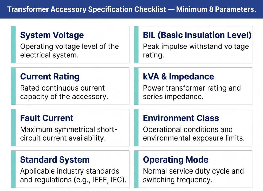
How to Build Your Transformer Accessory Specification Checklist
An accessory order that reaches manufacturing with incomplete specifications will either stall for clarification — adding 2–4 weeks to the procurement cycle — or proceed on assumed parameters that may not match site conditions. The checklist below consolidates the minimum parameter set required to specify each major accessory category without ambiguity.
System Voltage Class and Maximum System Voltage
Nominal voltage is insufficient; confirm the maximum continuous operating voltage the accessory must withstand under contingency conditions.
Basic Insulation Level (BIL)
Specified in kV peak; must match the transformer’s own BIL declaration, not just the voltage class label.
Current Rating
For LV bushings, confirm against peak load current including harmonic loading margin — not nameplate kVA alone.
Transformer kVA and Impedance
Required for fuse coordination calculations; impedance determines inrush current magnitude during energization.
Available Fault Current at Primary Terminals
In kA symmetrical; determines whether a Bay-O-Net, current limiting fuse, or dual-element protection scheme is required.
Installation Environment Classification
Indoor/outdoor, pollution severity, altitude above sea level, proximity to coast or industrial contamination sources.
Applicable Standard System
ANSI, IEC, or DIN; determines mechanical interface compatibility for bushings and mounting hardware.
Operating Mode
De-energized adjustment only (tap changer) or energized switching required (loadbreak switch); must be explicitly declared in procurement documentation.
For export projects, append: target market utility specification, shipping incoterms, and required test certification format. The full parameter framework is documented in the Transformer Accessories RFQ Checklist for engineer-level procurement use.
Eight-parameter specification checklist for transformer accessory procurement, covering system voltage, BIL, current rating, kVA and impedance, fault current, environment class, standard system, and operating mode — minimum inputs required before RFQ submission. (ZeeyiElec, 2026)
Ready to specify? Share your transformer datasheet and site environment details with ZeeyiElec’s engineering team for a technical selection review and RFQ response — typically within 24 hours for standard distribution accessory packages.
Frequently Asked Questions
What transformer accessories are required for a 15 kV pad-mount distribution transformer?
A standard 15 kV pad-mount unit typically requires medium-voltage bushings or 200 A bushing well inserts on the primary side, LV bushings rated to match secondary current output, a Bay-O-Net fuse assembly for field-replaceable overload protection, and a loadbreak switch for energized sectionalizing — exact ratings depend on kVA capacity and available fault current at the installation point.
How do I determine whether to use a Bay-O-Net fuse, a current limiting fuse, or both?
The primary decision gate is available fault current at the transformer terminals: Bay-O-Net fuses are appropriate where fault current does not exceed approximately 3,500 A symmetrical, current limiting fuses are required above this threshold, and dual-element coordination combines both in series for full-spectrum protection on urban or high-fault-current networks.
What is the operational difference between an off-circuit tap changer and a loadbreak switch?
An off-circuit tap changer adjusts the voltage ratio only when the transformer is completely de-energized and isolated from both primary and secondary circuits, while a loadbreak switch makes or breaks rated load current with the unit fully energized — the two devices serve entirely different operational functions and are not interchangeable.
How does installation altitude affect accessory selection?
At sites above 1,000 m, reduced air density lowers the dielectric strength of air gaps; at 2,000 m this reduction is approximately 15–20% relative to sea-level values, which may require selecting a higher voltage class rating or requesting manufacturer-confirmed altitude derating data before finalizing the specification.
When are bushing well inserts preferred over standard medium-voltage bushings?
Bushing well inserts are the preferred interface where a separable, dead-front, hot-stick-operable connection is required — typically pad-mount and underground vault applications at 15/25/35 kV class with 200 A continuous rating — providing safer maintenance access and a moisture-resistant sealed interface that fixed bushing designs cannot reliably sustain in confined or high-humidity environments.
What creepage distance specification applies to coastal transformer installations?
Coastal installations within 5–10 km of the sea require a higher pollution severity class than standard inland ratings, increasing required creepage distance by 40–80% above the base value for the same voltage class — the specific multiplier depends on site pollution severity classification, which should be confirmed with the utility or project engineer before bushing selection is finalized.
What causes current rating underspecification on LV transformer bushings?
The most common cause is selecting current rating against transformer nameplate kVA at unity power factor without accounting for harmonic loading from variable frequency drives or rectifier equipment — harmonic distortion factors of 15–25% can increase effective thermal loading by 10–18% above the steady-state design point, accelerating terminal interface degradation within 18–30 months.
yoyo shi
Yoyo Shi writes for ZeeyiElec, focusing on medium-voltage accessories, transformer components, and cable accessory solutions. Her articles cover product applications, technical basics, and sourcing insights for global electrical industry buyers.