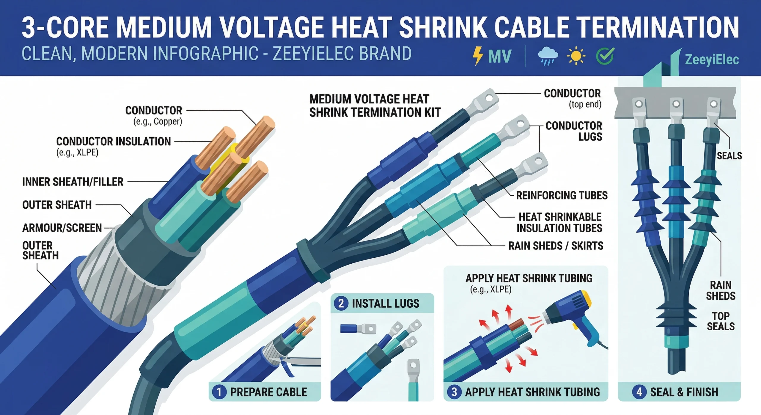
Heat shrink cable accessories are engineered interface components used to terminate, join, insulate, and protect power cables in LV and MV networks. Manufactured from cross-linked polymeric materials, these components are pre-expanded during production and will permanently recover their original, tighter diameter when heated, typically requiring localized installation temperatures between 110°C and 130°C.
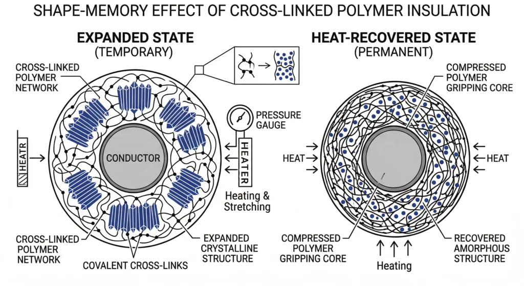
FIG-01:Cross-linked polymers are mechanically expanded during manufacturing and permanently shrink back to their original diameter when heated in the field.
Whether deployed as terminations, straight-through joints, or busbar insulation, their fundamental objective remains consistent: restoring insulation integrity and environmental sealing at vulnerable cable connection points. When the outer jacket and semi-conductive screens of a power cable are stripped away, the cable’s internal electrical stress field becomes highly concentrated at the cutback point. Without properly engineered cable accessories, this localized stress would quickly lead to partial discharge and eventual catastrophic breakdown.
The Principle of Polymeric Memory in MV Cable Terminations
In medium-voltage (MV) termination scenarios, the “memory” effect serves as the primary mechanism for establishing a high-pressure, void-free interface between the accessory and the cable insulation. During field commissioning, targeted heat triggers the polymer network to collapse around the prepared cable profile, driving internal stress-relief mastics into every microscopic crevice of the semi-con cutback. This active compression is vital for maintaining dielectric stability under the continuous thermal cycling of 15kV to 35kV distribution circuits.
Core Material Science and Component Structure
Cross-Linked Polymers and the “Memory” Effect
At the molecular level, the performance of these accessories is governed by a permanent three-dimensional carbon-carbon bond network created through irradiation or chemical cross-linking. This process transforms the base polyolefin from a thermoplastic into a “memory” elastomer. When heated above its crystalline melting point, the cross-links prevent the chains from flowing freely, allowing the material to be expanded and “frozen” into a temporary state. Upon re-heating during installation (110°C–130°C), the stored internal energy is released, forcing the polymer chains to return to their original, high-density configuration.
Stress Control Tubing and Mastics for 15kV/25kV Applications
Heat shrink systems mitigate concentrated electrical fields using specialized stress control tubing and mastics.
The stress control tubing achieves a relative permittivity (εr) typically ranging from 15 to 25. By overlaying this tube, the localized stress is kept ≤ 3.0 kV/mm to prevent insulation breakdown.
Anti-Tracking and Weather-Resistant Outer Layers
For outdoor use, specialized red or brown tubes provide resistance to surface tracking, electrical erosion, and ultraviolet (UV) radiation. The performance of these layers is evaluated using standardized tests such as those found on the IEC 60502-4 standard official page. For specific projects, engineers specify heat shrink cable accessories to support stable insulation performance.
Key Classifications and Voltage Applications
Voltage Class and Application Comparison Matrix
Category
Voltage Range
Configurations
Primary Field Application
LV Terminations & Joints
1 kV
Single/Multi-core
Secondary distribution
MV Terminations
10 kV to 35 kV
Indoor / Outdoor
Switchgear, transformers
MV Straight Joints
10 kV to 35 kV
Single/Three-Core
Underground trench splicing
Heat Shrink Straight-Through Joints for Underground Power
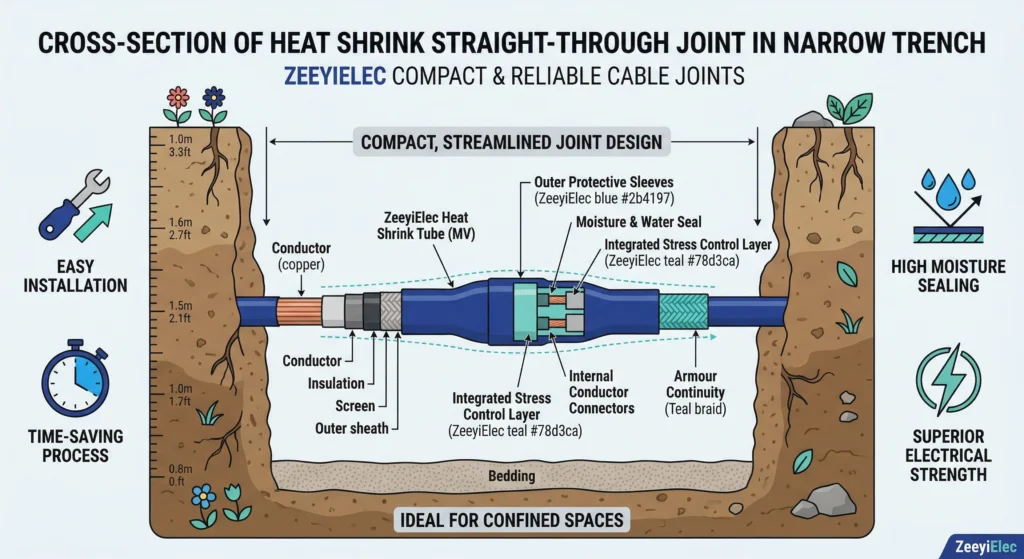
Heat shrink straight joints are engineered to fully reconstruct the cable’s multilayered architecture across a splice. These joints utilize heavy-wall, dual-rated tubing that combines a high-dielectric insulating inner wall with an integrated semi-conductive outer layer to seamlessly restore the cable’s electrical field profile. This robust design ensures that underground connections maintain total insulation integrity and moisture resistance, even when subjected to the high mechanical stress and thermal fluctuations common in direct-buried trench environments or flooded duct banks.
Field Application: Advantages and Practical Constraints
FIG-02:he compact profile of heat shrink straight joints provides a significant spatial advantage when splicing cables within narrow, congested underground duct banks.
Unlimited Shelf Life and Inventory Flexibility
Heat shrink tubes remain relaxed until heated, granting them a virtually unlimited shelf life compared to cold shrink alternatives. Provided storage temperatures remain ≤ 50°C, a 24 kV kit can sit in emergency inventory for years without degrading its recovery characteristics.
Conductor Range Adaptability for 70mm²-240mm² Cables
The high shrink ratio allows one kit to cover multiple conductor sizes (supporting up to 800 mm²), simplifying procurement logistics and reducing site delays.
The Constraint of Heat-Source Permitting (Hot Work)
The recovery process requires an active open flame (110°C–130°C). Engineers should use the cold shrink vs. heat shrink engineering selection framework to decide between technologies based on site constraints like “hot work” permit requirements.
Fundamental Installation Principles
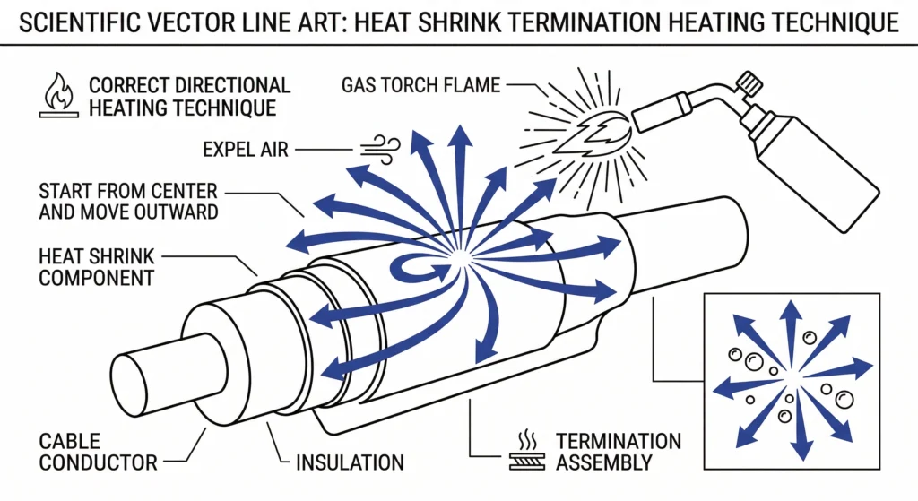
FIG-03:Applying heat systematically from the center outward actively expels trapped air from beneath the insulation tubing, preventing partial discharge voids.
Cable Preparation and Dimension Accuracy
Precision is mandatory. The semi-conductive screen must be cut squarely with a strict tolerance of ± 2 mm. Even a microscopic blade score can initiate electrical treeing and lead to catastrophic failure.
Even Heat Application and Shrink Direction
Installers must use a soft, moving flame to ensure uniform heating without localized scorching. The cardinal rule is directional shrinking: start from the center and move toward the ends, or start from one end and progress to the other. This systematic approach expels trapped air ahead of the shrink zone, preventing the formation of dielectric voids.
Post-Installation Visual Verification
Once the tubing has recovered, field engineers conduct a visual inspection to verify structural integrity. A properly installed heat shrink accessory should display a smooth, uniform profile without cold spots or blistering. A slight, even squeeze-out of internal environmental sealing mastic at the tubing ends confirms a watertight seal has been achieved.
Specification and Procurement Logic
Selecting the correct kit begins with precise electrical parameters.
Specifying 3-core 300 mm2 aluminum ensures the supplier provides correct breakout boots and lugs for load currents ≥ 600 A.
What is the typical temperature required to shrink cable accessories?
Heat shrink cable accessories typically require a targeted surface application temperature between 110°C and 130°C to activate the polymer’s memory effect fully. Installers must apply heat evenly using a specialized liquefied petroleum gas (LPG) torch to ensure proper recovery without localized material scorching.
How long do heat shrink cable accessories last in the field?
When engineered and installed correctly, they are built to match the 25 to 30-year expected service life of the distribution power cable. However, continuous thermal overloading or excessive UV exposure in highly polluted environments will proportionately degrade this operational lifespan.
Can heat shrink accessories be used on both copper and aluminum conductors?
Yes, the outer cross-linked tubing and internal mastics provide universal environmental sealing regardless of the cable’s conductor metal. Ensure that the internal mechanical lugs or crimp connectors supplied with the specific kit are explicitly rated for your chosen metal to prevent galvanic corrosion.
Do heat shrink cable accessories have a shelf life?
Because the structural polymers remain relaxed prior to heating, heat shrink components generally offer an unlimited shelf life when stored in dry environments with ambient temperatures ≤ 50°C. This stability makes them ideal for utilities maintaining long-term emergency replacement stocks.
What happens if air gets trapped during the heat shrink process?
Trapped air creates microscopic voids within the high-voltage insulation layer, which leads to localized partial discharge that progressively erodes the dielectric material. Field crews prevent this critical defect by systematically shrinking the tubing directionally from the center outward to smoothly expel all air.
What is the maximum voltage rating for standard heat shrink joints?
Standard heat shrink joints and terminations are widely deployed for medium voltage distribution networks spanning 10 kV up to 35 kV. For higher transmission-level voltages ≥ 69 kV, alternative technologies like pre-molded slip-on accessories are typically specified to handle the extreme electrical stress profiles.
yoyo shi
Yoyo Shi writes for ZeeyiElec, focusing on medium-voltage accessories, transformer components, and cable accessory solutions. Her articles cover product applications, technical basics, and sourcing insights for global electrical industry buyers.