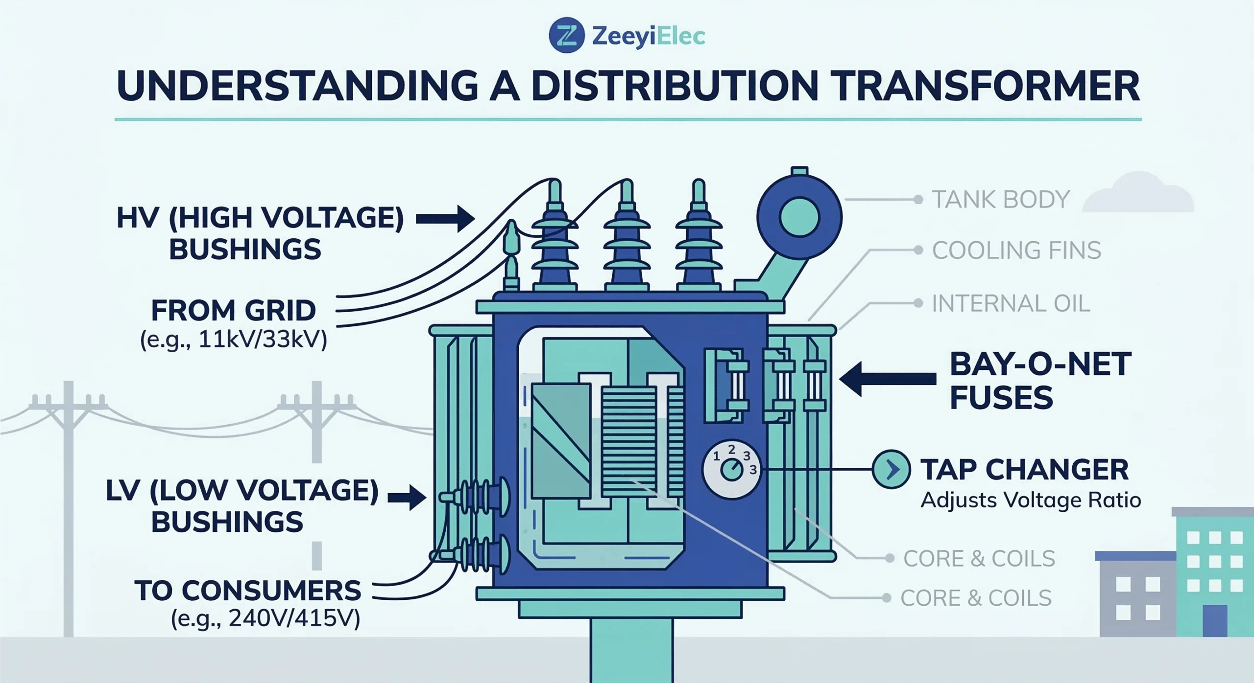
Transformer insulation is far more than a simple barrier; it is a coordinated engineering system designed to manage electric field stress, thermal energy, and mechanical forces over a service life of 25–40 years. Effective insulation architecture provides a reliable dielectric boundary between high-voltage conductors and the grounded transformer tank. In medium-voltage (MV) distribution systems, accessories like bushings, tap changers, and fuse assemblies serve as critical interface points where insulation integrity determines whether a grid operates reliably or fails prematurely.
Core Physics of Transformer Insulation Systems
At the transition points where a conductor passes through the transformer tank wall, the electric field gradient reaches its peak intensity. Effective insulation must account for the dielectric constant of different materials to prevent partial discharge (PD). For example, a typical 15 kV class bushing must maintain a Basic Insulation Level (BIL) of 95 kV or 110 kV. To manage these stresses, accessories utilize carefully calculated geometries to smooth electric field lines and prevent ionization.
The dielectric strength of the insulation system is governed by the peak electric field intensity (Emax), which must remain below the breakdown threshold of the insulating medium (typically 15–30 kV/mm for epoxy or high-grade transformer oil). The relationship between voltage (V) and the radius of the conductor (r) within a cylindrical bushing geometry can be approximated as:
E = V / [r * ln(R/r)]
Where R is the outer radius of the insulation barrier. If the ratio R/r is not optimized, the stress at the conductor surface will trigger ionization of the surrounding medium.
H3 Thermal Dynamics and Insulation Class
Insulation performance is inextricably linked to thermal management. Accessories are rated by their thermal class, defining the maximum continuous operating temperature. Standard transformer accessories are typically designed to operate within a 65°C temperature rise over ambient. Evidence from commissioning oil-immersed transformers suggests that even a 10°C rise above the rated insulation temperature can significantly reduce the mechanical strength of polymer components, leading to brittle failure under fault conditions. This makes the thermal stability of components like off-circuit tap changers and fuse holders vital during peak load.
[Expert Insight: Dielectric Integrity]
Stress Grading: Always verify that the semi-conductive layers in separable connectors are fully seated to prevent air gaps.
PD Testing: Factory Acceptance Testing (FAT) should confirm partial discharge levels <10 pC at 1.5 times the rated voltage.
Field Clearance: Maintain minimum phase-to-phase air clearances according to the specific BIL rating of the bushing.
Material Science of Secondary and Primary Bushings
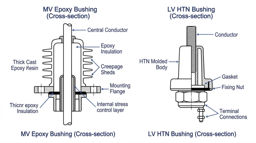
The selection of insulation materials balances dielectric strength, mechanical durability, and thermal stability. For distribution transformers, three primary materials dominate: High Temperature Nylon (HTN), Porous Resin/Epoxy, and Porcelain.
[FIG-01] Scientific illustration detailing the internal conductor paths and shed geometries of HTN vs. Epoxy insulation materials used in transformer secondary and primary interfaces.
H3 Material Performance Matrix
Selection must match environmental stressors; using standard resin in high-UV, coastal areas is a leading cause of premature tracking and surface erosion.
Parameter
High Temperature Nylon (HTN)
Epoxy / Resin
Porcelain (ANSI/DIN)
Voltage Class
LV (Up to 1.2 kV)
MV (12 kV – 52 kV)
MV (Up to 36 kV+)
Current Rating
600A – 5000A+
200A – 3150A
Up to 3150A
Thermal Stability
Excellent for high-current heat
Moderate; specialized required
High; immune to aging
Impact Resistance
High (Resists transit cracking)
Moderate
Low (Brittle; chips easily)
H3 Dielectric Integrity and Secondary Bushing Requirements
Low voltage bushings serve as the secondary interface, handling circuits up to 1.2 kV. HTN is preferred here because it maintains integrity at temperatures exceeding 120°C, essential for loads up to 5000A. Conversely, medium voltage bushings focus on voltage suppression. Epoxy interfaces are preferred for “dead-front” designs. According to IEC 60137, these must withstand power-frequency voltage tests at 2.2 times the rated voltage. [NEED AUTHORITY LINK SOURCE] — Suggested anchor: IEC 60137 Bushing Standards.
Stress Management and Dielectric Field Control
Dielectric field control prevents localized electrical stress from exceeding the ionization threshold of the insulating medium. When a conductor passes through the grounded tank, field lines concentrate at transition points; unmanaged, this leads to partial discharge and eventual insulation failure.
H3 Dielectric Interfaces and Shielding Logic
The interface between internal oil and external accessories is the most vulnerable point. Bushing wells and inserts utilize a coordinated shielding approach. The 200A insert incorporates an internal semi-conductive shield that encapsulates the contact area, creating a “Faraday cage” effect that eliminates internal corona discharge.
In high-stress applications, the electric field intensity (E) at any point is proportional to the voltage gradient. To maintain dielectric stability, the design must satisfy the following condition:
Eapplied < (Ebreakdown / SF)
Where Ebreakdown is the dielectric strength of the epoxy or porcelain (typically 15–20 kV/mm) and SF is a safety factor, usually ≥ 2.5 for utility-grade equipment. For a 25 kV class system with a 150 kV BIL, the insulation thickness and shed geometry are specifically calculated to keep surface creepage stress below 0.5 kV/mm.
H3 Geometry and Creepage Distance
Accessories like medium voltage bushings feature a “shedded” design to increase creepage distance—the shortest path along the surface between conductive parts. Sheds provide “dry zones” during rain and break up tracking paths. Matching the shed profile to local pollution levels (measured in mm/kV) is a critical step for preventing flashover in coastal zones.
Selection Logic for Medium-Voltage Insulation Components
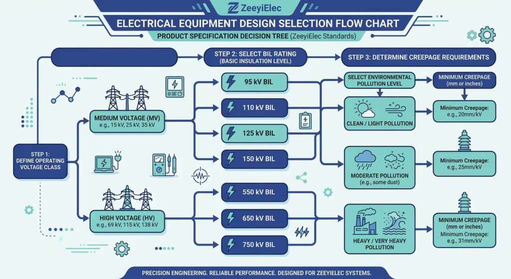
Selecting MV insulation requires aligning the electrical environment with the mechanical capability of the accessory. Incomplete specifications account for 40% of accessory mismatches. For distribution transformers rated 10–35 kV, engineers must cross-reference 15–25 parameters before purchase.
[FIG-02] Decision matrix for specifying medium-voltage accessories, accounting for system voltage class, required BIL, and environmental pollution levels.
H3 Identifying Voltage Class and BIL Requirements
The Basic Insulation Level (BIL) measures surge-withstand capability. A 15 kV system typically requires 95 kV or 110 kV BIL. When sourcing cold shrink cable accessories, voltage class must match exactly; 8.7/15kV kits cannot be interchanged with 26/35kV systems due to differing dielectric stress control layers.
H3 Environmental Matching
Pollution Levels: Coastal sites require higher creepage to prevent tracking from salt spray.
Indoor vs. Outdoor: Heat shrink cable accessories for outdoor use include extra sheds to increase the creepage path.
Material: Porcelain offers superior UV resistance, while epoxy is favored for compact “dead-front” designs.
Safety Architecture in Overcurrent Protection
Safety relies on a coordinated protection architecture. Without rapid interruption, fault energy would vaporize oil and char solid dielectrics. Protection is achieved by pairing two distinct fuse technologies.
H3 Coordination Logic
Low-level faults are managed by Bay-O-Net fuse assemblies, which clear faults up to approximately 3,500 amperes. High-magnitude faults exceeding this are handled by current limiting fuses, which clear within a half-cycle.
The coordination logic follows a specific “Total Clear” curve where the Bay-O-Net (Ilow) and the Current Limiting Fuse (Ihigh) intersect. To prevent insulation damage, the total energy let-through (I²t) must be kept below the transformer’s through-fault withstand capability:
I²tfuse < I²twithstand
[Expert Insight: Protection Maintenance] * Hot-Stick Safety: Always use a hot-stick when operating Bay-O-Net holders to maintain dead-front safety distances. * Oil Quality: Check for carbonization in the fuse holder after a low-level fault clearing. * Coordination: Ensure backup current-limiting fuses are sized to avoid nuisance blowing during transformer inrush.
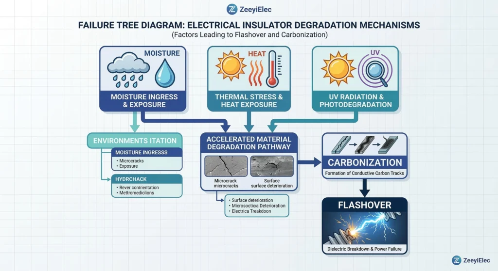
Field Performance and Environmental Degradation
Industry data shows that 15–25% of transformer outages trace back to accessory malfunction. Accessories serve as the interface between the sealed tank and the volatile atmosphere.
[FIG-03] Technical diagnostic workflow illustrating the progression from environmental stressors like moisture ingress to dielectric breakdown and accessory failure.
H3 Altitude and Moisture Factors
Altitude: Above 1000m, reduced air density decreases cooling and dielectric strength.
Moisture: Water is the primary catalyst for failure. It enters via aging gaskets or when operating off-circuit tap changers.
Vbd ≈ k / √W
Where W is the water content in ppm. If water content rises from 10 ppm to 40 ppm, the dielectric strength can drop by more than 50%, risking internal flashover.
Engineering Support and RFQ Technical Verification
Efficient procurement requires precise technical alignment. Missing data in an RFQ can extend a two-week cycle into six weeks. At ZeeyiElec, we eliminate these bottlenecks through:
Model Matching: Cross-referencing 15–25 parameters for 10–35 kV transformers.
Technical Consulting: Guidance on material selection for high altitude or salt spray.
Export Support: Professional handling of test certificates and documentation.
What is the standard BIL for a 15 kV transformer accessory?
Most 15 kV class accessories are specified with a Basic Insulation Level (BIL) of 95 kV or 110 kV to provide a sufficient safety margin against transient voltage surges.
When should epoxy bushings be chosen over porcelain?
Epoxy bushings are ideal for dead-front, compact transformer designs where submersible or screened connections are required, whereas porcelain remains the standard for high-UV and corrosive environments.
Why does high altitude require accessory derating?
At altitudes above 1000 meters, the thinner air has lower dielectric strength and reduced heat dissipation capacity, necessitating a larger creepage distance or a reduction in rated voltage.
How does a current limiting fuse protect transformer insulation?
A current limiting fuse interrupts high-magnitude fault currents within a half-cycle, drastically reducing the thermal and mechanical energy (I²t) that would otherwise compromise dielectric integrity.
What is the effect of moisture on transformer oil dielectric strength?
Increasing moisture content drastically reduces the dielectric breakdown voltage of insulating oil, significantly increasing the risk of internal flashover across accessory interfaces.
Can cold shrink and heat shrink terminations be used interchangeably?
Selection depends on the environment; cold shrink offers constant radial pressure and faster installation, while heat shrink is often preferred for mechanical ruggedness in industrial applications.
yoyo shi
Yoyo Shi writes for ZeeyiElec, focusing on medium-voltage accessories, transformer components, and cable accessory solutions. Her articles cover product applications, technical basics, and sourcing insights for global electrical industry buyers.