The Vital Organs of a Transformer: Why Accessories Matter
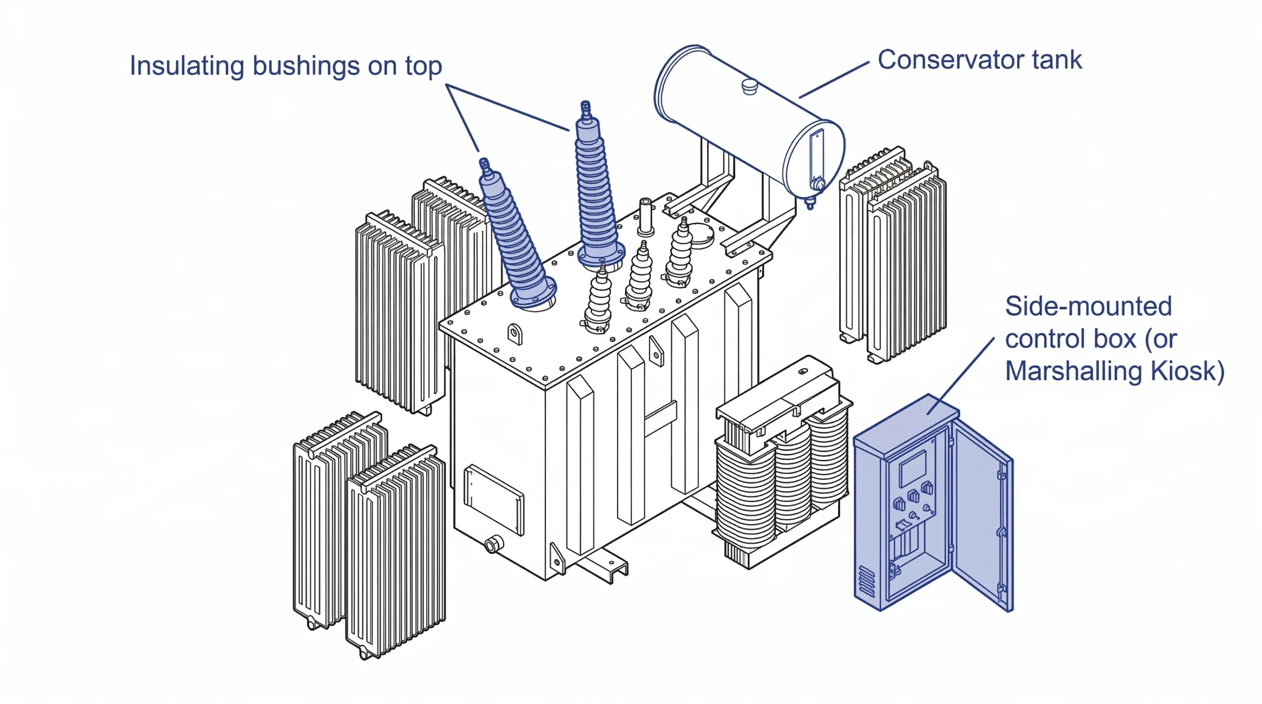
At its core, a transformer is an elegant application of electromagnetic induction, consisting primarily of an iron core and copper or aluminum windings. However, translating this simple physics principle into a reliable piece of grid infrastructure capable of operating for 30 years requires a sophisticated ecosystem of specialized components. These transformer accessories are not merely add-ons; they are the vital organs that protect the core, manage thermal loads, and maintain the precise dielectric boundaries between high-voltage electricity and the external environment.
The fundamental challenge in transformer design is managing electrical stress and thermal degradation. While the active part (the core and coil assembly) performs the actual voltage transformation, it is entirely dependent on external components to function safely. For instance, the transition from internal windings submerged in insulating oil to external power lines relies on precisely engineered dielectric interfaces. Without these components, the transformer cannot connect to the grid without initiating a catastrophic ground fault to the steel tank.
Furthermore, accessories serve as the primary diagnostic interface for maintenance personnel. In an environment where internal temperatures can routinely exceed 90 °C and transient overvoltages are common, components like pressure relief valves, breathers, and gas-actuated relays provide real-time condition monitoring. They act as the first line of defense against internal faults, transforming a static piece of electrical equipment into an active, monitored asset.
When specifying components for a new installation or planning a maintenance cycle, it is imperative to understand that the failure of a single accessory—whether a degraded seal or a malfunctioning temperature gauge—can compromise the entire transformer. Securing top-tier transformer accessories is the most effective way to prevent unplanned outages and costly emergency repairs.
[Expert Insight]
Over 40% of premature transformer failures originate not in the core windings, but from compromised or poorly maintained external accessories.
A single degraded flange gasket can introduce enough atmospheric moisture to halve the dielectric strength of the insulating oil within a matter of months.
Upgrading legacy analog accessories to sensor-ready digital equivalents is often the most cost-effective life-extension strategy for aging grid assets.
Insulating Bushings: The Dielectric Interface
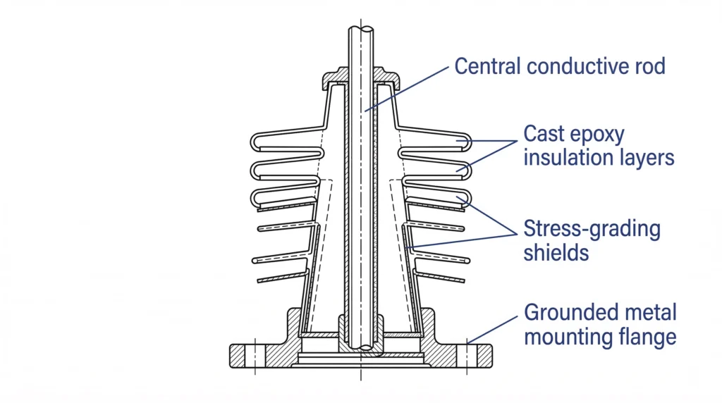
A transformer bushing is the primary dielectric bridge that allows the live conductor to exit the grounded transformer tank without initiating a devastating phase-to-ground short circuit. Internally, a central conductive rod carries the load current, while the surrounding insulation system—traditionally porcelain or, increasingly, advanced cast epoxy resin—manages the intense electrical field gradients.
Figure 01:The internal stress-grading architecture of a cast epoxy medium-voltage bushing.
The baseline metric for bushing reliability is its dielectric strength and external creepage distance. According to [NEED AUTHORITY LINK SOURCE: IEC 60137 for insulated bushings above 1000 V], these components must be precision-engineered to withstand continuous operating voltages and transient lightning impulses without surface tracking.
For outdoor installations in heavily polluted environments, engineers must specify a creepage distance of ≥ 31 mm/kV. This structural geometry ensures that surface leakage currents remain below safety thresholds (typically < 10 μA), preventing complete surface flashover even when the bushing housing is coated in coastal salt spray or conductive industrial dust.
Low-Voltage vs. Medium-Voltage Bushings
The physical architecture of a bushing scales dramatically with voltage. Low-voltage variants (typically rated 1 kV to 3.6 kV) rely primarily on the bulk dielectric properties of the porcelain or resin body. However, medium-voltage bushings operating at 12 kV, 24 kV, or 36 kV demand active stress control. These higher-voltage components often incorporate internal grading shields or precise geometrical profiling. This careful shaping evenly distributes the electrical stress across the insulation volume, preventing localized partial discharge (PD) that would progressively eat away at the insulating material over years of operation.
Common Bushing Failure Modes and Prevention
From a field maintenance perspective, catastrophic bushing failures are rarely caused by spontaneous dielectric breakdown; they are typically the culmination of slow mechanical degradation. When a mounting flange gasket loses its elasticity due to years of thermal cycling, moisture can ingress into the main tank. An increase in insulating oil moisture content from 10 ppm to just 30 ppm drastically reduces the dielectric withstand capability of the entire system. Consequently, routine visual inspections for micro-leaks at the mounting flange, combined with periodic infrared thermography to detect high-resistance hot spots on the terminal connections, are mandatory practices for grid reliability.
Tap Changers: Mastering Voltage Regulation
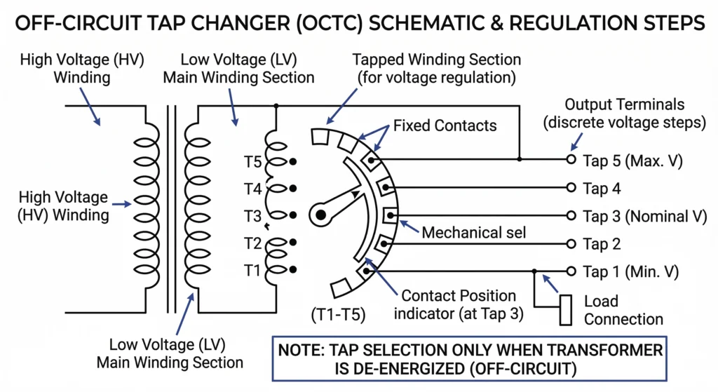
A transformer’s ability to deliver a stable secondary voltage, despite continuous fluctuations in the primary supply grid, relies entirely on its tap changer mechanism. By physically altering the number of active turns in the high-voltage winding, this accessory changes the transformer’s voltage ratio. Selecting the correct tap changer type is a foundational engineering decision that dictates the equipment’s operational flexibility and its long-term maintenance schedule.
Figure 02:Standard winding configurations and selector positions for a de-energized tap changer.
Off-Circuit Tap Changers (DETC)
A De-Energized Tap Changer (DETC) is the standard solution for distribution networks requiring infrequent, seasonal voltage adjustments. As the name implies, the transformer must be completely isolated from the power grid before a field technician manually adjusts the tap setting. Attempting to switch a DETC while the transformer is energized will almost certainly result in a catastrophic internal arc and severe equipment destruction.
Standard off-circuit tap changers typically offer voltage regulation in discrete steps, such as ±2.5% or ±5% of the nominal voltage. To prevent localized overheating under full load, the contact resistance across the selector switch must measure ≤ 500 μΩ during routine maintenance diagnostics.
On-Load Tap Changers (OLTC)
In environments with dynamic load profiles, such as industrial facilities or renewable energy grid integrations, an On-Load Tap Changer (OLTC) is generally specified. An OLTC performs the complex mechanical sequence of changing the winding ratio without interrupting the load current. This is achieved using a specialized diverter switch and transition resistors that briefly absorb the circulating current during the split-second transfer, which usually completes in 40 to 70 milliseconds.
Because the diverter switch actively arcs during normal operation, it is housed in a dedicated oil compartment to prevent the main transformer tank from becoming contaminated with carbon byproducts. Maintenance crews must regularly test this dedicated OLTC oil for dielectric breakdown and schedule internal contact replacements after approximately 50,000 to 100,000 switching operations, depending heavily on the historical load current and specific manufacturer guidelines.
[Expert Insight]
Routine DGA (Dissolved Gas Analysis) on the main transformer tank cannot diagnose OLTC diverter switch wear; the OLTC compartment requires entirely independent oil sampling.
Operating a DETC mechanism that hasn’t moved in a decade requires extreme caution; contact coking can cause severe resistance spikes if not properly exercised before re-energization.
Modern vacuum-type diverter switches drastically reduce oil carbonization compared to legacy oil-arcing designs, extending maintenance intervals by up to 300%.
Pressure Relief and Internal Fault Protection
When a high-energy internal fault occurs within a transformer—such as a winding-to-winding short circuit or a major dielectric breakdown—the resulting electrical arc instantaneously vaporizes the surrounding insulating oil. This phase change from liquid to gas generates a massive and nearly instantaneous pressure spike. If this rapid gas expansion is not immediately vented, the immense hydrostatic force can rupture the steel transformer tank, resulting in catastrophic failure, fire, and severe environmental contamination. Protecting the structural integrity of the asset relies entirely on purpose-built mechanical accessories designed to activate within milliseconds.
Pressure Relief Valves (PRV)
The primary defense against catastrophic overpressure is the rapid pressure rise valve (PRV). Typically mounted on the transformer cover or upper tank wall, a PRV is a spring-loaded mechanical device engineered to open immediately when the internal pressure exceeds a predetermined threshold.
For standard distribution and medium-voltage power transformers, these precision valves are factory-calibrated to operate at a specific differential pressure, commonly set between 35 kPa and 70 kPa (approximately 5 to 10 psi). Upon activation, the heavy-duty spring compresses, lifting the sealing disk to rapidly vent the explosive mixture of vaporized oil and combustible gas. Once the internal pressure equalizes, the valve automatically reseats to prevent further oil loss and mitigate external moisture ingress.
Gas Actuated (Buchholz) Relays
While a PRV mitigates the effects of a high-energy explosive fault, it provides zero warning for slow-developing, low-energy faults. This is where the Buchholz relay—the foundational diagnostic accessory for conservator-equipped transformers—becomes essential. Installed in the pipework connecting the main tank to the conservator, this dual-element relay physically captures bubbles of fault gas as they rise through the oil.
If minor localized overheating or partial discharge begins degrading the paper insulation, small volumes of gas (primarily hydrogen and methane) will slowly accumulate in the upper chamber of the relay, eventually displacing enough oil to trigger a low-level alarm switch (typically when 200 to 300 cm³ of gas has collected). Conversely, if a sudden, violent fault occurs, the resulting surge of oil toward the conservator will physically strike the lower baffle plate in the relay, instantaneously triggering a trip signal to isolate the transformer from the grid before the PRV is forced to operate.
Moisture Control and Condition Monitoring in the Field
In real-world operating environments, a transformer is constantly subjected to dynamic thermal cycling. As the internal insulating oil heats up under peak electrical loads, it expands; as the load drops or ambient weather conditions cool, the oil contracts. This thermal “breathing” creates a vacuum effect that actively draws atmospheric air into the conservator tank. If left unchecked, the moisture and physical contaminants in this drawn air will rapidly degrade both the insulating oil and the solid paper windings.
Figure 03:The color degradation spectrum of silica gel indicating active to saturated moisture levels.
Dehydrating Breathers and Silica Gel
To prevent atmospheric moisture from contaminating the dielectric fluid, incoming air is forced through a dehydrating breather. This critical external accessory typically features a lower oil cup that traps airborne dust particles, followed by a transparent cylindrical chamber filled with silica gel crystals. From a field maintenance perspective, breathers provide the most immediate visual indicator of a transformer’s sealing integrity and environmental stress.
Active silica gel is treated with a moisture indicator that changes color as it becomes saturated—traditionally from deep blue to light pink, or in modern heavy-metal-free gels, from orange to clear. Maintenance crews must proactively replace or thermally reactivate the silica gel when approximately 60% to 75% of the column has changed color. Allowing saturated air into the tank can increase the oil’s water content, which must strictly remain ≤ 15 ppm for medium-voltage applications to prevent an accelerated drop in dielectric withstand capability.
Oil Level and Winding Temperature Indicators
Beyond moisture control, field operators rely on external analog and digital gauges to continuously monitor internal thermodynamic health without de-energizing the equipment. Magnetic Oil Level Indicators (MOLI) translate the vertical movement of a float inside the conservator tank into a dial reading on the exterior. This magnetic coupling is a vital design feature, ensuring that the gauge mechanism itself does not create a mechanical leak path through the steel tank wall.
Similarly, Winding Temperature Indicators (WTI) and Oil Temperature Indicators (OTI) are essential for preventing accelerated thermal degradation.
These accessories utilize fluid-filled capillary tubes connected to sensing bulbs positioned in the top-oil pockets. A WTI goes a step further by using a heating coil proportional to the load current to simulate the actual winding hot-spot temperature. For standard Class A insulation, field engineers configure these gauges to trigger auxiliary cooling fans at approximately 65 °C and initiate a mandatory breaker trip if the hot-spot temperature exceeds 105 °C, thereby preserving the equipment’s expected operational lifespan.
Specifying ZeeyiElec Accessories for Extended Service Life
When evaluating suppliers for critical grid infrastructure, procurement teams must look beyond initial unit costs and focus on total lifecycle reliability. Specifying premium components directly translates to extended service life, often pushing the operational lifespan of a transformer from 20 years to well over 30 years.
Precision Manufacturing and APG Technology
The core of modern dielectric reliability lies in advanced manufacturing. ZeeyiElec utilizes state-of-the-art Automatic Pressure Gelation (APG) technology for its epoxy resin insulation systems. This precision casting process eliminates microscopic voids, consistently achieving partial discharge (PD) levels of ≤ 5 pC at 1.2 × Ur (rated voltage). Whether you are sourcing components for a 24 kV distribution transformer or integrating cable accessories into a broader medium-voltage network, insisting on APG-manufactured insulation is the most reliable way to prevent long-term dielectric breakdown.
Partner with ZeeyiElec for Your Component Needs
From OEM-customized bushings to high-performance tap changers and fault relays, ZeeyiElec provides a comprehensive portfolio of components engineered to meet stringent global standards. Our rigorous factory acceptance testing ensures every component is mechanically and electrically verified before it reaches your facility. Ready to upgrade your manufacturing supply chain or source critical replacement parts for field maintenance? Explore our full catalog of solutions and contact our engineering team today to discuss your specific technical requirements.
Frequently Asked Questions
What is the function of a rapid pressure rise relay?
A rapid pressure rise relay continuously monitors the rate of pressure change within the insulating oil, initiating a breaker trip in milliseconds if a sudden spike occurs (e.g., >10 kPa/s) due to an internal arcing fault. This rapid response isolates the transformer from the grid faster than standard electrical relays, actively preventing tank rupture.
How does moisture affect transformer insulation?
Moisture drastically lowers the dielectric breakdown voltage of the insulating oil and acts as a catalyst for the chemical degradation (depolymerization) of the paper windings. In medium-voltage systems, allowing water content to exceed 15-20 ppm can accelerate the aging rate of the cellulose insulation by more than 50%, leading to premature equipment failure.
Can off-circuit tap changers be motorized?
Yes, while off-circuit tap changers (DETC) require the transformer to be completely de-energized before switching, the physical switching mechanism itself can be motorized for remote operation. However, rigorous interlocking systems must be integrated to guarantee the main circuit breakers are open before the motor drive can engage.
What is the purpose of an oil conservator?
The oil conservator acts as an expansion reservoir positioned above the main transformer tank, safely accommodating the fluctuating volume of the insulating oil as it heats and cools under load. This design ensures the active core remains entirely submerged at all times while significantly restricting the surface area of oil exposed to atmospheric contaminants.
Why do transformer bushings use capacitance grading?
Capacitance grading, achieved by embedding conductive foil layers within the bushing’s insulation, actively forces a uniform distribution of electrical stress radially and axially across the component. Without this internal grading, electrical stress would concentrate heavily near the grounded mounting flange, inevitably triggering destructive partial discharge in medium and high-voltage applications.
What maintenance does a Buchholz relay require?
Routine maintenance for a Buchholz relay primarily involves visually inspecting the viewing window for collected gas and verifying the mechanical operation of the internal floats during scheduled outages. If gas is discovered, technicians must safely extract a sample through the built-in petcock to determine whether it is harmless trapped air or combustible fault gas requiring immediate DGA analysis.
yoyo shi
Yoyo Shi writes for ZeeyiElec, focusing on medium-voltage accessories, transformer components, and cable accessory solutions. Her articles cover product applications, technical basics, and sourcing insights for global electrical industry buyers.