The Core Principle: Understanding Electromagnetic Induction
A transformer is a static electrical device that transfers energy between two or more circuits through electromagnetic induction. Without any physical or conductive connection between the source and the load, it utilizes alternating magnetic flux generated by a primary winding to induce an electromotive force (EMF) in a secondary winding. This fundamental mechanism allows power networks to step voltage up for highly efficient long-distance transmission or step it down for safe local distribution.
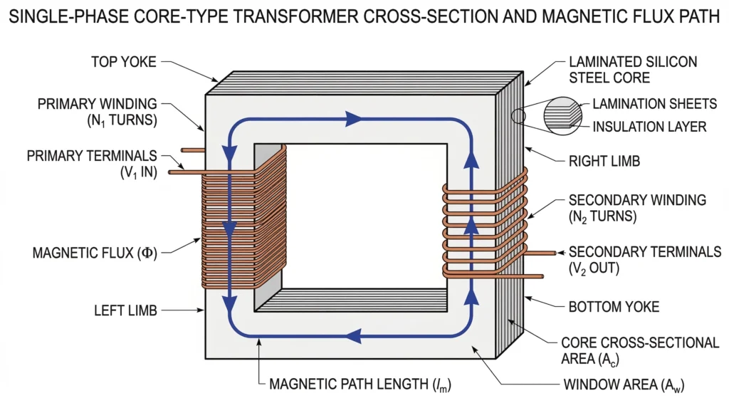
Figure 01:An alternating current in the primary winding generates a time-varying magnetic flux that permeates the steel core and links to the secondary winding.
Faraday’s Law and Magnetic Flux
The operation of every distribution and power transformer is governed by Faraday’s Law of Induction. When an alternating voltage is applied to the primary winding, it drives an alternating current that generates a time-varying magnetic field. This field is concentrated and guided by a highly permeable magnetic core, linking it almost entirely to the secondary winding.
To maintain efficient energy transfer and minimize core losses, modern distribution transformers are structurally engineered to operate at a specific magnetic flux density. In typical grain-oriented silicon steel cores, this operating flux density ranges from 1.5 to 1.7 Tesla (T) under normal load conditions, carefully kept below the core’s magnetic saturation point.
The relationship between these variables is defined by the universal EMF equation for a transformer winding: E = 4.44 × f × N × Φmax. In this formula, E is the induced root-mean-square (RMS) voltage, f is the grid operating frequency, N represents the number of winding turns, and Φmax is the peak magnetic flux measured in Webers.
The Role of Alternating Current (AC) in Transformers
Electromagnetic induction strictly requires a constantly changing magnetic field to induce a secondary voltage. Consequently, transformers only function with alternating current (AC) waveforms. In standard utility power grids operating at continuous frequencies of 50 Hz or 60 Hz, the direction of the alternating current—and therefore the polarity of the internal magnetic flux—reverses 100 or 120 times per second, providing the constant rate of change required for induction.
If a direct current (DC) voltage is mistakenly applied to a transformer, the operational frequency is effectively 0 Hz. The magnetic field expands once during energization and then becomes completely static. Because the rate of flux change (dΦ/dt) drops to zero, no secondary voltage is induced. More critically, without the opposing induced voltage (back-EMF) to impede the flow, the primary current is restricted only by the pure DC resistance of the copper or aluminum winding. In medium-voltage distribution transformers, this DC resistance is often extremely low—frequently < 0.5 Ω. Applying DC therefore results in massive, instantaneous overcurrent and rapid thermal degradation of the winding insulation.
Structural Anatomy: Core, Windings, and Insulation
A transformer’s ability to sustain electromagnetic induction over a decades-long lifespan relies entirely on its structural anatomy. The three fundamental building blocks—the magnetic core, the conductive windings, and the dielectric insulation system—must operate in thermal, electrical, and mechanical harmony.
Magnetic Core Construction and Eddy Currents
The core serves as the controlled pathway for the magnetic field. It is constructed from cold-rolled grain-oriented (CRGO) silicon steel, a material chosen for its exceptionally high relative magnetic permeability (μr). However, an alternating magnetic field induces unintended circulating currents within the core itself, known as eddy currents, which generate waste heat. To mitigate this, the core is never a solid metal block; instead, it is assembled from ultra-thin steel laminations, typically ranging from 0.23 mm to 0.35 mm in thickness, with each layer coated in a microscopic insulating film.
Primary and Secondary Winding Configurations
The primary and secondary coils are wound concentrically around the core limbs. Conductors are drawn from high-purity electrolytic copper or electrical-grade aluminum. In standard distribution transformers, the low-voltage (LV) winding is positioned physically closest to the grounded steel core to minimize the required dielectric clearance. The high-voltage (HV) winding is then wound concentrically outside the LV winding.
To safely bridge the gap between these internal active windings and the external overhead or underground grid, reliable transformer accessories must be specified and installed on the tank exterior. From a field operations standpoint, ensuring tight mechanical clamping of these internal windings during manufacturing is vital; loose coils are highly susceptible to shifting during transport or buckling under severe electromechanical short-circuit forces.
Dielectric Materials and Insulation Mediums
The primary cause of premature transformer failure is not mechanical wear, but dielectric breakdown. To prevent internal arcing, the bare winding conductors are tightly wrapped in specialized Kraft paper. In liquid-filled distribution units, this solid cellulose insulation works in tandem with a liquid dielectric medium—typically highly refined mineral oil or synthetic ester fluids. The fluid permeates the porous paper, significantly increasing its dielectric strength while simultaneously absorbing and dissipating core heat.
Under [VERIFY STANDARD: IEC 60076-1] guidelines governing power transformers, standard liquid-immersed cellulose insulation systems are generally assigned a Class A thermal rating. This classification safely permits a maximum continuous operating hotspot temperature of 105°C. Exceeding this specific thermal threshold accelerates the chemical breakdown of the paper, permanently compromising the unit’s insulation integrity.
Expert Insight: Field Diagnostics for Insulation
Monitor Dissolved Gases: Implement routine Dissolved Gas Analysis (DGA) on dielectric fluids to detect early hydrocarbon markers of cellulose breakdown before physical failure occurs.
Track Thermal Limits: Continuously log operating temperatures; remember that sustained operation just 10°C above the 105°C Class A threshold reduces paper insulation lifespan by roughly 50%.
Verify Mechanical Integrity: Ensure tight mechanical clamping of windings during Factory Acceptance Testing (FAT) to prevent dangerous shifting under severe electromechanical short-circuit forces.
Transformer Ratios and Step-Up/Step-Down Logic
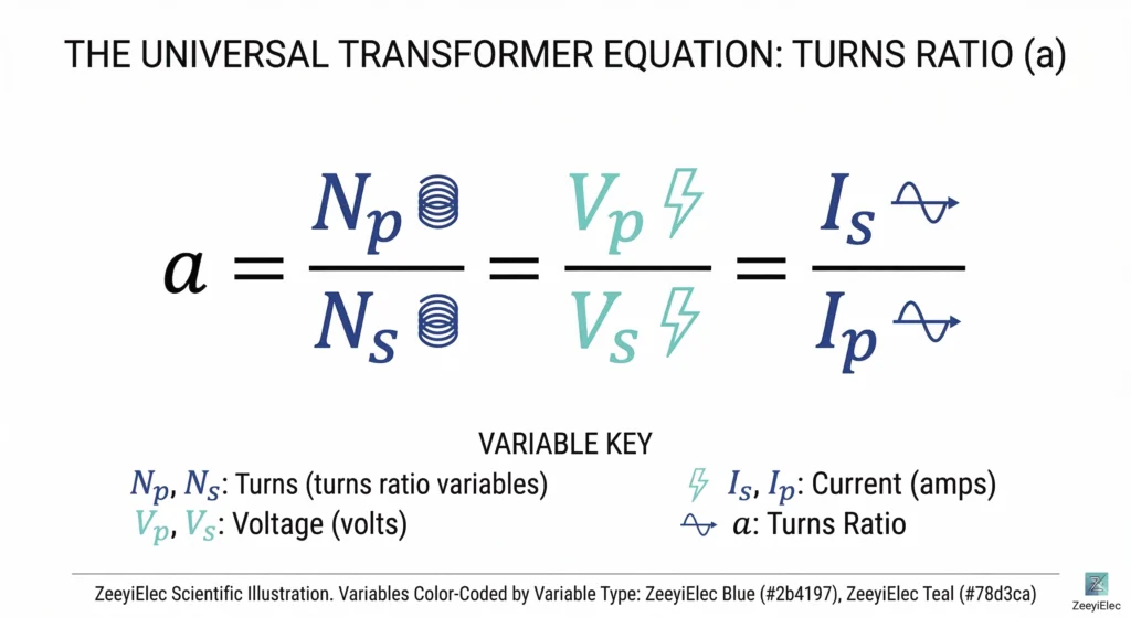
Figure 02:The turns ratio mathematically dictates the proportional relationship between the primary and secondary voltage and current, maintaining the balance of power.
Calculating the Turns Ratio
The core mathematical principle governing any transformer is the turns ratio, often denoted as a. It dictates the exact proportional relationship between the primary and secondary sides of the circuit. The formula is expressed as: a = Np / Ns = Vp / Vs = Is / Ip, where N represents the number of winding turns, V is voltage, and I is current. Assuming an ideal transformer where input power equals output power (neglecting minor core and copper losses), voltage scales directly with the number of winding turns, while current scales inversely to maintain the balance of power (P = V × I).
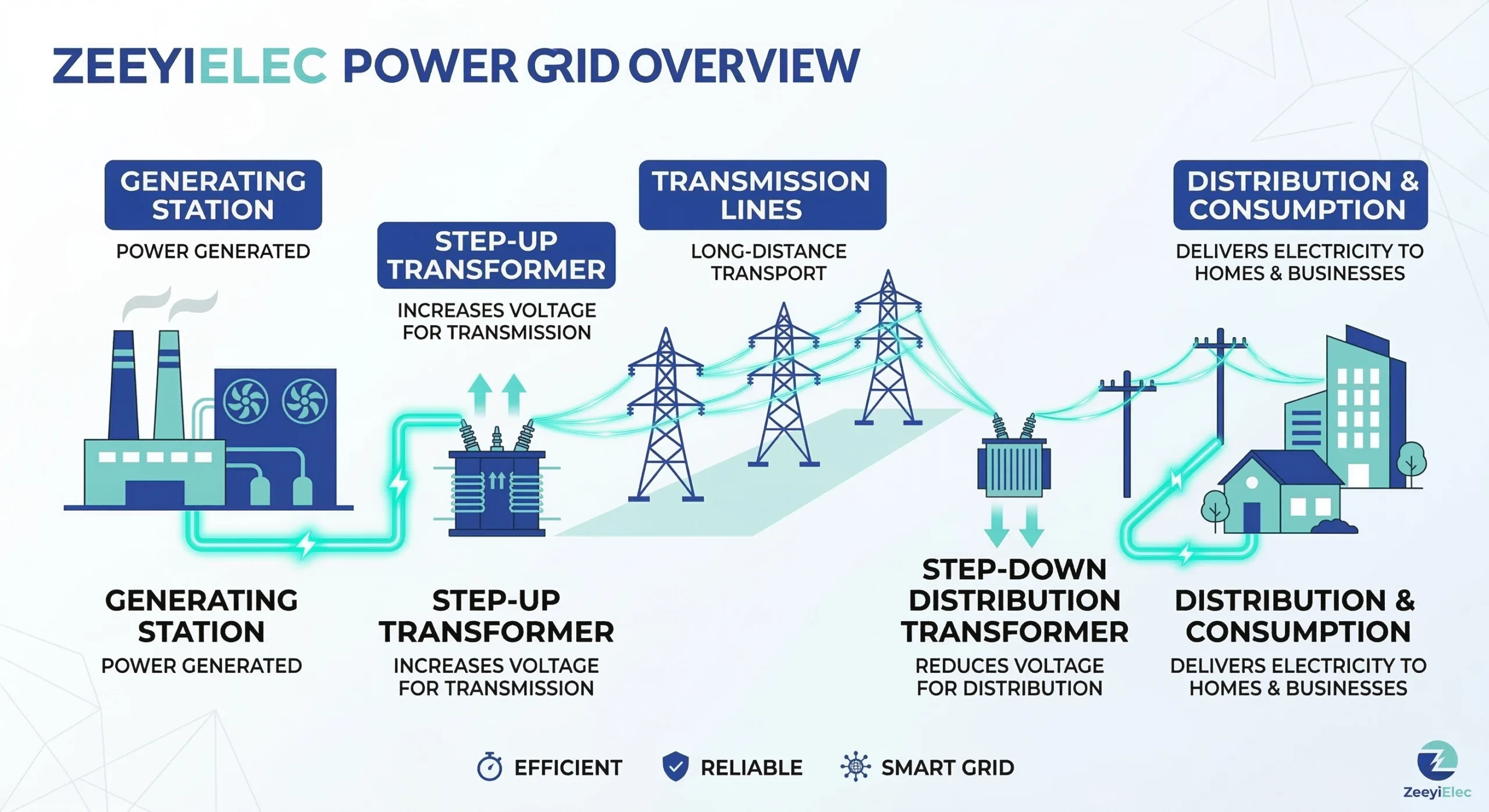
Step-Up Transformers in Power Generation
At centralized power generation facilities, turbines generate electricity at relatively low voltages, typically ranging from 11 kV to 25 kV. If utilities attempted to transmit this power over hundreds of kilometers at such low voltages, the required current would be massive.
Because conductor resistive heat losses are calculated as Ploss = I2R, doubling the current quadruples the energy lost as heat. To mitigate this, step-up transformers are installed directly at the generating station to elevate the voltage to transmission levels, such as 230 kV or 400 kV. In accordance with global transmission frameworks such as IEC 60038 standard voltages, stepping the voltage up by a factor of 20 reduces the corresponding current by a factor of 20, slicing transmission line thermal losses by a factor of 400. This is the fundamental reason alternating current grids dominate global power distribution.
Step-Down Transformers in Distribution Networks
Once high-voltage power reaches a municipal or industrial area, it must be reduced to safe, usable levels. Step-down transformers at primary electrical substations first reduce the extreme transmission voltages down to medium-voltage distribution levels, typically between 15 kV and 35 kV.
From the substation, the power is routed through local distribution networks to smaller pole-mounted or pad-mounted distribution transformers. These final step-down units reduce the medium voltage to low-voltage utilization levels. For example, a standard residential step-down transformer might take a 13.8 kV primary feed and convert it to a 240/120 V secondary output, making it safe for household appliances and commercial equipment.
Critical Interface Components: Bushings and Tap Changers
While the internal core and windings handle the physics of electromagnetic induction, transferring that power safely in and out of a grounded steel transformer tank requires specialized interface components. These external accessories act as critical structural barriers, preventing catastrophic ground faults while maintaining a hermetic seal for the internal dielectric fluid.
High-Voltage and Low-Voltage Bushings
A bushing is an insulated pass-through device that allows an energized conductor to penetrate the transformer enclosure. Without it, the high-voltage current would instantly arc to the grounded steel tank. To safely manage the electrical stress field at this grounded boundary, medium voltage transformer bushings are engineered with specific exterior shed profiles to maximize creepage distance. They are typically manufactured from high-grade wet-process porcelain or cast epoxy resin.
Bushings are specified strictly by their operational voltage class and continuous current carrying capacity. For example, a primary bushing on a distribution unit might be rated for 24 kV and 250 A, requiring a tested Basic Insulation Level (BIL) of ≥ 125 kV to successfully withstand transient lightning impulses. Conversely, secondary low-voltage bushings must manage massive current outputs—often rated between 600 A and 3150 A—necessitating thick, highly conductive copper studs and high-temperature nylon (HTN) or epoxy insulation.
Voltage Regulation via Tap Changers
Because incoming grid voltages constantly fluctuate based on regional load demand and transmission distances, a transformer must be able to fine-tune its output voltage. This is achieved mechanically by altering the active turns ratio of the primary winding using a tap changer. By selectively adding or removing physical turns from the circuit, the secondary voltage can be precisely raised or lowered.
In standard distribution networks, this structural adjustment is predominantly handled by off-circuit tap changers. As the name dictates, these mechanical switches must only be operated when the transformer is completely de-energized. A typical off-circuit tap changer provides a regulation range of ±5%, usually divided into five discrete operating positions (e.g., +5%, +2.5%, 0, -2.5%, -5%). Attempting to rotate an off-circuit mechanism while the transformer is carrying a live 15 kV load will draw an immediate internal arc, vaporizing the copper contacts and critically damaging the internal insulation.
Expert Insight: Specifying Interface Components
Match Creepage to Environment: Always calculate required bushing creepage distance based on specific site contamination levels, aiming for ≥ 31 mm/kV in heavy industrial or coastal zones.
Prevent Thermal Warping: Specify High-Temperature Nylon (HTN) or advanced epoxy for secondary LV bushings handling continuous loads >1000 A to ensure structural stability over time.
Enforce Safety Interlocks: Require mechanical padlocking mechanisms on off-circuit tap changers to physically prevent operators from adjusting voltage ratios while the transformer is energized.
From Theory to Grid Reality: Field Conditions in Power Transmission
The theoretical efficiency of electromagnetic induction is thoroughly tested in controlled factory environments, but grid deployment introduces chaotic, real-world variables. Field-installed distribution transformers must constantly battle thermal gradients, environmental contamination, and unpredictable electrical transients that threaten their insulation integrity over a multi-decade operational lifespan.
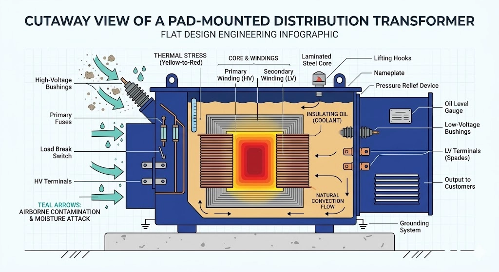
Figure 03:Field-installed distribution transformers endure severe thermal gradients, moisture ingress, and external contamination that continuously degrade insulation life.
Thermal Stress and Cooling Mechanisms
In the field, peak load demand frequently coincides with extreme summer weather, pushing the transformer to its extreme thermal limits. If the ambient temperature reaches 40°C, standard natural convection cooling mechanisms struggle to dissipate the heavy heat generated by core eddy currents and winding resistance. As a universal engineering rule, operating the unit just 10°C above its rated insulation hotspot limit (typically 105°C for standard Class A cellulose) accelerates the chemical degradation of the paper, effectively reducing the remaining lifespan of the insulation by roughly 50%.
Environmental Contamination and Dielectric Wear
External interfaces, including cable accessories connecting to the bushings, face relentless environmental bombardment. In coastal regions or heavy industrial zones, airborne salt, chemical exhaust, or metallic dust settles on exterior sheds. When combined with light moisture or morning fog, this contamination layer becomes highly conductive, leading to surface tracking and dry-band arcing. To combat this in field applications, site engineers must specify external accessories with extended creepage distances—often ≥ 31 mm/kV for heavily polluted environments—to prevent external flashovers from the energized terminal to the grounded steel tank.
Transient Overvoltages and Grid Realities
The theoretical perfect alternating current sine wave rarely exists in an active distribution grid. Transformers are routinely subjected to transient overvoltages caused by direct atmospheric lightning strikes or the operation of downstream switching equipment. These high-frequency surges travel rapidly down the transmission lines and strike the primary windings with extreme, microsecond voltage spikes. To survive these severe field conditions, the transformer’s internal insulation system must be meticulously designed to withstand its tested Basic Insulation Level (BIL), relying on external surge arresters to safely shunt extreme transients to ground before they puncture the delicate dielectric paper.
In active distribution networks, external faults are inevitable. When a downstream cable is severed or a lightning strike triggers a flashover, the resulting surge of fault current will rapidly destroy the transformer’s internal windings if not interrupted. Protecting this critical asset requires a coordinated sequence of switching and fusing accessories.
Overload vs. Fault Protection Sequencing
Field engineers must differentiate between mild, temporary thermal overloads and catastrophic short circuits. A field-installed pad-mounted transformer might safely tolerate a 120% load demand for several hours during peak summer usage. However, a bolted fault generating massive electro-dynamic forces can warp the core, severely deform the copper windings, and rupture the tank within milliseconds if protection devices fail to operate.
Component Coordination Logic
Effective protection utilizes a two-stage sequential strategy. First, externally serviceable bay-o-net fuse assemblies are deployed to manage secondary faults and mild overloads, typically clearing currents up to approximately 3,500 A. Second, for high-magnitude primary faults that exceed this threshold, partial-range current limiting fuses (CLFs) operate in series. These backup fuses are engineered to interrupt massive short-circuit currents—often ≥ 50,000 A—within a single half-cycle, limiting the peak let-through energy. Furthermore, for safe network sectionalizing and routine maintenance isolation, loadbreak switches are integrated, allowing field operators to safely make or break the rated 200 A or 630 A load current without de-energizing the entire upstream feeder.
Specifying the Right Accessories for Your Grid Project
Selecting the correct protection components prevents premature equipment failure and catastrophic network outages. ZeeyiElec provides comprehensive engineering support to match loadbreak switches, fusing solutions, and termination accessories to your specific project requirements. Contact our technical team today to streamline your RFQ process and secure reliable transformer accessories engineered for the most demanding distribution grid realities.
Frequently Asked Questions
How efficient is a standard distribution transformer?
Modern distribution transformers typically operate at 98% to 99.5% efficiency, though actual field efficiency depends heavily on core material grade, loading cycles, and operating temperature. While highly efficient, the remaining 1–2% of lost energy manifests as heat that cooling systems must dissipate to prevent insulation degradation.
What is the typical lifespan of a power transformer?
The design lifespan of a power transformer generally ranges from 25 to 40 years, assuming stable grid conditions and proper maintenance. However, cumulative thermal stress, frequent short-circuit events, or severe environmental contamination can significantly reduce this operational life if accessories and insulation are not monitored.
Can a transformer operate on direct current (DC)?
No, a standard transformer cannot operate on DC because electromagnetic induction requires a constantly changing magnetic field, which is only produced by an alternating current (AC) waveform. Applying continuous DC voltage to a transformer winding creates a static magnetic field, resulting in zero voltage transfer and potentially causing the primary winding to overheat and fail.
How does temperature affect transformer capacity?
Transformer capacity is strictly thermally limited; operating approximately 10°C above the unit’s rated insulation temperature threshold reduces the insulation’s lifespan by 50%. Consequently, a transformer operating in a 40°C ambient environment without enhanced cooling cannot safely carry the same continuous load as it would in a 20°C environment.
What determines the physical size of a transformer?
A transformer’s physical size is primarily dictated by its power rating (kVA or MVA) and its voltage class, which govern the required cross-sectional area of the core, conductor size, and dielectric clearance distances. Higher voltage classes demand significantly thicker insulation and larger bushing interfaces, increasing overall dimensions even if the power rating remains moderate.
Why do transformers hum or buzz during operation?
Transformers produce a characteristic 100 Hz or 120 Hz hum due to magnetostriction, a phenomenon where the silicon steel core laminations physically expand and contract as the alternating magnetic field reverses direction. The intensity of this noise varies based on core design, operating voltage, and load levels, but it is a normal acoustic byproduct of electromagnetic induction.
yoyo shi
Yoyo Shi writes for ZeeyiElec, focusing on medium-voltage accessories, transformer components, and cable accessory solutions. Her articles cover product applications, technical basics, and sourcing insights for global electrical industry buyers.