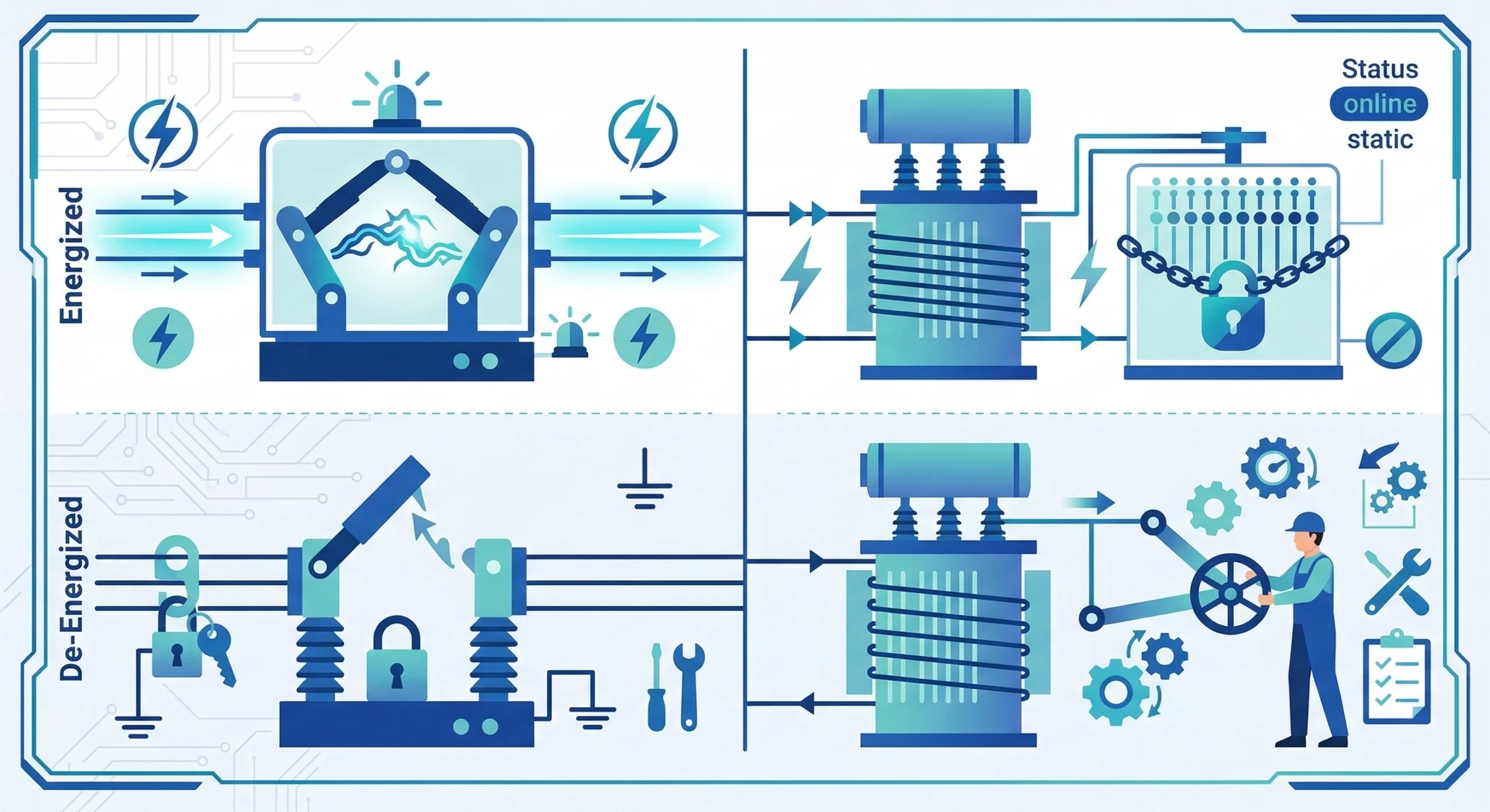
The Application Boundary: Energized vs. De-Energized Operation
A loadbreak switch interrupts current while the transformer stays energized. An off-circuit tap changer adjusts voltage ratio only after the transformer is de-energized. This single distinction—energized versus de-energized operation—defines the application boundary between these two devices. Both components appear on distribution transformers. Both involve a switching action, and both mount externally with handles or motor operators.
These surface similarities cause confusion among engineers specifying and field personnel operating them. The confusion carries real consequences. Operating an off-circuit tap changer under load damages contacts and risks internal transformer faults. Specifying a loadbreak switch where voltage adjustment is needed leaves the core problem unsolved.
To establish a reliable baseline for distribution components, engineers generally reference guidelines such as [VERIFY STANDARD: IEEE C57.12.00] for liquid-immersed transformers. A standard pad-mounted loadbreak switch is typically engineered to interrupt 630 A of continuous load current across 15/25 kV and 38/40.5 kV voltage classes. In contrast, an off-circuit tap changer handles continuous circuit currents—typically rated for 63 A or 125 A—but possesses absolutely zero arc-interrupting capability.
Figure 01:Side-by-side comparison of active current interruption capability versus static voltage ratio adjustment.
Core Technical Comparison Matrix
To clarify procurement specifications and operational safety boundaries, the following matrix highlights the primary functions, mechanisms, and acceptable operational states of both components.
Understanding this boundary prevents procurement teams from sourcing an incompatible device and protects field technicians from executing catastrophic switching errors on live equipment.
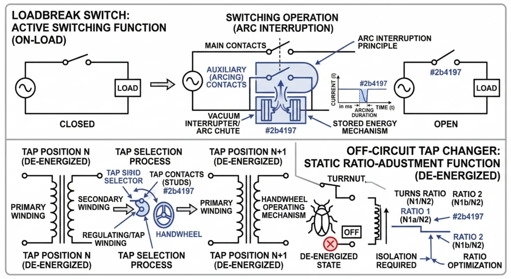
Loadbreak Switch Mechanics: Interrupting Current Under Load
When an operator opens a live distribution circuit, the electrical current fundamentally resists interruption. As the physical contacts part, the current leaps across the growing physical gap, ionizing the surrounding medium and generating a high-temperature plasma arc. A is explicitly engineered to safely manage and extinguish this arc within the sealed, oil-immersed environment of a distribution transformer. A loadbreak switch is a transformer-mounted switching device used to make or break rated current.
The Role of the Stored-Energy Mechanism
The speed of contact separation is critical to successful arc quenching. If the contacts part too slowly, the electrical arc persists, melting the conductive components and rapidly degrading the surrounding dielectric fluid. Because manual hook-stick operation is inherently variable in speed and force, modern loadbreak switches rely entirely on a stored-energy spring mechanism.
When the field technician pulls the external handle, they are not directly separating the internal contacts; rather, they are compressing a heavy-duty mechanical spring. Once the spring reaches its precise mechanical trip point, it releases its stored kinetic energy, driving the contacts apart at a consistent, high velocity. For a standard 630 A loadbreak switch operating in 15/25 kV or 38/40.5 kV networks, this ensures the mechanism clears the arc independent of the operator’s physical technique. To ensure reliable safety margins, these mechanisms are rigorously evaluated against standards such as [NEED AUTHORITY LINK SOURCE: IEEE C37.71 Standard for Subsurface and Vault Load-Interrupting Switches].
[Expert Insight]
Check Spring Tension: During routine maintenance, verify the stored-energy mechanism; a sluggish spring fails to clear the arc effectively, leading to premature contact wear.
Fluid Diagnostics: Inspect the transformer’s dielectric fluid for dissolved combustible gases (DGA) if the switch undergoes frequent load-breaking operations, as normal arc quenching slowly degrades the surrounding oil over time.
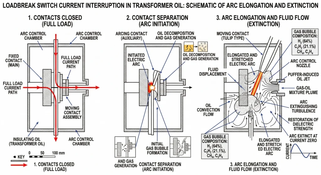
Arc Extinction in Dielectric Fluid
Inside the transformer tank, the switch’s contact assembly operates fully submerged in the transformer’s insulating oil.
When the stored-energy mechanism trips, the contacts typically separate at velocities ≥ 3.0 m/s. As the arc forms between the parting contact tips, its extreme heat instantly vaporizes the adjacent transformer oil. This localized vaporization generates a high-pressure bubble of cooling gases—predominantly hydrogen. The rapid fluid displacement and gas generation actively cool and compress the plasma channel. By the time the alternating current (AC) waveform reaches its natural zero-crossing point, the dielectric strength of the turbulent oil recovers faster than the transient recovery voltage (TRV) can rise, successfully extinguishing the arc. To prevent restriking, the final contact gap distance (often Δd ≥ 50 mm for medium-voltage applications) must be fully established within milliseconds.
Off-Circuit Tap Changer Mechanics: Adjusting Voltage Ratios
While a loadbreak switch actively manages the violent physics of arc extinction, an serves a fundamentally different mechanical purpose. An off-circuit tap changer (also called a de-energized tap changer or off-load tap changer) is a mechanical switching device used to adjust transformer turns ratio only when the transformer is de-energized. Because it lacks any arc-quenching capability, it operates purely as a static bridging device rather than an active interrupter.
Modifying the Transformer Turns Ratio
To compensate for long-term voltage drop across a distribution grid, engineers must physically alter the internal winding configuration of the transformer. The off-circuit tap changer achieves this by functioning as a multi-position selector switch connected directly to specialized tap leads extending from the primary winding. The primary high-voltage winding is universally utilized for this purpose because the corresponding electrical current is lower, which subsequently reduces the physical size and thermal stress on the tap changer contacts.
The mathematical relationship governing this adjustment relies on the fundamental transformer equation, where the voltage ratio is directly proportional to the physical turns ratio (V1 / V2 = N1 / N2). By mechanically shifting the contact bridge across the physical taps, the device alters N1. For instance, in a 13.8 kV distribution network, a standard five-position tap changer typically provides a ±5% regulation range in 2.5% increments. This creates a ΔV of roughly 345 V per step. Because the mechanism operates strictly off-load, the internal contacts are engineered purely for low static resistance (often ≤ 500 μΩ) rather than thermal arc management.
Linear vs. Rotary Contact Architectures
To reliably execute these physical connections inside the oil-filled transformer tank, manufacturers employ two primary structural designs. Linear tap changers utilize a sliding carriage mechanism that moves vertically or horizontally to bridge stationary contact pins. This rack-and-pinion or threaded-shaft approach is highly effective for rectangular coil configurations. Conversely, rotary tap changers arrange the stationary winding contacts in a circular pattern around a central insulating cylinder. When the external handle is turned, a central shaft rotates a set of spring-loaded moving contacts to bridge the required stationary points.
Regardless of the structural geometry, these mechanisms are explicitly rated for specific steady-state loads, typically standardized at 63 A or 125 A across 15 kV, 25 kV, and 35 kV voltage classes. The integrity of the connection relies on high-pressure, wiping-action contacts that mechanically clean themselves of carbonized oil and microscopic oxidation during each movement, ensuring the electrical connection remains secure for decades of uninterrupted service.
Field Consequences: Operating a Tap Changer Under Load
Despite clear warning labels and established safety protocols, field personnel occasionally mistake an off-circuit tap changer for a loadbreak switch, attempting to adjust the distribution voltage while the transformer remains energized. This operational error violates the fundamental application boundary between the two devices, invariably leading to rapid and often catastrophic equipment failure. Because the tap changer lacks a stored-energy spring mechanism and arc-quenching geometry, manual rotation is far too slow to safely manage the resulting electrical plasma.
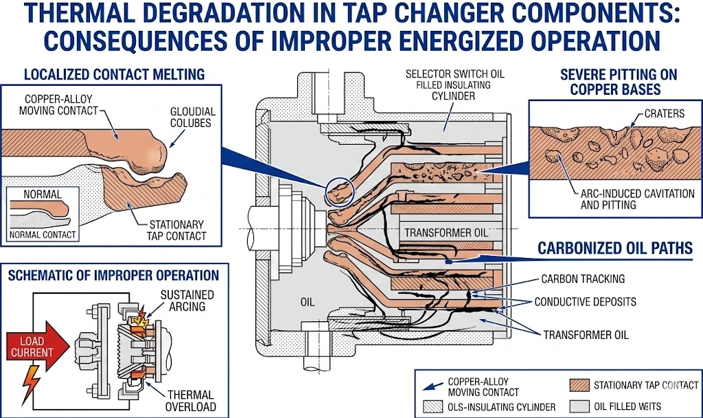
Contact Pitting and Severe Arcing
When a technician breaks the physical contact of a tap changer under a live load—even a relatively light load—the circuit immediately draws a sustained arc across the separating components.
Unlike a loadbreak switch, the off-circuit mechanism cannot separate the contacts fast enough, nor does it create sufficient physical distance to break the plasma channel. If an operator attempts to interrupt even 50 A of load current on a 15 kV distribution system, the localized arc temperature rapidly escalates > 1,000 °C. This intense thermal stress instantly melts the silver or tin contact plating and causes severe pitting on the copper base metal. The contacts physically degrade to the point where they can no longer carry continuous current without extreme localized heating, rendering the tap changer entirely inoperable.
Oil Contamination and Dielectric Breakdown
The secondary consequence of this sustained arcing is the rapid degradation of the transformer’s internal insulation system. The unquenched arc aggressively boils the surrounding dielectric fluid, breaking down the hydrocarbon chains and filling the transformer tank with combustible gases and conductive carbon particulate.
In field post-mortem analyses of these failures, we consistently observe heavy carbon tracking along the tap changer’s insulating shaft and across the internal terminal boards. As the carbon soot suspends in the oil, the fluid’s overall dielectric breakdown voltage plummets, often falling ≤ 20 kV / 2.5 mm. This sudden loss of insulation integrity typically triggers a severe phase-to-phase or phase-to-ground short circuit inside the transformer tank. At this stage, upstream protection devices, such as , must immediately actuate to clear the massive fault current and prevent catastrophic tank rupture.
[Expert Insight]
Implement Physical Lockouts: Always mandate the use of physical padlocks on tap changer operating handles to physically prevent unauthorized or accidental field actuation.
Visual Isolation Confirmation: Establish strict field protocols requiring visual confirmation of open upstream isolators and proper grounding before authorizing any tap adjustments on distribution networks.
Figure 03:Catastrophic contact damage and oil carbonization resulting from operating a tap changer under load.
Engineering Specification Logic for Transformer Accessories
Procurement teams and design engineers cannot treat active switching devices and static ratio adjusters as interchangeable components. Because their operational boundaries differ entirely, the technical specification process requires distinct datasets to ensure field compatibility and prevent premature equipment failure.
Sizing Loadbreak Switches (Current and Voltage Class)
Specifying a loadbreak switch focuses heavily on dielectric strength and active current interruption capabilities. The two primary parameters are the maximum continuous current—typically 630 A for distribution networks—and the system voltage class, such as 15/25 kV or 38/40.5 kV. Additionally, the mechanical layout must be specified, as applications may require Two-Position or Four-Position Sectionalizing designs.
In field installations, particularly in high-altitude environments ≥ 1,000 meters, engineers must carefully evaluate the Basic Impulse Level (BIL). A standard 15 kV class switch is typically rated for a 95 kV BIL, but atmospheric thinning reduces dielectric clearances. If a 15 kV switch is deployed at 2,000 meters without derating, the reduced air density can facilitate phase-to-ground flashovers during lightning transients. Consequently, engineers often upsize the switch to a higher voltage class to maintain adequate safety margins across the open contact gap.
Specifying Tap Changers (Phases and Adjustment Steps)
Conversely, specifying an off-circuit tap changer requires defining the transformer’s internal winding geometry and the desired voltage regulation range. Procurement data must strictly define whether the application requires a specific voltage class, such as 15 kV, 25 kV, or 35 kV, as well as the continuous current rating of the primary winding, which standardizes around 63 A or 125 A.
The core specification metric is the number of adjustment steps. A standard distribution transformer utilizes a multi-position tap changer, providing a nominal center position and equal adjustments in either direction. This is frequently expressed as ± 2 × 2.5%, allowing a maximum voltage correction of 5% above or below the nominal rating. Specifying a mismatch here creates severe manufacturing delays, as the physical contact bridge will not align with the transformer’s internal lead breakouts.
Partnering for Reliable Transformer Components
Whether configuring a new distribution network or retrofitting existing pad-mounted equipment, selecting the correct switching and protection devices is critical for long-term grid stability. Specifying the wrong component not only delays procurement but can introduce severe operational hazards into the field.
At ZeeyiElec, our team supports product selection, technical details, and quotation response for OEM/distributor projects. We provide tailored technical feedback and model matching based on your specific requirements. Whether your team is sourcing 630 A loadbreak switches for a 25 kV network or integrating multi-position tap changers, partnering with an experienced manufacturer helps mitigate specification errors. We back our complete portfolio of components and with rigorous factory testing to ensure performance aligns with standard baseline expectations.
For large-scale utility projects or specialized OEM/ODM configurations, our facility is equipped to handle bulk order support with standard manufacturing lead times typically ranging from 15 ≤ t ≤ 30 days, depending on the complexity of the 15/25/35 kV class requirements. By maintaining strict quality control over every contact mechanism and stored-energy spring, we strive to deliver components that perform reliably under demanding field conditions.
If your engineering team needs support translating project specifications into actionable procurement data, share your requirements with us. Our export team is prepared to provide a comprehensive quotation and technical evaluation for your next distribution project.
Frequently Asked Questions
Can a loadbreak switch adjust the voltage of a transformer?
No, a loadbreak switch is strictly designed to make or break the circuit under load—typically handling continuous currents of 630 A at 15 kV to 35 kV—but it cannot alter the physical winding ratio. Voltage regulation requires an off-circuit tap changer operating strictly within de-energized parameters.
What happens if you switch an off-circuit tap changer while energized?
Operating an off-circuit tap changer under load draws an unquenchable electrical arc because the device lacks a high-speed spring mechanism and arc-extinguishing geometry. This operational error instantly melts the contacts, carbonizes the insulating oil, and generally results in catastrophic, irreversible transformer failure.
Do both components mount on the exterior of the transformer tank?
Yes, both devices feature external operating handles or motor operators accessible to field personnel for manual actuation. However, while the physical interfaces are external, their critical internal contact mechanisms are submerged deeply within the transformer’s dielectric fluid to utilize the oil’s vital insulating and cooling properties.
What is the typical current rating for a distribution loadbreak switch?
Standard distribution pad-mounted loadbreak switches are typically rated for 630 A of continuous and load-interrupting current. The specific sizing depends entirely on the network’s maximum load requirements, though engineering safety margins often dictate utilizing components rated slightly above the nominal operational baseline to handle transient conditions.
Can I replace a broken tap changer without draining the transformer oil?
No, because the tap changer’s internal contact assembly directly bridges the active primary windings submerged inside the tank, the component cannot be safely extracted while immersed. The transformer must be completely de-energized and the dielectric fluid physically drained below the component’s mounting level to perform any field replacement or maintenance.
How many positions does a standard loadbreak switch have?
A standard distribution loadbreak switch is generally configured in a two-position (on/off) or four-position (V-blade or T-blade) layout to enable loop-feed sectionalizing. This differs fundamentally from a tap changer, which usually features 5 to 7 operational positions (for example, providing a ± 2 × 2.5% regulation range) designed exclusively for fine voltage tuning rather than circuit routing.
yoyo shi
Yoyo Shi writes for ZeeyiElec, focusing on medium-voltage accessories, transformer components, and cable accessory solutions. Her articles cover product applications, technical basics, and sourcing insights for global electrical industry buyers.