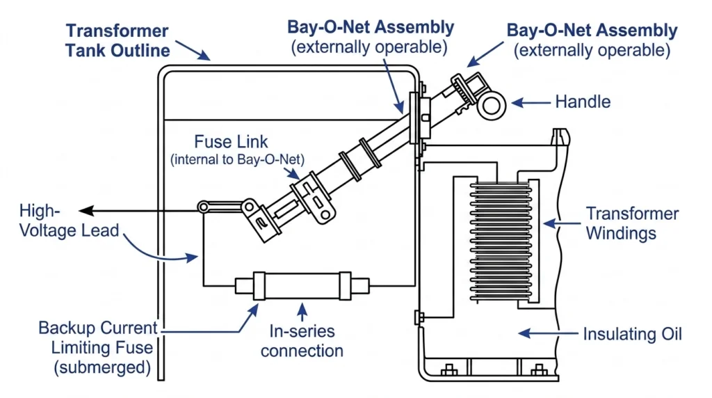
Two-stage transformer protection coordinates a Bay-O-Net fuse assembly with a backup current limiting fuse wired in series. Transformer protection requires two fuse technologies working in sequence: Bay-O-Net fuses clear low-to-moderate faults up to approximately 3,500 amperes, while current limiting fuses interrupt high-magnitude faults exceeding this threshold within a half-cycle. This coordination logic creates continuous protection across the entire fault current spectrum—from mild overloads to bolted faults reaching 50,000 amperes or more.
Figure 01:Schematic representation of series-connected expulsion and current limiting fuses within an oil-filled transformer tank.
The Fault Current Spectrum
Transformers face fault currents spanning three orders of magnitude. During normal operation, load currents measure in tens or hundreds of amperes. During a bolted fault, currents spike to thousands or tens of thousands of amperes within milliseconds.
The severity of these electrical anomalies requires protection components capable of managing diverse thermal and mechanical stresses. For instance, on a typical 15 kV distribution network, a secondary short circuit might generate fault currents ≤ 2,500 A, while a primary-side fault can yield asymmetrical currents ≥ 40,000 A. The thermal energy released during these events is proportional to I2t (ampere-squared seconds). Protecting the transformer core and windings from this thermal deformation requires adhering strictly to through-fault duration limits, often modeled in accordance with [VERIFY STANDARD: IEEE Std C57.109 for liquid-immersed transformer through-fault duration limits].
Why a Single Fuse Technology is Insufficient
No single fuse technology can safely handle the full spectrum of fault currents. If a standalone is subjected to a 30,000 A primary fault, the rapid expansion of gases during the expulsion process can exceed the mechanical limits of the housing, risking a catastrophic rupture of the transformer tank.
Conversely, a is designed to interrupt high fault currents before they reach destructive peak levels. In transformer protection systems, it helps reduce thermal and mechanical stress. However, the internal silver elements of a current limiting fuse require massive thermal energy to melt. If relied upon to clear a low-level 150 A secondary overload, the fuse will not operate fast enough, allowing the transformer’s insulating oil to dangerously overheat and degrade the winding insulation. By combining both devices in series, engineers ensure that every fault magnitude is intercepted by the component physically optimized to clear it.
A bay-o-net fuse assembly is a serviceable protection interface used in oil-filled distribution transformers. Designed as an expulsion-style device, it serves as the primary line of defense against low-magnitude electrical anomalies. By physically submerging the interchangeable fuse link within the transformer’s dielectric fluid, the assembly can react not only to electrical overcurrents but also to excessive fluid temperatures, providing a highly reliable dual-sensing protective mechanism.
Overload Detection and Secondary Faults
Bay-O-Net fuses are specifically engineered to clear low-to-moderate faults up to approximately 3,500 amperes. These faults typically originate on the secondary side of the distribution network, such as low-voltage short circuits, bolted secondary faults, or prolonged equipment overloads. The fuse element operates by reacting to the total thermal energy in its immediate environment. Because it is immersed in the transformer oil, the element responds simultaneously to the I2R heating generated by the electrical current passing through it and the ambient temperature rise (ΔT) of the surrounding dielectric fluid.
If a distribution transformer experiences a sustained 150% overload, the slow accumulation of heat in the oil will eventually cause the Bay-O-Net link to melt. This action isolates the transformer before the internal kraft paper insulation reaches its thermal degradation threshold. This dual-sensing capability is critical for preventing thermal runaway in standard 15/25kV class oil-filled distribution transformers.
Physical Operation Within Dielectric Fluid
When a secondary fault or severe overload occurs, the internal fuse element—often constructed from a calibrated tin or silver alloy—melts and separates. This physical break instantly draws an electrical arc inside the fuse’s internal cartridge. The intense heat of this arc reacts with the cartridge’s internal lining (typically a solid ablative material like horn fiber), rapidly vaporizing it and generating a localized burst of de-ionizing gases.
The rapid expansion of these expelled gases forcefully elongates and cools the arc, ultimately blowing it out and safely interrupting the circuit at the next natural alternating current zero-crossing. Because this expulsion process generates physical pressure within the fuse housing and the broader transformer tank, operational field safety is paramount.
[Expert Insight] Field Extraction Safety Protocols
Pressure Equalization: Before utilizing a hot-stick to extract a potentially operated Bay-O-Net holder, line workers must manually pull the transformer’s pressure relief valve (PRV) to equalize internal tank pressure.
Seal Integrity: Failing to vent the tank can result in pressurized hot oil bypassing the dead-front safety seals during extraction, causing severe burns or environmental contamination.
Fluid Level Verification: Always verify that the oil level is at the correct operation mark; operating an expulsion fuse in the vapor space instead of submerged in oil drastically reduces arc-quenching capability.
Current Limiting Fuses: Interrupting Catastrophic Faults
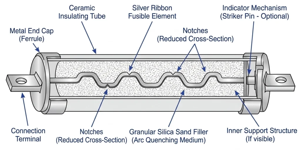
Figure 02:Internal architecture of a current limiting fuse detailing the notched silver element and silica sand matrix.
While the expulsion-style Bay-O-Net fuse handles moderate issues, a current limiting fuse takes over for severe events. It is engineered specifically to manage catastrophic electrical failures by aggressively restricting the flow of energy.
Half-Cycle Clearing Dynamics
The internal architecture of a current limiting fuse is distinctly different from an expulsion fuse. It typically consists of a high-purity silver ribbon element, intricately stamped with reduced cross-sectional areas (notches), completely embedded in silica sand within a sealed fiberglass or epoxy housing.
When subjected to a catastrophic bolted fault—such as a 50,000 A primary-side short circuit—the silver element melts almost instantaneously at these constricted notches. This vaporization ignites multiple electrical arcs in series. Unlike standard expulsion devices that must wait for a natural alternating current zero-crossing, a current limiting fuse forces the current to zero within the first half-cycle (typically ≤ 8.3 milliseconds for a 60 Hz distribution system). The immense heat of the arc (≥ 3,000 °C) violently melts the surrounding silica sand, fusing it into an insulating glass-like fulgurite. This phase change absorbs massive thermal energy and rapidly introduces a high resistance (Ω) into the circuit, choking the current trajectory before it reaches its prospective asymmetrical peak.
Energy Restriction and Transformer Survival
By artificially driving the current to zero, the fuse drastically reduces the total let-through energy acting upon the transformer’s core and coils. For engineers specifying , evaluating this let-through energy is paramount. The design and testing of these components are strictly governed by industry protocols [NEED AUTHORITY LINK SOURCE: IEEE Std C37.47 for high-voltage distribution class current-limiting type fuses].
From a field operations perspective, a current limiting fuse operation is a severe event. Unlike a blown Bay-O-Net link—which often simply indicates a temporary secondary overload—a blown current limiting fuse almost exclusively signifies a major internal transformer fault or a catastrophic downstream failure. Field crews must never simply replace the fuse and re-energize; comprehensive diagnostic testing, including winding resistance measurements and Dissolved Gas Analysis (DGA) of the dielectric fluid, must be performed to ensure the transformer’s internal insulation matrix has not been permanently compromised.
Coordination Logic: Mapping the Time-Current Curves (TCC)
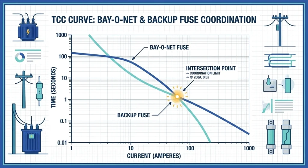
Figure 03:Log-log graph demonstrating the critical crossover boundary between a minimum melting curve and a total clearing curve.
Achieving continuous protection relies on mapping Time-Current Characteristic (TCC) curves to determine the exact crossover point where the protective burden shifts from the expulsion link to the backup fuse.
Defining the Minimum Melting Curve
The selection process begins with analyzing the minimum melting curve of the expulsion link. This curve plots the specific time required for the internal element to begin melting at various fault current levels. For proper coordination, this curve must sit comfortably above the transformer’s normal full-load current and anticipated magnetizing inrush currents. The Bay-O-Net link must be allowed to independently melt and clear low-to-moderate faults up to approximately 3,500 amperes. If the curve is specified too far to the left (too sensitive), engineers risk nuisance tripping during standard energization sequences.
Establishing the Total Clearing Curve Boundary
The total clearing curve of the backup fuse represents the maximum time required to detect, melt, and fully extinguish the electrical arc. The fundamental rule of two-stage coordination is that the TCC curves of the two fuses must intersect. This intersection establishes the critical crossover boundary. Below this specific current magnitude, the expulsion link operates; above it, the current limiting fuse takes over. For a typical 15 kV distribution transformer, this crossover point is engineered to occur between 1,200 A and 3,000 A. The intersection must occur strictly ≤ the maximum interrupting rating of the Bay-O-Net assembly to prevent catastrophic housing failure.
Alignment with IEEE/IEC Protection Standards
Selecting proper protective hardware based on TCC mapping requires strict adherence to international standard curves. Authoritative guidelines, such as IEEE Std C57.109, dictate the through-fault duration limits and mechanical damage boundaries of the transformer itself. The combined coordination profile of the paired fuses must nestle cleanly below the transformer’s damage curve. In field applications, engineers must physically verify that the manufacturer’s published TCC curves align with these operational boundaries.
[Expert Insight] TCC Mapping Best Practices
Verify Intersection Points: Always plot the specific Bay-O-Net minimum melt curve against the backup fuse’s total clearing curve on the same log-log paper to visually confirm the crossover point.
Check Maximum Interrupting Rating: Ensure the crossover occurs at a current magnitude well below the expulsion link’s stated maximum interrupting capacity (typically < 3,000 A).
Account for Pre-Loading: Remember that pre-existing load currents pre-heat the fuse elements, effectively shifting the minimum melting curves slightly to the left in real-world operating scenarios.
Field Selection Parameters for Coordinated Pairs
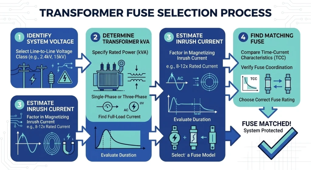
Figure 04:Systematic selection flowchart for engineering coordinated fuse pairs based on transformer voltage and kVA ratings.
Selecting the correct combination of fuses requires a systematic evaluation of electrical parameters to ensure safe fault interruption without nuisance tripping. For engineers and field personnel, this coordination logic must be translated into actionable selection steps prior to transformer installation and energization.
Matching Voltage Class and BIL Ratings
The foundational step in the selection framework is matching the fuse hardware to the system’s operational voltage and insulation withstand levels. A distribution transformer operating on a 14.4 kV network typically requires fuse assemblies rated for the 15 kV voltage class. Additionally, the fuse housings and internal insulating components must match or exceed the transformer’s Basic Impulse Level (BIL). For a standard 15/25 kV class pad-mounted transformer, the components must safely withstand a 125 kV BIL transient lightning or switching surge without experiencing a flashover or internal dielectric breakdown.
Sizing Based on Transformer KVA and Impedance
Once the voltage class is firmly established, engineers must calculate the expected full-load continuous current based on the transformer’s kVA rating.
For a three-phase 1,000 kVA transformer operating at 12.47 kV (phase-to-phase), the nominal full-load current (FLA) is approximately 46.3 A. However, the fuse selection must also account for the transformer’s internal impedance (%Z), which directly dictates the maximum secondary bolted fault current. A transformer with a standard 5.75% impedance will restrict the maximum secondary fault current to roughly 17.4 × FLA (approximately 805 A). The specified Bay-O-Net link must have an interrupting rating well above this 805 A threshold to clear secondary shorts, while the backup current limiting fuse is sized to handle primary-side internal faults that bypass this impedance limitation entirely.
Accounting for Magnetizing Inrush Currents
A prevalent field installation failure occurs when engineers size the Bay-O-Net link too closely to the nominal load current, leading to immediate nuisance tripping upon energizing the transformer.
When a cold distribution transformer is connected to the grid, it draws a massive, short-duration magnetizing inrush current to establish the core’s magnetic field. This transient surge typically reaches 10 to 12 × FLA for a duration of 0.1 seconds. To prevent the expulsion link from prematurely melting, its minimum melting TCC curve must be positioned to the right of this inrush point (e.g., safely allowing ≥ 550 A for 0.1 seconds on a 1,000 kVA unit). Field commissioning teams must ensure the selected link accommodates these energization spikes while still intersecting the backup fuse curve safely below the 3,000 A maximum interrupting boundary.
Operational Realities: Managing Coordination in the Field
While engineering TCC curves in a controlled environment is straightforward, maintaining that strict two-stage coordination in the field presents unique operational challenges. Distribution transformers face severe weather, continuous load cycling, and periodic maintenance interventions that can inadvertently compromise the protective scheme.
The Danger of Improper Link Replacement
A common field failure mode occurs during emergency outage restorations. When a transformer trips, maintenance crews might find a blown Bay-O-Net fuse link. Eager to safely restore power to the circuit, a lineman might replace a blown 65 A isolation link with a larger 140 A link simply because it is the only size available on the service truck at that moment.
This field mismatch completely destroys the carefully engineered coordination logic. By installing a heavier link, the minimum melting curve shifts drastically to the right. Consequently, the critical crossover point with the backup current limiting fuse is pushed higher, potentially exceeding the expulsion assembly’s maximum interrupting rating. If a secondary fault ≥ 3,000 A occurs, the improperly sized link may attempt to clear it instead of allowing the current limiting fuse to operate, resulting in a violent internal expulsion failure that can rupture the transformer tank. Additionally, if the backup fuse has operated, field protocols dictate that the Bay-O-Net link must also be replaced, even if it visually appears intact. The preceding high-magnitude fault likely subjected the expulsion link to severe thermal stress, degrading its mechanical tensile strength.
Oil Contamination and Thermal Variations
Because Bay-O-Net assemblies are physically submerged, their arc-quenching performance and thermal sensing capabilities are directly tied to the physical condition of the transformer’s dielectric fluid. Routine maintenance must account for fluid degradation.
Field conditions such as degraded gasket seals can lead to aggressive moisture ingress over a distribution transformer’s 20-to-30-year lifespan. If the dielectric oil’s moisture content rises ≥ 35 ppm, or its dielectric breakdown voltage drops ≤ 30 kV, the fluid loses its ability to effectively cool and de-ionize the explosive gases expelled during a fuse operation. Similarly, extreme ambient temperatures alter the baseline oil temperature. A high baseline reduces the ΔT required to melt the dual-sensing fuse element, making the Bay-O-Net hypersensitive to normal load fluctuations and dramatically increasing the risk of nuisance tripping during peak summer demand.
Secure Your Distribution Network with Verified Protection
Specifying the correct coordination boundary between expulsion links and backup current limiting fuses is critical for equipment survival. However, transformer protection is only one segment of overall distribution network reliability. A fully protected system requires verifiable performance at every interface, from the primary tank housing down to the terminating the underground lines.
At ZeeyiElec, we bridge the gap between theoretical time-current curves and practical field deployment. Whether you are sizing coordinated fuse pairs for a standard 15/25 kV pad-mounted transformer or specifying complete cold shrink terminations for a 35 kV distribution ring, our engineering team provides direct technical validation. We analyze your specific fault current availability, continuous load requirements, and environmental parameters to ensure every component aligns with your project’s unique operational constraints.
Avoid the cascading project delays caused by mismatched specifications or incomplete RFQ data. Send your single-line diagrams, required transient withstand ratings, and target installation environments to our technical team. We provide complete OEM/ODM model matching, rigorous export documentation support, and structured quotation responses designed specifically for procurement professionals and field engineers.
Ready to finalize your procurement package? Contact ZeeyiElec for a comprehensive technical review. Our engineers typically provide actionable feedback and verified component matching within ≤ 24 hours, ensuring your distribution network remains fully protected against both low-level secondary overloads and ≥ 40,000 A catastrophic primary faults.
Frequently Asked Questions
What happens if a Bay-O-Net fuse is used without a current limiting fuse?
If exposed to a high-magnitude bolted fault exceeding its interrupt rating (typically ≥ 3,000 A), a standalone Bay-O-Net fuse may fail catastrophically and rupture the transformer tank. It must always be paired with a current limiting fuse for full-spectrum protection in high-capacity distribution networks.
Can a current limiting fuse clear a low-level overload?
A backup current limiting fuse is not designed to clear low-magnitude secondary overloads or impedance faults, as its internal element requires massive thermal energy to melt. Relying on it for low-level faults risks prolonged equipment overheating, which is why the Bay-O-Net link is required to handle currents ≤ 3,500 A.
How do you determine the correct crossover point for transformer fuses?
The crossover point is established by overlaying the Time-Current Characteristic (TCC) curves of both fuses, ensuring the intersection occurs well below the maximum interrupting rating of the Bay-O-Net link. This critical transfer point typically falls between 1,000 A and 3,000 A, varying based on the transformer’s specific kVA rating and primary voltage class.
Why do current limiting fuses use silica sand?
High-purity silica sand surrounds the conductive silver fuse element to rapidly absorb the intense thermal energy generated during a high-magnitude short circuit. When the electrical arc ignites, the sand melts into a glass-like fulgurite insulator, mechanically choking and quenching the arc within a single half-cycle (typically ≤ 8.3 ms for 60 Hz systems).
Do both fuses need to be replaced if the current limiting fuse operates?
Yes, if the backup current limiting fuse has operated to clear a catastrophic fault, the Bay-O-Net fuse link must also be replaced even if it visually appears intact. The preceding high-magnitude fault surge likely compromised the expulsion link’s thermal integrity and mechanical tensile strength before the circuit was fully isolated.
What is the maximum fault current a Bay-O-Net assembly can handle alone?
Standard Bay-O-Net fuse assemblies are generally engineered to safely interrupt fault currents between 1,000 A and 3,500 A, depending on the specific dielectric fluid temperature and system operating voltage. Any prospective fault current projected to exceed this threshold requires the immediate, series-connected intervention of a backup current limiting fuse.
yoyo shi
Yoyo Shi writes for ZeeyiElec, focusing on medium-voltage accessories, transformer components, and cable accessory solutions. Her articles cover product applications, technical basics, and sourcing insights for global electrical industry buyers.