Medium voltage electrical accessories are engineered interface components designed to manage concentrated electrical stress, restore insulation integrity, and provide environmental sealing at critical connection points within power distribution networks. Operating primarily within the 1 kV to 36 kV system voltage spectrum, these devices prevent premature electrical breakdown at vulnerable interfaces, ensuring grid reliability and equipment protection.
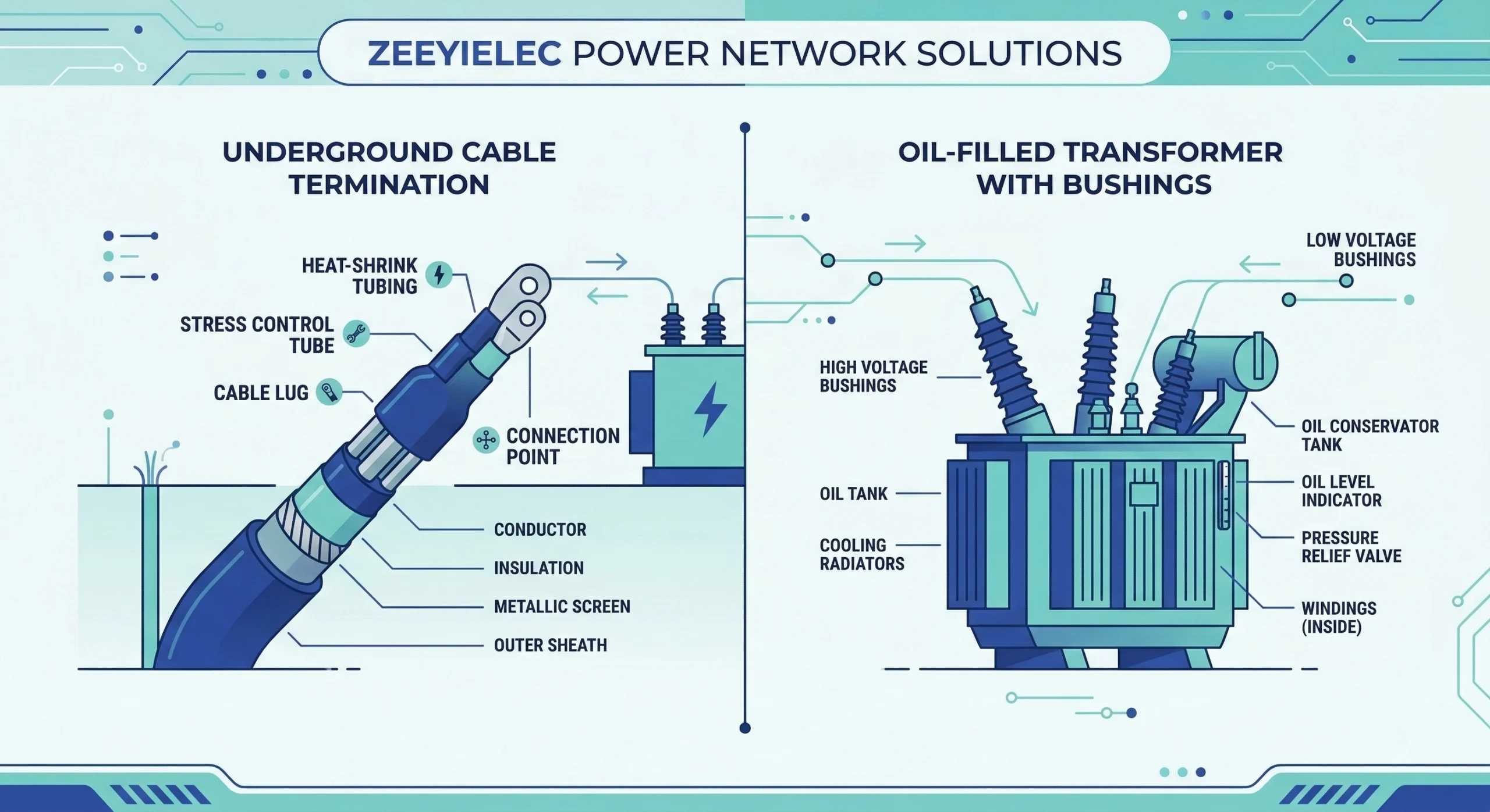
Figure 01:Typical interface points for medium voltage cable and transformer accessories in a standard distribution grid.
Cable System Interfaces
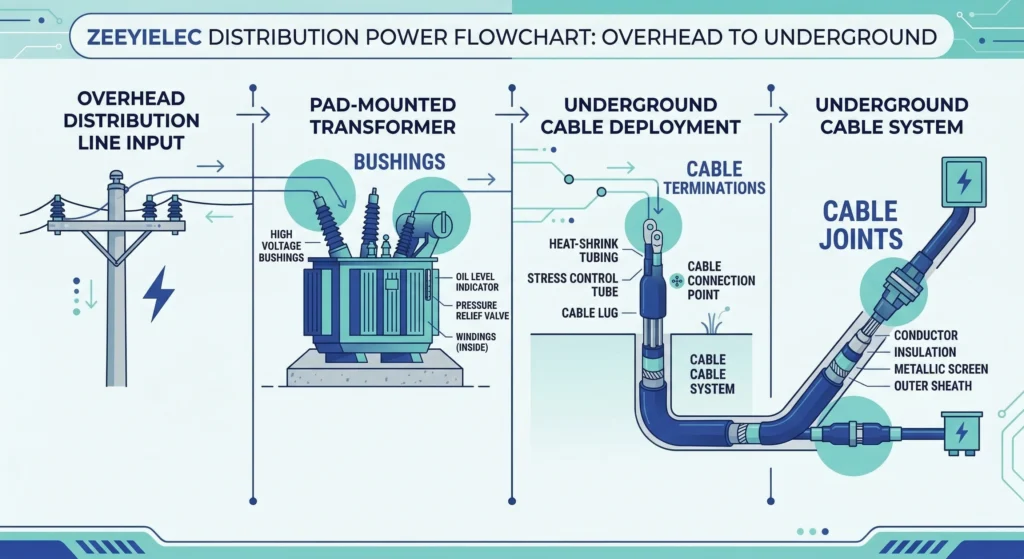
In power distribution networks, cable accessories—specifically terminations, joints, and separable connectors—must frequently accommodate substantial conductor cross-sections up to 800 mm2 while maintaining absolute dielectric stability. These components are structurally engineered to restore electrical insulation and carefully manage electrical stress fields at cable endpoints. The physical integrity of these interfaces directly determines whether a power cable system operates reliably for its intended 25–40 year service life or succumbs to early failure.
Transformer Integration Points
On the equipment side, act as the vital structural bridges between internal mechanisms and the external grid. They are essential interface components that support insulated connections, coordinate fault protection, and enable switching operations within distribution transformer systems. For instance, components like bushings must physically bridge the transformer’s internal insulation system with external connections, while tap changers introduce moving mechanical contacts into sealed, oil-filled environments.
The Role of Dielectric Integrity
The fundamental physics governing any medium voltage accessory revolves around the prevention of partial discharge and catastrophic flashovers. When a factory-extruded shielded power cable is stripped for termination, or a transformer tank is penetrated by a primary conductor, the previously uniform electrical field becomes severely distorted. Accessories are engineered to manage this concentrated dielectric stress using specific structural geometries, stress-grading mastics, and specialized insulating materials. By actively controlling the electric field distribution, these components prevent the localized high-voltage stress from exceeding the dielectric strength of the surrounding air or insulation materials.
Structural Materials and Component Architecture
The long-term reliability of medium voltage accessories depends entirely on the molecular stability and physical properties of their constituent materials. Engineers must evaluate these components based on their dielectric strength, thermal endurance, and environmental resilience.
Polymeric Insulation Materials
In modern distribution networks, polymeric materials dominate the cable accessory market. The fundamental engineering choice often comes down to evaluating technologies. Cold shrink accessories predominantly utilize highly elastic silicone rubber or EPDM (Ethylene Propylene Diene Monomer), which are pre-expanded on a removable plastic core. This provides a constant active radial pressure against the cable jacket, ensuring a void-free seal that expands and contracts with the cable during thermal load cycling. Heat shrink components rely on cross-linked polyolefin polymers that possess a “thermal memory,” collapsing permanently when a thermal source is applied. The material formulation for these accessories must strictly comply with IEC 60502-4 standards, which dictate the rigorous electrical and mechanical performance requirements for extruded solid dielectric cable accessories. [NEED AUTHORITY LINK SOURCE] for IEC 60502-4 standard specifications.
Traditional Porcelain and Resin Structures
For transformer interfaces, structural rigidity and high-temperature tolerance are paramount. Medium voltage transformer bushings frequently utilize ANSI or DIN standard porcelain, or advanced epoxy cast resins. These materials offer exceptional tracking resistance and high mechanical cantilever strength. Conversely, low voltage secondary bushings often incorporate High Temperature Nylon (HTN) or porous resin compounds designed to handle continuous current ratings ranging from 600 A up to 5000 A+. A critical electrical metric for these insulating bodies is the Basic Impulse Level (BIL); for example, a standard 15/25 kV class accessory must structurally and electrically withstand a 150 kV BIL surge to adequately protect against lightning and switching transients.
Conductive and Stress-Relief Elements
Beyond bulk insulation, accessories rely heavily on internal semiconductive layers and stress-relief mastics to maintain dielectric stability. These elements actively shape and diffuse the electrical field at the termination point of the cable shield. Experience from field engineers consistently highlights that a common failure mode originates from the improper application of void-filling mastic during jointing. If an installation crew leaves even a microscopic 1 mm air gap near the semiconductor cutback, the localized dielectric stress multiplies, rapidly initiating partial discharge that erodes the insulation. To combat this, High-K (high dielectric constant) stress control tubes are integrated into the accessory body to refract electrical stress lines.
[Expert Insight] Material Selection Priorities
Cold Shrink for Active Environments: Use silicone-based cold shrink when facing high thermal load cycling; the active radial pressure continuously adapts to cable expansion and contraction.
Resin/Epoxy for Mechanical Load: Specify cast resin bushings over traditional porcelain when cantilever strength and vibration resistance are primary concerns in heavy industrial settings.
Mastic Application Realities: Never underestimate void-filling mastic during installation. A tiny 1 mm air gap at the semiconductor cutback is the leading cause of early partial discharge failure.
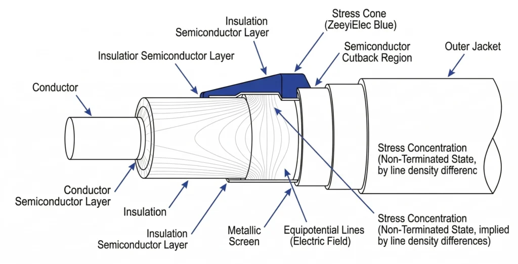
Physics of Operation and Dielectric Stress Management
When a medium-voltage shielded cable is prepared for termination or jointing, the grounded semiconductive screen is abruptly stripped away. This physical cutback creates an extreme concentration of electrical equipotential lines at the edge of the shield. Without mitigation, the localized voltage gradient rapidly exceeds the dielectric breakdown strength of the surrounding air or insulation, leading to tracking and eventual catastrophic flashover. Similarly, medium voltage transformer bushings act as insulated pass-through components installed on the transformer tank wall, designed to safely manage concentrated stress where the live current passes through the grounded metal tank.
Figure 02:Geometric and refractive stress control mechanisms actively manage the concentrated voltage gradient at the shield cutback.
Geometric Stress Control
The traditional and highly reliable method of mitigating concentrated voltage gradients relies on physical geometry. By utilizing a molded conductive elastomeric material shaped like a trumpet—commonly known as a stress cone—the ground potential is smoothly flared outward and away from the primary conductor. This structural architecture physically forces the equipotential lines to spread apart, gradually reducing the electrical stress at the shield terminus to safe operational limits. For optimal dielectric stability in a 15 kV or 35 kV network, the internal radial stress is typically maintained below 2.5 kV/mm. This mechanism is standard in many pre-molded separable connectors and cold shrink terminations where physical space allows for the required dimensional expansion.
Refractive Stress Control
Modern heat shrink and specific cold shrink technologies frequently employ refractive stress control to maintain a slimmer profile. Instead of relying on bulk physical geometry, this method utilizes specialized stress-grading mastics and tubes formulated with high dielectric constant (High-K) materials. These advanced components possess a specific relative permittivity (εr) typically ranging from 15 to 30. When applied tightly over the semiconductor cutback, the High-K material effectively “refracts” the electrical equipotential lines, drawing them out and distributing the voltage gradient (ΔV) evenly along the length of the cable insulation. This prevents the ionization of microscopic air gaps (often ≤ 10 μm) at the critical interface. Rigorous adherence to manufacturing tolerances, such as [VERIFY STANDARD: IEEE 48 requirements for termination stress relief under high-voltage continuous loads], is required to ensure these refractive layers do not suffer from thermal runaway under operational extremes.
Technical Parameters and Selection Logic
Selecting the correct medium voltage components requires a systematic evaluation across multiple electrical and dimensional parameters. In field assessments across industrial installations, improper accessory selection accounts for approximately 35% of cable system failures within the first five years of operation. Avoiding these premature failures means matching the accessory’s dielectric strength, thermal capacity, and dimensional compatibility precisely to the distribution network.
System Voltage Classifications
The foundational metric for any accessory is its system voltage class, which dictates the required insulation thickness and clearance distances. Accessories are typically categorized into 15 kV, 25 kV, and 35 kV classes. However, engineers must also specify the Basic Impulse Insulation Level (BIL) to ensure the component survives transient overvoltages. For instance, a 15/25 kV bay-o-net fuse assembly is engineered with a 150 kV BIL to withstand lightning and switching surges in oil-filled distribution transformers.
Continuous and Short-Circuit Current Ratings
Components must carry standard load currents continuously without exceeding thermal limits, while also surviving extreme fault conditions. For example, a standard loadbreak switch is typically rated for a continuous current of 630 A. During a bolted fault, however, currents can spike to tens of thousands of amperes within milliseconds. To protect the system, current limiting fuses are coordinated to interrupt high-magnitude short-circuit currents frequently ≥ 50,000 A. Engineers verify that contact resistance remains ≤ 50 μΩ during normal operation to prevent dangerous temperature rises that degrade surrounding insulation.
Parameter Comparison for Medium Voltage Accessories
To bridge the gap between technical specifications and procurement, the following table maps standard voltage classes to their typical accessory parameters.
Environmental Protection Ratings
Beyond pure electrical metrics, environmental factors heavily influence selection logic. Field installation realities show that components deployed in coastal or heavy industrial zones face severe contamination. In these scenarios, specifying an accessory with an extended creepage distance is mandatory to prevent surface tracking and dry-band arcing over the insulation.
[Expert Insight] Specification Checks
BIL Matching: Always verify that the accessory’s Basic Impulse Level (BIL) strictly matches or exceeds the transformer’s nameplate BIL rating to prevent transient flashovers.
Creepage Expansion: In coastal zones with high salt spray or heavy industrial pollution, increase standard creepage distance specifications by at least 20% to mitigate dry-band arcing.
Fault Coordination: Ensure current limiting fuses are properly matched with upstream breakers and downstream Bay-O-Net fuses to interrupt high-magnitude faults before they reach destructive thermal limits.
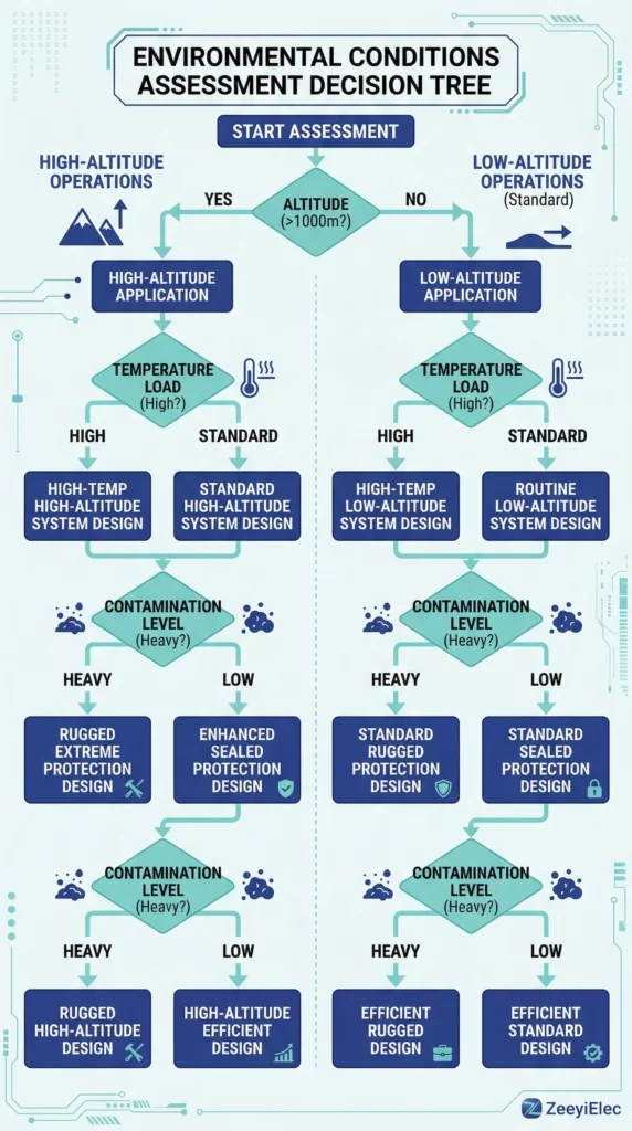
Field Installation Realities and Operating Environments
Field data consistently shows that proper accessory selection accounts for only part of the reliability equation. Execution during installation carries equal or greater weight. Whether commissioning a 15kV termination in a substation switchgear or inspecting an underground splice in a duct bank, field personnel must rigorously account for local environmental extremes. The ultimate operational lifespan of these power system components is heavily dictated by both the precision of the installation crew and the ongoing severity of the physical environment.
Figure 03:Systematic environmental assessment prevents premature accessory failure caused by altitude derating or heavy contamination.
Altitude and Temperature Derating
Installations situated at high elevations present unique dielectric challenges for power distribution networks. As altitude increases, ambient air density decreases, which fundamentally lowers the flashover voltage threshold of external insulation components. For projects exceeding 1,000 meters above sea level, engineers must apply specific dielectric derating factors or proactively select components with extended strike distances to maintain the required Basic Impulse Level (BIL). Simultaneously, managing thermal dissipation is a critical field reality. When a medium voltage power cable operates near its maximum continuous load, internal conductor temperatures can routinely reach 90 °C. This thermal energy transfers directly into the accessory body. If the ambient environment is already hot, the combined thermal load (often modeled by calculating the ΔT rise) can prematurely accelerate the polymer cross-linking decay in silicone or EPDM elastomers, gradually reducing their critical active radial pressure over the cable.
Moisture Ingress and Contamination Challenges
When preparing and installing joints in underground trenches or confined vaults, moisture ingress remains a primary catalyst for early tracking failures. If the relative humidity during the splicing procedure exceeds optimal limits, microscopic water droplets can become trapped beneath the insulation tubing. Over time, this trapped moisture vaporizes and ionizes under the high localized voltage stress, often resulting in dangerous surface leakage currents ≥ 500 μA that slowly carbonize the inner polymeric interfaces. Furthermore, in heavily contaminated coastal or industrial environments, airborne salt spray, chemical dust, and particulate matter settle on the outer insulating sheds of terminations and bushings. This contamination layer effectively shortens the functional creepage distance, drastically increasing the risk of dry-band arcing and eventual catastrophic flashover if routine maintenance and cleaning are neglected.
Diagnostic Workflows for Common Field Failures
A 15 kV cold shrink termination fails at month fourteen. The installation crew blames the accessory, procurement suspects a counterfeit batch, and the site engineer points to a recent lightning event. Three theories, one failure, zero certainty—and a replacement already on order before anyone examines the evidence. Systematic field failure diagnosis isolates root causes before repeat failures occur. By following a structured workflow, field engineers identify what actually failed, why it failed, and what conditions allowed the failure to develop.
Initial Visual Inspection Protocols
The first phase of any diagnostic workflow begins before the faulted component is removed from the switchgear or distribution pole. Field crews must document the external condition of the accessory and the surrounding environment. Key indicators include signs of severe moisture tracking, UV degradation on polymeric sheds, or explosive rupture points. Finding a carbonized tracking path exceeding 50 mm along the outer surface often points to heavy environmental contamination or improper clearance distances rather than an internal dielectric flaw.
Electrical Testing and Verification
When an accessory has not catastrophically faulted but shows signs of impending failure, engineers deploy non-destructive electrical testing to verify insulation integrity. Insulation resistance (IR) is typically measured using a 5 kV or 10 kV megohmmeter. An insulation resistance value dropping to ≤ 500 MΩ strongly indicates severe moisture ingress or advanced carbonization within the splice body. Additionally, Very Low Frequency (VLF) testing at 0.1 Hz is frequently utilized to assess dielectric health without overstressing aged cables. During these tests, detecting partial discharge (PD) levels ≥ 250 pC at the operating voltage (U0) warns that internal voids or poor semiconductor cutbacks are actively eroding the insulation matrix.
Root Cause Isolation Steps
The final stage involves a forensic teardown of the faulted component. This systematic dismantling isolates whether the failure originated from a manufacturing defect, operational over-voltage, or, most commonly, installation error. Field engineers meticulously measure the internal dimensions, such as the semiconductor cutback length and insulation stripping distances. If a cutback deviates by just 5 mm from the manufacturer’s instruction, the geometric stress control is compromised, leading to concentrated voltage gradients. [VERIFY STANDARD: IEEE 400.2 guidelines for field testing and failure analysis of shielded power cable systems] provides standard methodologies for this isolation process, ensuring crews do not simply replace a failed joint without correcting the underlying workmanship or environmental issue.
Specify Your Project Requirements
A missing data point in a Request for Quotation (RFQ) does not simply slow down procurement; it triggers clarification loops that can noticeably delay project schedules. Whether your project requires sourcing cold shrink terminations for an underground distribution network or off-circuit tap changers for an oil-filled transformer, providing a complete technical profile ensures accurate model matching and long-term environmental compatibility.
Essential RFQ Data Points
To bypass generic quotations and receive a technically viable proposal, engineers should clearly define the following parameters when initiating a request:
System Voltage and BIL: Specify the nominal operating voltage (e.g., 15 kV, 24 kV, or 35 kV) and the required Basic Impulse Level to guarantee adequate transient protection against switching surges.
Conductor and Dimensional Specs: For cable accessories, provide the exact conductor cross-section (e.g., [HTML-BLOCK-START]150 mm<sup>2</sup> to 400 mm<sup>2</sup>[HTML-BLOCK-END]), primary insulation diameter, and specific shielding type.
Operating Environment: Explicitly note any high-altitude installation conditions (e.g., elevations exceeding 1,000 meters) or specific industrial contamination levels that necessitate extended creepage distances on the outer silicone sheds.
Our engineering team relies on these precise specifications to verify that the proposed transformer or cable accessory will function reliably within your specific network constraints. We avoid assuming generic compatibility, as field reliability depends entirely on matching the component to the physical reality of the application. Submit your dimensional drawings and complete system parameters to initiate a thorough technical review and secure accurate, project-specific quotation details.
Frequently Asked Questions
What is the typical lifespan of a medium voltage cable accessory?
Under standard operating conditions, high-quality cable accessories are engineered to support the intended 25 to 40-year service life of the power cable system. However, actual longevity heavily depends on precise installation quality and the severity of environmental exposure, such as high UV or heavy industrial contamination.
How does altitude affect transformer bushing selection?
Installations exceeding 1,000 meters above sea level typically require altitude derating to account for reduced air density and lower dielectric strength. Engineers must select bushings with higher basic impulse insulation levels (BIL) or extended creepage distances to compensate for these high-altitude conditions.
What is the primary difference between cold shrink and heat shrink technologies?
Cold shrink accessories utilize factory-expanded silicone or EPDM that naturally contracts upon core removal to provide constant active pressure, whereas heat shrink requires a thermal source to permanently collapse polyolefin materials. The optimal choice depends on the specific installation environment, such as the presence of explosive gases where heat sources are strictly prohibited.
Can off-circuit tap changers be operated while the transformer is energized?
Off-circuit tap changers must never be operated while the transformer is under load or energized, as doing so damages contacts and risks severe internal transformer faults. Voltage adjustments using this device are strictly limited to fully de-energized maintenance windows.
What fault current range do current limiting fuses typically handle?
Current limiting fuses are designed to interrupt high-magnitude faults, often clearing short-circuit currents ranging from 3,500 amperes up to 50,000 amperes or more within a half-cycle. Their specific application must be carefully coordinated with low-current protection devices, like Bay-O-Net fuses, to ensure complete continuous protection across the entire fault current spectrum.
Why do some installations prefer loadbreak switches over basic isolation links?
A loadbreak switch is engineered with an internal mechanism to safely interrupt current while the transformer stays energized, allowing operators to actively sectionalize networks. Basic isolation links lack this internal arc-extinguishing capability and can only be safely opened when the circuit is entirely dead.
yoyo shi
Yoyo Shi writes for ZeeyiElec, focusing on medium-voltage accessories, transformer components, and cable accessory solutions. Her articles cover product applications, technical basics, and sourcing insights for global electrical industry buyers.