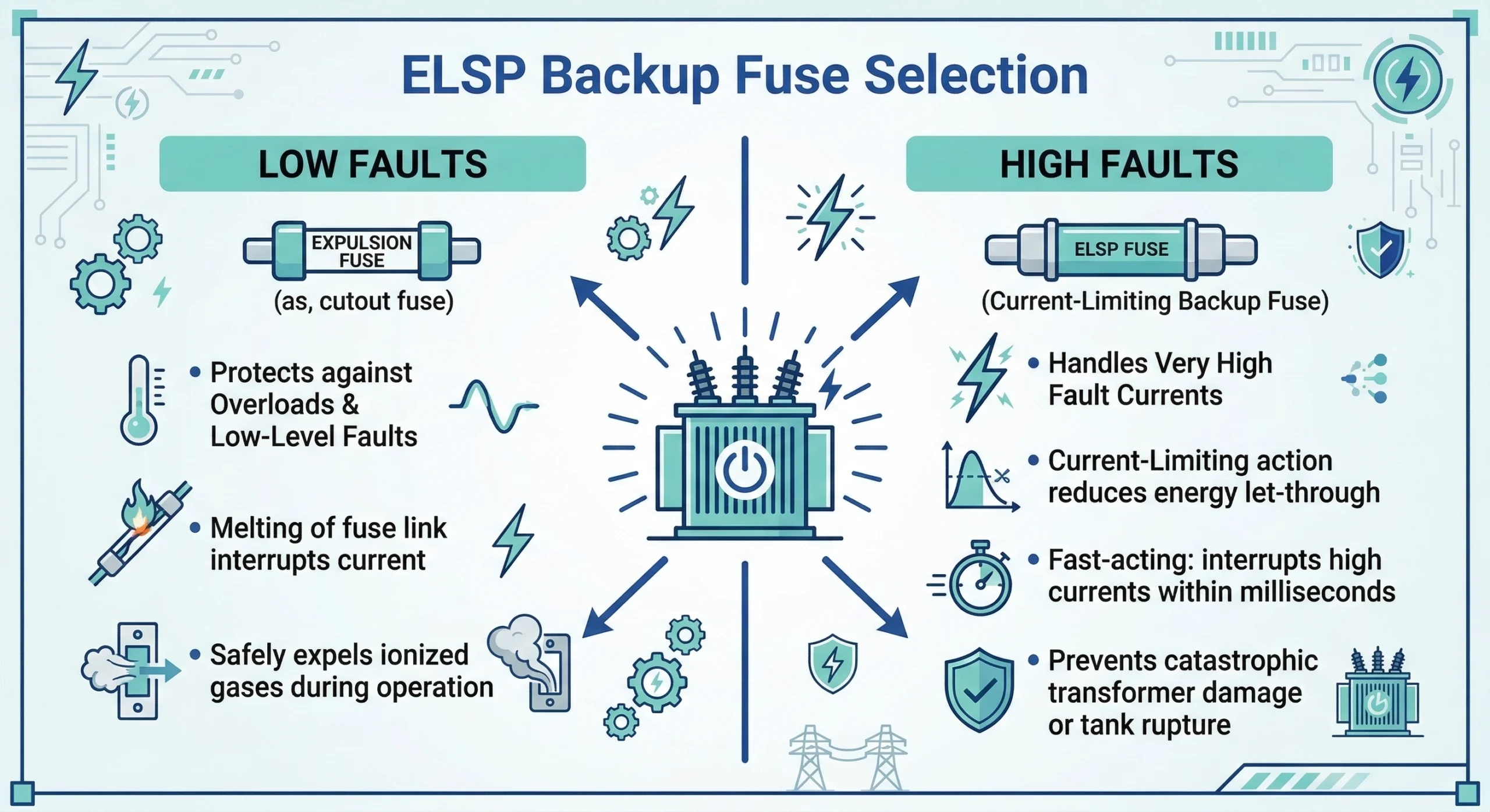
An ELSP fuse is a specialized, partial-range current-limiting fuse designed specifically for under-oil installation inside distribution transformers. Its primary function is to act as the ultimate backup protection, intervening only during high-magnitude internal faults that exceed the interrupting capabilities of the transformer’s primary expulsion fuse. By design, an ELSP fuse cannot clear low-level overload currents; it relies completely on a series-connected device to handle minor system anomalies.
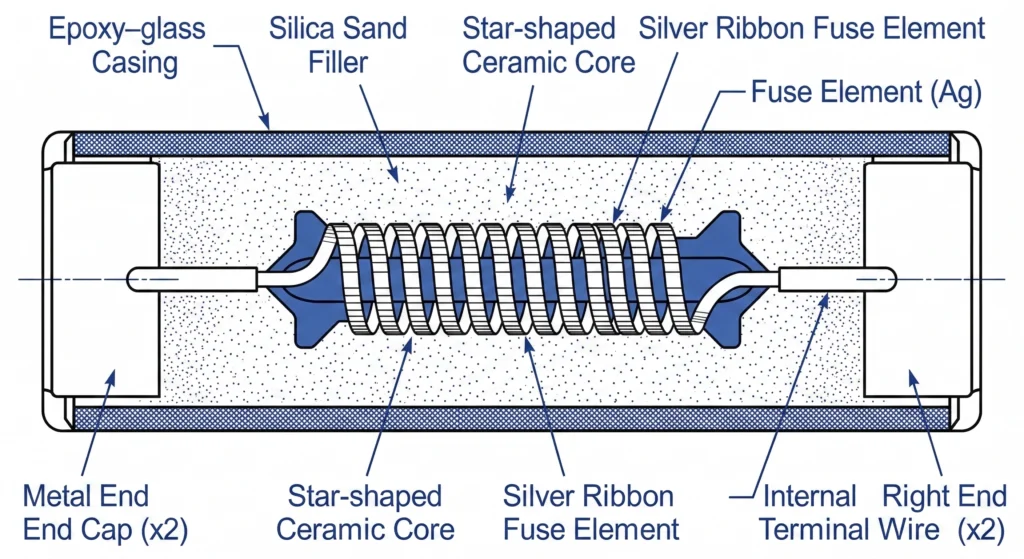
FIG-01:Cross-sectional diagram of an ELSP fuse highlighting the silver ribbon, ceramic core, and compacted silica sand.
Physical Construction and Materials
The internal architecture of an ELSP fuse dictates its high-performance dielectric and thermal characteristics. The outer casing is typically constructed from a filament-wound, epoxy-glass tube that provides mechanical strength and withstands the hydraulic pressures of the surrounding transformer oil. Inside, the active component is a precisely notched silver ribbon element. This element is carefully wound around a star-shaped ceramic or high-temperature synthetic core and entirely packed with high-purity, highly compacted quartz silica sand.
From a field perspective, ensuring the hermetic seal of the end caps is critical before installation inside the transformer tank. If transformer oil breaches the seal and saturates the silica sand over years of service, the fuse’s interrupting capability is severely compromised, risking catastrophic failure during a fault event. For engineers specifying for distribution projects, verifying the sealing integrity under expected continuous top-oil temperatures (often up to 105°C during peak loads) is a standard procurement check.
The Current-Limiting Mechanism
When a severe bolted fault occurs—sometimes reaching symmetrical currents of 50,000 A—the ELSP fuse operates in a fraction of a cycle. The immense thermal energy causes the narrow notched sections of the silver ribbon to vaporize almost instantaneously, creating multiple internal arcs. The surrounding silica sand immediately absorbs this arc energy, melting and fusing with the silver vapor to form a highly resistive glass-like compound known as fulgurite.
This rapid introduction of resistance forces the fault current to zero before it can reach its first asymmetrical peak. By drastically limiting the total let-through energy (often denoted as I2t) and interrupting the circuit in ≤ 8.33 ms (a half-cycle at 60 Hz), the ELSP fuse prevents the transformer tank from rupturing under extreme electromechanical stress.
This operational physics aligns closely with fundamental guidelines set by [NEED AUTHORITY LINK SOURCE: IEEE Std C37.47 for high-voltage distribution class current-limiting fuses], which defines the specific testing parameters for partial-range current-limiting behavior in liquid-immersed applications.
Expert Insight: Internal Fuse Handling and Inspection
Vibration Sensitivity: The highly compacted silica sand inside an ELSP fuse can shift during rough transit. Always inspect the fiberglass casing for hairline stress fractures before under-oil installation.
Seal Verification: Even microscopic breaches in the hermetic end-cap seals will draw in dielectric fluid under vacuum filling processes, permanently degrading the fuse’s I2t arc-quenching capability.
Continuity Testing: Always perform a low-voltage micro-ohm continuity test prior to tanking; a dropped fuse can suffer a severed silver element without showing external damage.
2. The Two-Fuse Protection Scheme: Coordination Logic
Transformer protection requires two fuse technologies working in sequence to cover the entire spectrum of potential electrical anomalies. Relying solely on a partial-range ELSP fuse is an engineering critical error, as these devices cannot safely interrupt low-level overcurrents. Instead, they must be deployed alongside a primary expulsion device to form a complete, coordinated protection scheme.
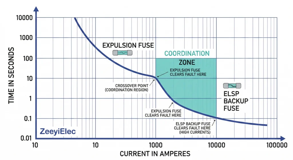
FIG-02:TCC curve overlay demonstrating the crucial non-intersection point between primary and backup fuses.
Expulsion Fuse Zone (Low Faults)
The primary line of defense in an oil-filled distribution transformer is typically a replaceable expulsion device, such as . These fuses are specifically engineered to sense and clear low-to-moderate secondary faults and severe system overloads. In a standard application, the expulsion fuse manages fault currents up to approximately 3,500 amperes. When an overcurrent occurs within this lower range, the expulsion fuse element melts, generating an arc that interacts with the surrounding oil or arc-quenching material to extinguish the fault safely.
ELSP Current-Limiting Zone (High Faults)
When a fault breaches the interrupting capacity of the expulsion fuse—such as a primary internal bolted fault—the ELSP backup fuse takes over. These catastrophic events can generate currents spiking to tens of thousands of amperes within milliseconds, sometimes exceeding 50,000 amperes. The ELSP current limiting fuse is engineered to operate so rapidly that it interrupts these high-magnitude faults exceeding the expulsion fuse’s threshold within a half-cycle. This rapid intervention limits the peak mechanical and thermal stresses, preventing catastrophic tank rupture, oil fires, and severe collateral equipment damage.
The Intersection Point (Melt Curve Coordination)
The successful operation of this two-fuse system relies entirely on the precise alignment of their respective Time-Current Characteristic (TCC) curves.
Engineers must ensure that the maximum interrupting rating of the expulsion fuse (often denoted as Imax_exp) is strictly ≥ the minimum melting current (Imin_melt) of the ELSP backup fuse. The exact crossover point—where the ELSP curve intersects and drops below the expulsion fuse curve—must occur at a current level that both devices can safely handle.
If the crossover point is miscalculated and the ELSP fuse is forced to operate below its minimum interrupting rating, the thermal energy will fail to generate sufficient arc-quenching fulgurite. This leads to a sustained internal arc and the eventual destruction of the fuse housing.
3. Critical Parameters for ELSP Fuse Selection
Selecting an ELSP backup fuse requires matching multiple parameters simultaneously to the transformer’s specific electrical characteristics and the wider distribution network. An improper specification can lead to premature melting during normal operation or failure to interrupt a catastrophic event. Specifying these demands a systematic evaluation across three primary operational boundaries.
System Voltage and Maximum Design Voltage
The voltage rating of an ELSP fuse must strictly align with the system’s maximum operating voltage. Unlike some electrical components, current-limiting fuses are highly voltage-sensitive. If a fuse rated for 15 kV is applied on a 25 kV or 35 kV system, it will fail to clear the fault because the internal arc length will not generate sufficient resistance to halt the current flow. Conversely, significantly over-sizing the voltage rating can cause excessive arc-voltage generation during interruption, potentially exceeding the Basic Insulation Level (BIL) and damaging the transformer’s internal windings.
Transformer Rated Current and Overload Capacity
During normal operation, load currents typically measure in the tens or hundreds of amperes. Because the ELSP fuse is strictly a backup device, it must never operate under these conditions. Engineers must determine the transformer’s Full Load Amperes (FLA) and account for acceptable short-term emergency overloads, which can often reach 150% to 200% of the base rating depending on utility practices. The continuous current rating of the selected ELSP fuse must exceed these peak operational profiles, factoring in the elevated ambient dielectric oil temperatures (often exceeding 90°C under load) which naturally derate the component’s thermal carrying capacity.
Maximum Available Fault Current
During a severe bolted fault, currents can spike to thousands or tens of thousands of amperes within milliseconds. The fuse’s maximum interrupting rating must be rigorously evaluated against the network’s maximum available short-circuit current to prevent explosive equipment failure.
The chosen ELSP fuse must feature a tested maximum interrupting rating (frequently up to 50,000 A symmetrical) that is strictly ≥ the maximum prospective fault current at the transformer’s primary terminals. Furthermore, the fuse’s minimum melting current (Imin_melt) dictates the lower boundary of its effective operational zone. If the device is forced to operate at currents ≤ its stated Imin_melt, it risks severe thermal degradation without achieving the full arc-quenching fulgurite formation required for safe interruption.
Expert Insight: Avoid Common Specification Traps
Do Not Upsize Blindly: Selecting a backup fuse with an excessively high continuous current rating pushes the minimum melting point higher, potentially creating a dangerous “dead zone” between the expulsion fuse’s capability and the ELSP’s activation point.
Account for Oil Temperature Derating: An ELSP fuse rated for 100 A at 25°C ambient air may only safely carry 75 A when submerged in 90°C top-oil. Always request the manufacturer’s thermal derating charts.
Verify BIL Compatibility: Ensure the peak arc voltage generated by the ELSP fuse during clearing does not exceed the lightning impulse withstand capability of the transformer’s internal insulation.
4. Step-by-Step Sizing Logic for Transformer Applications
Procurement engineers and system designers rely on a structured evaluation framework to correctly size ELSP backup fuses. Following a rigorous step-by-step logic prevents specification gaps before they become project delays and ensures reliable two-stage protection.
Step 1: Establish Transformer Full-Load Current (FLA)
The foundation of fuse selection begins with determining the transformer’s maximum operational current. Calculate the base Full-Load Amperes (FLA) using the nameplate kVA rating and primary system voltage. For instance, a 1500 kVA, 12.47 kV three-phase distribution transformer yields a base FLA of approximately 69.4 A. However, field experience dictates that sizing based strictly on base FLA often leads to nuisance melting during routine operations. Engineers typically apply a multiplier of 1.5 to 3.0 to this baseline, creating a functional safety margin that safely accommodates transient magnetizing inrush currents during energization and acceptable short-term peak overloads.
Step 2: Select the Primary Expulsion Fuse
Before specifying the backup device, the primary low-fault protection must be firmly established. Choose an expulsion fuse sized to carry the adjusted FLA derived in Step 1. This device acts as the frontline defense, designed to sense and clear low-to-moderate faults up to approximately 3,500 amperes. It is vital that this primary fuse is selected first, as its thermal and operational limits directly dictate the minimum starting requirements for the backup ELSP fuse.
Step 3: Match the ELSP Fuse for High-Fault Interruption
Transformers face fault currents spanning three orders of magnitude. The specified ELSP current limiting fuse must reliably interrupt high-magnitude faults exceeding the expulsion fuse’s threshold within a half-cycle. Specify an ELSP fuse with a continuous current rating that exceeds the primary fuse’s rating, and verify its maximum interrupting capacity safely bounds the network’s worst-case available short-circuit current.
Step 4: Verify Curve Non-Intersection
The final and most critical phase of the selection logic is overlaying the Time-Current Characteristic (TCC) curves of both selected fuses to ensure seamless operational coordination.
Engineers must plot the data to confirm that the maximum clearing curve of the expulsion fuse intersects the minimum melting curve of the ELSP backup fuse at a current level strictly ≥ the ELSP’s proven minimum interrupting rating. If the coordination crossover point occurs at a current level ≤ this required threshold, the ELSP fuse may attempt to clear a moderate fault it is not thermally designed to handle. Adjust the fuse continuous ratings or element configurations until the curves coordinate flawlessly across the entire Δt spectrum.
5. Installation Environments and Field Constraints
While electrical parameters dictate the theoretical selection of an ELSP backup fuse, the physical realities of the transformer tank dictate its long-term survivability. Because these components are fully immersed in dielectric fluid, their field performance is inextricably linked to the surrounding mechanical and thermal environment.
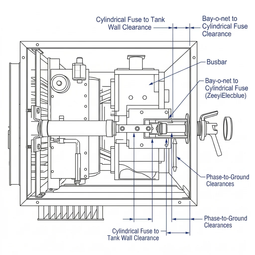
FIG-03:Typical vertical bracket mounting of an ELSP fuse to ensure proper dielectric clearance inside the tank.
Thermal Degradation and Oil Temperature
Unlike externally mounted components, ELSP fuses operate entirely submerged in transformer oil. During peak load cycles, top-oil temperatures routinely exceed 90°C, and under emergency overload conditions, this fluid can reach up to 105°C.
Engineers must account for this extreme ΔT when specifying the fuse’s continuous current rating. Operating continuously at elevated temperatures derates the fuse’s thermal carrying capacity. If the ambient oil temperature is ≥ 90°C, the fuse element experiences accelerated fatigue, reducing its effective continuous rating by up to 20%.
Field experience shows that ignoring this thermal derating is a primary cause of premature nuisance melting, particularly during summer peak-load months when the transformer cooling system is already stressed. Selecting a fuse with a robust thermal margin prevents these costly, highly invasive field failures.
Mounting Clearances and Orientation
Physical installation within the crowded transformer tank requires strict adherence to dielectric clearance rules. The ELSP fuse must be securely bracketed to the internal framework to work in series with the primary bay-o-net device.
To maintain the transformer’s Basic Insulation Level (e.g., a 125 kV BIL on a 25 kV system), the installed fuse must maintain adequate physical separation from the grounded tank walls, the active core, and other phase leads. A minimum clearance of 50 mm to 75 mm is standard practice for 15 kV class applications. Furthermore, the fuse should be mounted vertically or at a steep downward angle. This orientation prevents trapped air or moisture bubbles from accumulating along the epoxy-glass casing, which could compromise the external dielectric strength and lead to tracking or flashover along the fuse body.
6. Specifying ELSP Fuses for Your Next Project
Selecting the correct partial-range current-limiting fuse requires rigorous evaluation. A mismatched component risks catastrophic failure under oil, while a correctly specified ELSP fuse ensures your distribution transformer operates safely for its intended 25 to 30 year service life. When finalizing your engineering specification or Request for Quotation (RFQ), ensure your procurement package clearly defines these operating boundaries to guarantee an exact match.
Essential Procurement Checklist
Specify the system voltage class and Basic Insulation Level (e.g., 15 kV class, 95 kV BIL).
Define the transformer full-load continuous current, including maximum emergency overload profiles.
State the network’s maximum available symmetrical fault current.
Provide the specific Time-Current Characteristic (TCC) curves for the intended primary expulsion fuse.
Detail the ambient top-oil temperature extremes (typically peaking around 105°C during summer load cycles).
ZeeyiElec provides rigorous quality control and direct engineering support to verify these critical parameters before manufacturing begins. Whether you are coordinating internal protection for a 1500 kVA pad-mounted unit, integrating a into a complex distribution network, or sourcing complete for substation interconnections, our technical team ensures seamless system integration. We deliver fast technical responses and comprehensive export documentation, directly preventing the 2 to 4 week procurement delays often caused by incomplete specifications.
Contact our engineering department with your system’s required Imax and operational ΔT to receive a validated ELSP fuse match, technical sizing support, and a competitive quotation today.
Frequently Asked Questions
Can an ELSP fuse be used as a standalone protective device?
No, ELSP backup fuses are strictly partial-range current-limiting devices and must always be used in series with a primary expulsion fuse designed to clear low-level overloads. Relying on an ELSP fuse alone outside its designed high-fault spectrum risks severe thermal failure and internal arcing during minor overcurrent events.
What is the typical lifespan of an oil-immersed ELSP fuse?
Under normal operating conditions within a sealed distribution transformer tank, these fuses are designed to last the lifetime of the transformer, which is typically 20 to 30 years. However, repetitive extreme inrush currents or prolonged operation at elevated top-oil temperatures exceeding 90 degrees Celsius can accelerate silver element fatigue and significantly reduce this expected lifespan.
How do I know if an internal ELSP fuse has blown?
Because they are mounted internally under dielectric oil, direct physical inspection is impossible without draining the tank or pulling the active core. A blown ELSP backup fuse is usually diagnosed via continuity testing across the primary high-voltage bushings after the transformer has been safely isolated and entirely de-energized.
Can I replace a blown ELSP fuse in the field?
Field replacement is highly complex and generally not recommended, as it requires untanking the transformer core or significantly draining the dielectric fluid to safely access the internal mounting brackets. In most practical field scenarios, a blown backup fuse indicates a catastrophic internal transformer fault that necessitates a complete unit replacement or a major factory overhaul.
What happens if the ELSP fuse continuous rating selected is too low?
An undersized backup fuse with a continuous rating below the transformer’s peak overload profile will operate prematurely during routine temporary overloads or standard magnetizing inrush currents. This sizing error results in unnecessary nuisance outages and requires highly invasive, costly internal tank repairs to replace the improperly specified component.
yoyo shi
Yoyo Shi writes for ZeeyiElec, focusing on medium-voltage accessories, transformer components, and cable accessory solutions. Her articles cover product applications, technical basics, and sourcing insights for global electrical industry buyers.