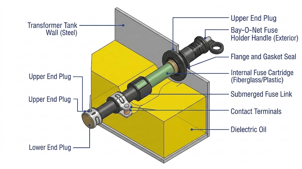
A Bay-O-Net fuse assembly is a dead-front, externally removable overcurrent protection device designed exclusively for oil-immersed distribution transformers. Mounted directly through the transformer tank wall, it physically suspends a replaceable fuse cartridge deep into the internal dielectric fluid. This architecture leverages the transformer’s internal insulating oil to act as both an electrical insulator and a dynamic arc-quenching medium during a fault event. Before the primary power is routed through internal windings via cable accessories, the Bay-O-Net stands as the first line of defense against secondary overloads.
The name “Bay-O-Net” originates directly from its mechanical locking mechanism. The internal fuse cartridge engages with the outer housing using a physical push-and-twist bayonet motion. This locking action compresses an internal gasket, ensuring a secure, pressure-tight seal against the transformer tank while still allowing quick mechanical release via an insulated hot-stick tool. As one of the most foundational transformer accessories specified for pad-mounted systems, the device serves dual functions: detecting slow-building thermal overloads and interrupting low-magnitude secondary faults. Furthermore, its “dead-front” classification guarantees that all external physical touch points are fully insulated, shielding utility operators from live high-voltage components during field inspections.
Electrical and Thermal Parameters
Standard Bay-O-Net configurations are engineered for 15 kV, 25 kV, and 35 kV medium-voltage distribution networks. A standard 15/25 kV class assembly typically features a Basic Impulse Insulation Level (BIL) of 150 kV, ensuring robust dielectric resilience against transient lightning strikes and switching surges. While the continuous load current carrying capacities generally remain ≤ 140 A, the internal fuse elements are uniquely designed to be dual-sensing.They react to both electrical overcurrent magnitude and the ambient temperature of the surrounding transformer fluid. If the internal oil temperature approaches critical insulation degradation thresholds—often exceeding 105 °C to 140 °C depending on the fluid chemistry and load profile—a specialized eutectic alloy within the fuse link melts. This thermal response de-energizes the secondary circuit before catastrophic core damage or tank rupture can occur.
The material construction and sealing integrity of these assemblies must strictly align with design specifications established by [NEED AUTHORITY LINK SOURCE] IEEE C57.12.28 standard for pad-mounted equipment enclosure integrity, ensuring that the fluid boundary maintains an absolute hermetic seal across decades of extreme thermal cycling and internal pressure fluctuations.
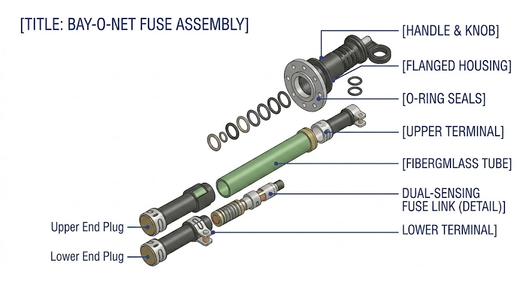
Core Anatomical Components of the Bay-O-Net Assembly
Figure 01:The Bay-O-Net assembly consists of a rigidly mounted outer housing, a fiberglass cartridge, and a replaceable, dual-sensing fuse element.
The Outer Housing and Sealing Mechanism
The primary interface between the transformer’s internal environment and the external world is the Bay-O-Net outer housing. This component is rigidly mounted through the transformer tank wall, typically constructed from high-temperature engineering plastics or specialized molded epoxies designed to withstand continuous exposure to dielectric oils up to 140 °C. The sealing integrity relies on precisely machined grooves holding elastomeric O-rings—often composed of Nitrile or Viton depending on the specific ester or mineral oil used—compressed between the tank wall and the housing flange. A critical design feature is the pressure relief mechanism built into the external cap; before a technician can physically extract the inner cartridge, turning the cap partially vents any built-up internal tank pressure (which can routinely exceed 5–8 psi depending on the transformer’s loading and ambient temperature), preventing a hazardous outward surge of hot oil.
The Inner Fuse Holder (Cartridge)
The internal cartridge—the physically removable portion manipulated by a hot-stick—acts as the mechanical carrier for the fuse element. This holder extends deeply into the transformer fluid, ensuring the fuse link remains fully immersed in the dielectric medium. The cartridge tube is typically manufactured from fiberglass-reinforced composites or high-temperature nylon (HTN). These materials are chosen not just for their mechanical rigidity under the stress of extraction, but for their non-tracking dielectric properties and ability to resist carbonization during an internal arcing event. The lower section of the holder features contact fingers or a threaded interface that mechanically secures the replaceable fuse link and provides a low-resistance electrical path to the lower stationary contacts inside the outer housing.
The Sensing Element (Dual-Sensing vs. Current-Sensing)
The core protective component is the replaceable fuse link itself, available primarily in two configurations for modern bay-o-net fuse assemblies: current-sensing and dual-sensing.
Current-sensing links operate on traditional silver or copper elements designed to melt strictly based on the I2R heating of an overcurrent event. Conversely, dual-sensing links incorporate a specialized eutectic alloy segment placed in series with the main conductive element.This eutectic segment is highly sensitive to the ambient fluid temperature. If a slow, sustained overload condition causes the transformer oil temperature to exceed safe operating limits (e.g., rising above 105 °C to 145 °C), the ambient heat combined with the localized I2R heating of the load current melts the alloy. This dual-action response provides crucial secondary thermal protection for the transformer insulation system, reacting to conditions that a standard current-only fuse might ignore until catastrophic insulation failure initiates a bolted fault.
[Expert Insight]
Gasket Degradation: Field data indicates that 60% of external oil leaks on pad-mounted transformers originate from Bay-O-Net O-rings that have lost elasticity after 15+ years of thermal cycling.
Fluid Compatibility: Upgrading a transformer from standard mineral oil to natural ester fluids (like FR3) requires verifying that the Bay-O-Net’s HTN cartridge and Nitrile seals are chemically compatible to prevent swelling.
Carbon Tracking: Reusing a fiberglass cartridge that has experienced multiple high-energy fault clearances increases the risk of internal carbon tracking, potentially degrading the 150 kV BIL rating.
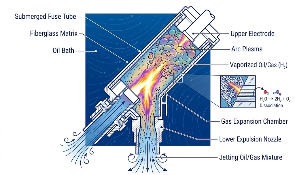
Operating Mechanism: How the Bay-O-Net Fuse Quenches Faults
Figure 02:During a fault, vaporized dielectric fluid creates a high-pressure expulsion wave that aggressively elongates and quenches the electrical arc.
Thermal Overload Detection
When a distribution transformer experiences a secondary fault or a severe, sustained overload, the current flowing through the Bay-O-Net fuse element generates rapid I2R heating. Because the fuse cartridge is fully submerged, there is a continuous thermal exchange between the internal fuse link and the surrounding dielectric fluid. However, when the magnitude of the fault current produces heat faster than the oil can dissipate it, the metallic element’s core temperature spikes. For dual-sensing links, the precisely calibrated eutectic alloy melts, physically parting the circuit. This melting phase typically initiates when localized fluid temperatures exceed 140 °C during severe overload conditions.
The physical separation of the fuse element does not instantaneously stop the flow of electricity. Instead, the circuit voltage immediately bridges the newly formed gap, ionizing the localized environment and striking a high-energy electrical arc.
The Fluid-Expulsion Arc Quenching Process
The successful interruption of the fault relies entirely on fluid dynamics and the expulsion principle. The instant the arc strikes, its extreme thermal energy vaporizes the immediate surrounding transformer oil.
This rapid vaporization creates a highly localized, high-pressure gas bubble—composed primarily of hydrogen and light hydrocarbon gases. The fiberglass or high-temperature plastic cartridge tube plays a critical structural role here: it confines these expanding gases, directing the high-pressure wave linearly. This expulsion force violently pushes the vaporized oil and ionized plasma out of the arc path, aggressively elongating the arc and exposing it to the cooling effects of the surrounding bulk oil, which typically maintains a safer operating temperature of 65 °C to 85 °C.Because the power grid utilizes an alternating current (AC) waveform, the fault current naturally drops to zero every half-cycle (occurring approximately every 8.33 ms in a standard 60 Hz system, or 10 ms in a 50 Hz system). At this exact “zero-crossing” microsecond, the physical arc extinguishes briefly. The high-pressure, un-ionized cooler oil forcefully collapses back into the physical gap inside the cartridge. This rapid dielectric recovery restores the insulation strength between the parted fuse contacts, permanently preventing the arc from re-striking on the subsequent voltage peak.
Field crews diagnosing a transformer after a fault clearance often observe the physical aftermath of this violent fluid-expulsion process. Drawing an oil sample frequently reveals suspended carbon particles or slight fluid discoloration near the assembly housing, an expected byproduct of arc-vaporized oil. This high-pressure arcing event is precisely why standard operating procedures demand that technicians manually vent the transformer tank pressure before attempting to unscrew the Bay-O-Net cap.
[Expert Insight]
Gas Accumulation: The arc-quenching process inherently generates combustible gases. Repeated fuse operations without tank venting can elevate total combustible gas (TCG) levels, triggering false positives during routine dissolved gas analysis (DGA).
Clearance Zones: The violent expulsion of plasma requires strict internal dielectric clearances. If the Bay-O-Net is positioned too close to the core and coil assembly, the conductive gas bubble can trigger a secondary internal flashover before the oil collapses back into the gap.
Protection Coordination: Pairing Bay-O-Net with Current Limiting Fuses
Clearing Low-Current Faults (The Bay-O-Net Role)
A single protection device cannot safely cover the entire spectrum of potential faults a distribution transformer might encounter. The Bay-O-Net fuse is optimized specifically for low-magnitude overcurrents and slow-building thermal overloads—events such as a secondary short circuit on a residential service drop or a sustained 120% load demand during extreme weather. However, its fluid-expulsion mechanism has physical limitations. If exposed to a massive internal transformer fault (e.g., a primary winding collapse), the explosive vaporization of oil would overwhelm the fiberglass cartridge, potentially rupturing the transformer tank. Because its interrupting rating is typically capped between 1,500 A and 3,500 A depending on voltage class, it must be paired with a backup device.
Interrupting High-Magnitude Faults (The CLF Role)
To provide comprehensive protection, engineering standards require a two-fuse coordination strategy: the Bay-O-Net fuse handles the low-end faults, while current limiting fuses(CLFs) intercept the catastrophic high-end faults. When an internal short circuit triggers a massive fault current—potentially surging to 50,000 A symmetrical within a few milliseconds—the CLF acts instantly.Unlike the fluid-expulsion process of the Bay-O-Net, a current limiting fuse contains the arc entirely within a sealed, silica-sand-filled tube. It melts and quenches the arc within a quarter to a half-cycle, completely cutting off the fault before the energy curve (I2t) reaches the mechanical bursting strength of the transformer tank. This coordination logic ensures that common, low-energy faults are cleared by the easily accessible, field-replaceable Bay-O-Net cartridge, while the CLF remains securely mounted inside the tank to prevent catastrophic equipment destruction during rare primary faults.The time-current characteristic (TCC) curves of both fuses must be strictly plotted during the engineering phase. According to [VERIFY STANDARD: IEEE C57.109 guidelines on transformer through-fault duration], the TCC curve of the Bay-O-Net must remain lower and “faster” than the CLF for any fault current below the Bay-O-Net’s maximum interrupting rating, ensuring it operates first for all secondary faults.
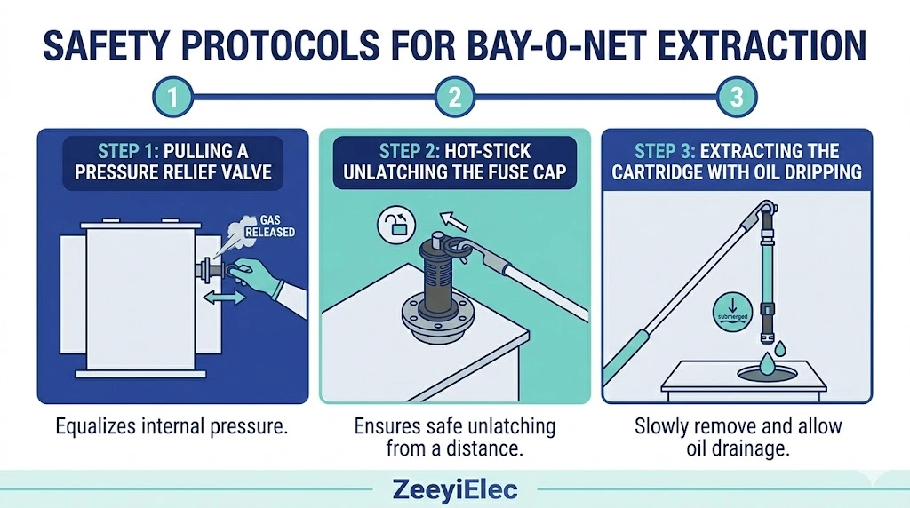
Field Extraction and Hot-Stick Operation Protocols
Figure 03:Safe extraction requires manual pressure venting, unlatching with a hot-stick, and a deliberate pause to allow hot dielectric fluid to drain.
Step 1: Pressure Relief and Venting
Because a Bay-O-Net fuse assembly operates as a sealed barrier between the transformer’s hot internal dielectric fluid and the outside environment, physical extraction is inherently dangerous without proper pressure management. Field technicians must first manually relieve the internal tank pressure before attempting to remove the fuse cartridge. This is typically achieved by pulling the external pressure relief valve (PRV) located on the transformer tank, safely venting the headspace gases to atmospheric pressure (0 psi). Bypassing this step risks the Bay-O-Net cap aggressively blowing outward, propelling hot oil (often measuring 80 °C to 105 °C) at the operator.
Step 2: Mechanical Unlatching with a Hot-Stick
Even after pressure relief, the device is explicitly designed for remote operation using an insulated fiberglass hot-stick. The technician attaches the hot-stick to the eyelet on the Bay-O-Net cap. A firm rotational push-and-twist motion unlatches the bayonet locking mechanism. It is critical at this stage to pause for approximately 5 to 10 seconds; pulling the cartridge out immediately creates a vacuum effect that draws a column of hot oil out of the tank. Pausing allows the internal fluid to drain back through the cartridge housing into the main oil volume, preventing excessive spillage down the transformer sidewall.
Step 3: Extraction and Oil Drainage
Once unlatched and allowed to drain briefly, the technician rapidly extracts the cartridge. The rapid motion is necessary to definitively break any residual electrical connection at the lower contacts and minimize arc tracking if the transformer was recently de-energized or is operating under a light capacitive load. Field crews frequently encounter a small amount of residual oil dripping from the fiberglass cartridge—a normal occurrence given its submersion depth. After extraction, the blown fuse link must be unthreaded from the holder, and the interior of the fiberglass cartridge visually inspected for severe carbonization or structural cracking before inserting a replacement element. Installing a new fuse link requires reversing this exact sequence, ensuring the bayonet mechanism fully “clicks” into its seated position to compress the O-ring seal and restore dielectric integrity.
Engineering Specifications and OEM Procurement
Critical Sourcing Parameters (Voltage Class and BIL)
Procuring the correct protection interface for a distribution transformer requires more than simply specifying a “fuse.” The physical dimensions and electrical ratings of a Bay-O-Net assembly must align precisely with the transformer’s tank design and anticipated short-circuit duty. When developing an RFQ, engineering teams must define the system voltage class (e.g., 15 kV or 25 kV), the required Basic Impulse Insulation Level (BIL) (typically 150 kV for these classes), and the internal tank pressure specifications to ensure the outer housing’s O-ring seals can withstand continuous fluctuations without leaking dielectric oil.
Furthermore, the physical insertion depth of the cartridge must match the internal clearances of the transformer tank; an assembly that is too long risks compromising dielectric clearances to the core, while one too short may fail to fully submerge the fuse link in cooler oil (e.g., below 85 °C) during heavy loading, inadvertently triggering a premature thermal trip.
OEM Support and Requesting a Quote
At ZeeyiElec, our engineering team ensures that every protection component—from Bay-O-Nets to loadbreak switches—matches your project’s precise electrical and mechanical constraints. We support OEM/ODM configurations and provide complete export documentation for international utility and EPC projects. Share your transformer specifications, required fuse ratings, and dimensional drawings with our technical team today.
Contact ZeeyiElec for technical consultation, model matching, and bulk order support to secure reliable transformer accessories for your next distribution project.
Frequently Asked Questions
Can a Bay-O-Net fuse be replaced while the transformer is energized?
While physically designed for hot-stick operation under energized conditions, utility safety protocols generally dictate de-energizing the transformer to prevent drawing a high-energy arc if a secondary fault remains uncleared. If hot-line extraction is permitted by local operating procedures, it is strictly limited by the manufacturer’s load-break capability, which is often capped between 100 A and 160 A depending on the specific model.
What causes a Bay-O-Net fuse to blow frequently?
Frequent tripping typically indicates a chronic secondary overload drawing 120% to 150% of the transformer’s rated capacity, or a scenario where internal oil temperatures consistently exceed 105 °C due to poor pad-mounted enclosure ventilation. Repeated operations may also signal an uncleared, highly resistive low-level fault on the secondary distribution network that continually generates localized heating.
How much oil typically drips during a Bay-O-Net extraction?
If extracted correctly with a standard 5 to 10-second drain pause after unlatching, only a few residual drops (approximately 5 mL to 15 mL) of dielectric fluid should fall from the fiberglass cartridge. Excessive oil spillage usually means the operator bypassed the necessary pause, inadvertently pulling a vacuum column of 80 °C to 100 °C oil directly out of the transformer tank.
What is the maximum voltage rating for standard Bay-O-Net assemblies?
Standard commercial assemblies are engineered strictly for medium-voltage distribution systems, predominantly rated for 15 kV, 25 kV, or 35 kV applications with a standard Basic Impulse Insulation Level (BIL) of 150 kV. They are not deployed in sub-transmission networks exceeding 38.5 kV due to the physical and dielectric limitations of fluid-expulsion arc quenching at extreme voltages.
How do you test a Bay-O-Net fuse element in the field?
Field verification primarily relies on a basic continuity test using a digital multimeter set to measure resistance (Ω); an intact metallic element will display near-zero resistance. However, technicians cannot field-test the precise thermal degradation of the eutectic alloy, meaning any dual-sensing fuse subjected to severe, prolonged over-temperature conditions should be preemptively replaced to ensure reliable future operation.
yoyo shi
Yoyo Shi writes for ZeeyiElec, focusing on medium-voltage accessories, transformer components, and cable accessory solutions. Her articles cover product applications, technical basics, and sourcing insights for global electrical industry buyers.