Selecting the correct is an exercise in thermal management. While medium voltage components—like —are designed primarily to contain dielectric stress and prevent tracking at 12kV to 36kV, secondary side components operating between 1.2 kV and 3.0 kV must be engineered to survive massive, continuous thermal loads. In field inspections, premature bushing failures on the low-voltage side of distribution transformers rarely stem from voltage surges; they almost exclusively result from sustained thermal overloads that bake the assembly and degrade the structural seals.
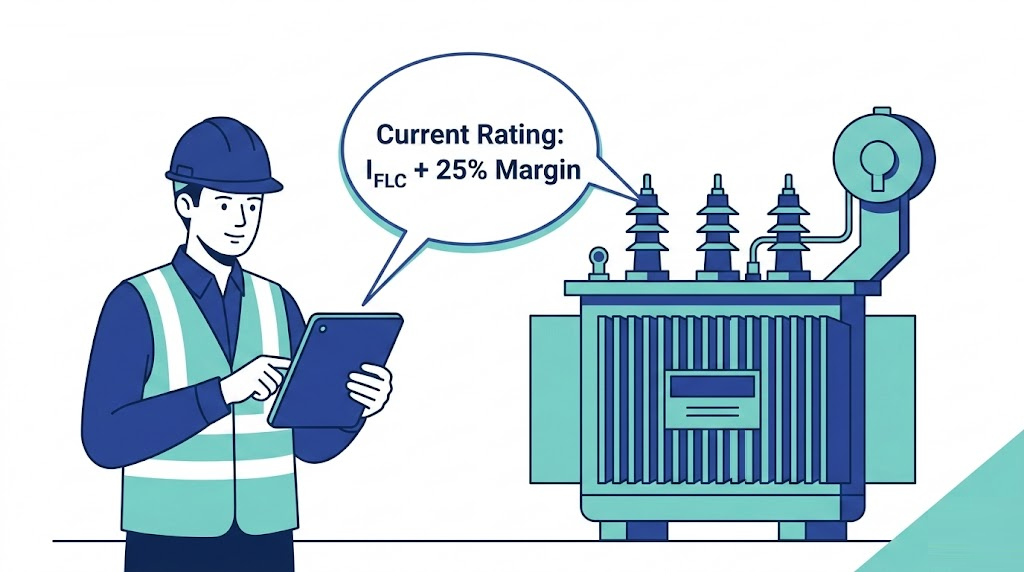
Figure 01:Heat generated by Joule heating (I²R) must safely dissipate through the insulation body to prevent gasket degradation.
Managing Joule Heating and Skin Effect
At the heart of every low voltage bushing is a central conductor stem, typically machined from high-conductivity electrolytic copper or specialized brass alloys. As alternating current flows through this stem, it encounters electrical resistance, generating heat according to the Joule heating formula (P = I2R). When dealing with secondary distribution currents that frequently range from 630A to over 5000A, even a contact resistance of a few micro-ohms (μΩ) translates to significant, continuous thermal dissipation.
Furthermore, alternating current does not distribute uniformly across the conductor’s cross-section. Due to the skin effect at standard 50Hz or 60Hz grid frequencies, current density pushes outward, becoming highest at the outer surface of the stem. As the specified current rating increases beyond 2000A, this effect becomes pronounced, reducing the effective cross-sectional area and increasing the AC resistance (Rac). This physical reality dictates that scaling up a bushing for higher currents requires precise engineering of the conductor’s outer diameter and terminal surface area, rather than simply adding bulk mass to the core.
Thermal Limits and Gasket Integrity
The heat generated by the conductor stem must safely dissipate through the bushing’s external insulation body into the surrounding transformer fluid and ambient air. If a component is undersized for the site’s load profile, the trapped heat will rapidly exceed the thermal index of its sealing system. Standard NBR (Nitrile Butadiene Rubber) gaskets and internal sealing rings are typically rated to tolerate maximum continuous operating temperatures of 105 degrees Celsius to 120 degrees Celsius. Sustained operation above these limits hardens and embrittles the rubber. Once the gaskets lose their elasticity, the transformer tank loses its hermetic seal, opening the door to oil leaks, accelerated moisture ingress, and eventual internal faults.
Step-by-Step Calculation for Secondary Current Rating
Selecting the appropriate capacity for a low voltage bushing requires a rigid mathematical process defined by the transformer’s nameplate data and anticipated load profile. Procurement teams must calculate the exact continuous current requirements before matching them to standard manufacturing tiers.
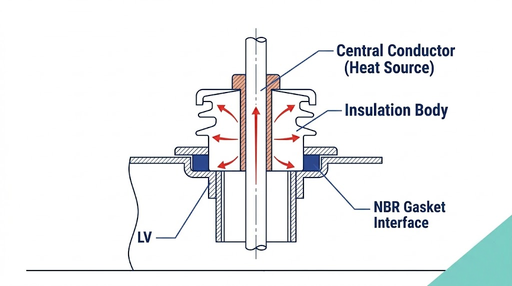
Figure 02:A standard workflow for converting transformer kVA into a required bushing current tier, including mandatory safety margins.
Calculating Full-Load Current (FLC)
The first step is determining the secondary Full-Load Current (FLC), which represents the maximum continuous current the transformer will output under normal operating conditions at its rated power.
For standard three-phase distribution transformers, the fundamental formula is:
IFLC = (kVA × 1000) / (√3 × VL-L)
Where:
IFLC is the Full-Load Current in Amperes (A)
kVA is the rated power of the transformer
VL-L is the secondary line-to-line voltage in Volts (typically 400V or 415V in IEC markets, or 480V in ANSI markets)
For example, if you are specifying transformer accessories for a 1250 kVA unit with a 400V secondary, the calculation is: (1250 × 1000) / (1.732 × 400). This yields a nominal secondary FLC of approximately 1804 Amperes.
Applying the Overload Safety Margin
A common procurement error is specifying a bushing with a current rating exactly matching the calculated FLC. Distribution transformers are routinely subjected to cyclic loading and emergency overload scenarios. According to loading guides like [NEED AUTHORITY LINK SOURCE: IEC 60076-7 Loading Guide for Oil-Immersed Power Transformers], oil-immersed transformers can operate safely above their nameplate capacity for specific durations without immediate catastrophic failure. The associated bushing interfaces must never become the thermal bottleneck during these events.
Standard engineering practice requires applying a minimum safety margin of 20% to 30% above the calculated FLC. Continuing our previous example, applying a 25% safety margin to the 1804A load gives a required target rating of 2255A. In this scenario, a 2000A rated bushing would be at severe risk of overheating and gasket failure during peak summer load cycles. The specifying engineer must round up to the next standard manufacturing size, which is typically a 3150A rated bushing, to guarantee adequate thermal headroom and maintain long-term seal integrity.
[Expert Insight]
Never Round Down: If your calculated FLC plus safety margin is 2050A, do not default to a 2000A standard rating to save minor component costs. The thermal degradation curve accelerates exponentially above rated limits.
Account for Future Upgrades: When specifying accessories for a new substation, sizing the secondary bushings one tier higher (e.g., 3150A instead of 2000A) allows for future forced-air (FA) transformer uprating without requiring a complete tank tear-down to replace undersized bushings.
Mapping to Standard Current Rating Tiers for LV Bushings
Once the continuous secondary current is calculated and an appropriate safety margin is applied, the engineer must map that value to standard manufacturing tiers. Designing a custom-rated bushing for every unique load profile is economically unfeasible and introduces unnecessary supply chain risks. Consequently, manufacturers produce accessories in standardized, high-volume capacity tiers designed to support the complete spectrum of distribution transformers without custom engineering.
Distribution Class Ratings (Up to 1000A)
For standard utility pole-mounted and compact pad-mounted distribution transformers (typically ranging from 15 kVA to 500 kVA), the secondary currents fall within well-defined, lower-tier boundaries. Manufacturers standardize the mechanical interfaces and conductor stem diameters for these applications to streamline installation and reduce inventory complexity.
The most common continuous current ratings specified for distribution class units include:
250A: Routinely utilized on 50 kVA and 100 kVA transformers. These bushings typically feature M12 or M16 threaded stud terminals.
630A: The industry workhorse for 250 kVA to 400 kVA pad-mounted units, generally equipped with M20 or M24 threaded stems.
1000A: Specified for mid-range distribution transformers up to 800 kVA, providing a robust interface for both utility and light-commercial applications.
Selecting a 630A or 1000A standard rating avoids the cost premium and lead times associated with procuring non-standard, low-volume components for routine utility deployments.
Industrial & Power Class Ratings (1000A to 5000A+)
When specifying secondary bushings for heavy industrial, commercial, and utility substation transformers (typically 1000 kVA to 3150 kVA and above), the continuous current ratings escalate rapidly. These environments demand significantly larger conductor cross-sections to manage immense thermal dissipation requirements and prevent mechanical deformation under heavy short-circuit forces.
Standardized current tiers for these power-class applications include:
2000A: Commonly installed on 1250 kVA to 1600 kVA transformers. These bushings often transition away from single threaded studs toward flat, multi-hole spade terminals to accommodate multiple heavy-gauge cable lugs.
3150A: Frequently specified for 2000 kVA and 2500 kVA industrial units. At this rating, managing skin effect and ensuring adequate flat contact area (e.g., NEMA 4-hole or 6-hole pads) is critical.
4000A and 5000A+: Found on the largest distribution and specialized rectifier transformers. These components demand massive, precision-machined copper or brass conductor assemblies and heavily robust epoxy or porcelain insulation bodies.
Selecting the appropriate tier ensures structural compatibility with standard industry cable lugs and busbar connections, preventing costly and dangerous field modifications during commissioning.
Field Conditions That Require Current Derating
A theoretical current calculation assumes ideal, laboratory-grade operating conditions: an ambient temperature of 20°C to 40°C, unrestricted airflow, and perfectly sinusoidal electrical loads. In real-world deployments, these ideal conditions rarely exist. Field engineers must apply derating factors—intentionally reducing the allowable continuous current rating of the component—to compensate for environmental and operational realities that accelerate thermal degradation.
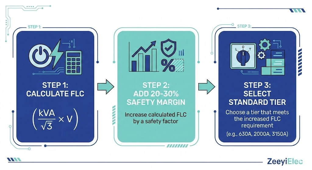
Figure 03:Bushings operating in sealed enclosures or high ambient temperatures require significant capacity derating to survive.
Ambient Temperature and Enclosure Effects
The most common cause of premature secondary bushing failure is trapped heat within the transformer’s low-voltage termination enclosure (the “cable box” or “air terminal chamber”). While the transformer tank itself acts as a massive heat sink, the air inside a sealed, IP54 or IP65 rated enclosure stagnates. If the distribution transformer is installed outdoors in a high-solar-radiation environment (such as the Middle East or the American Southwest), the ambient air temperature inside the sealed enclosure can easily exceed 65°C during peak summer daylight hours.
When the baseline ambient temperature rises, the bushing’s Delta-T (ΔT)—its ability to dissipate its own internal I2R heat into the surrounding air—is severely restricted. Standard [VERIFY STANDARD: IEEE C57.12.00] loading guides generally base continuous current ratings on a maximum ambient air temperature of 40°C. For every 10°C increase above this baseline inside the enclosure, engineers typically apply a derating factor of 5% to 10%. Consequently, a nominal 2000A rated bushing operating in a 65°C enclosure may only possess an effective, safe continuous capacity of approximately 1600A to 1700A. Failing to derate for these enclosure effects leads directly to gasket embrittlement and catastrophic oil leaks.
Managing Harmonics in Industrial Loads
The type of electrical load connected to the transformer also dictates whether derating is necessary. When a distribution transformer supplies power to modern industrial facilities, data centers, or extensive variable frequency drive (VFD) networks, the load profile is heavily non-linear. These loads generate significant harmonic distortion—high-frequency currents superimposed on the fundamental 50Hz or 60Hz waveform.
Because the skin effect is frequency-dependent, these higher-order harmonics (e.g., the 3rd, 5th, and 7th harmonics) push the current density even further toward the outer surface of the bushing’s conductor stem. This dramatically increases the effective AC resistance (Rac) of the copper or brass component, generating substantially more heat than a purely resistive load of the same RMS amperage. When specifying secondary bushings for high-harmonic environments, it is standard field practice to oversize the component by at least one standard rating tier (e.g., selecting a 3150A bushing for a calculated 2000A non-linear load) to ensure the structure can dissipate the excess harmonic heating.
[Expert Insight]
Establish a Thermal Baseline: During site commissioning, conduct an infrared thermography scan of the LV bushings under at least 50% load. Establish a baseline Delta-T between the terminal connection and the surrounding enclosure air.
Monitor the Gasket Interface: The hottest point on a bushing is often hidden inside the tank, but the gasket interface on the exterior wall is the most critical failure point. A temperature rise exceeding 60°C above ambient at the flange indicates immediate severe overloading or internal connection loosening.
Material Selection Based on Thermal Stress and Current
While the central conductor’s cross-sectional area dictates the electrical capacity, the surrounding insulation material determines the bushing’s structural lifespan under continuous thermal stress. Selecting a 3150A rating fails if the insulation body degrades, cracks, or loses gasket compression under the constant heat radiated by the internal stem. Referencing a robust helps engineers systematically evaluate how different insulation materials handle the thermal expansion and physical loading associated with high-current applications.
Porcelain for Standard Utility Applications
Traditional wet-process porcelain remains the dominant insulation material for utility-grade accessories. It offers excellent dielectric strength and is virtually immune to UV degradation in outdoor distribution networks. From a thermal perspective, porcelain easily withstands the baseline 105°C operating temperatures generated by standard 630A to 2000A secondary loads.
However, porcelain is inherently brittle. The primary field failure mode for high-current porcelain bushings is not melting, but mechanical fracturing and seal degradation caused by thermal cycling. As the central copper stem expands and contracts under fluctuating I2R heating, the differing coefficients of thermal expansion between the metal stem, the porcelain body, and the NBR gaskets can gradually loosen the internal fastening hardware. Over a 10-year to 15-year service life, this thermal micro-movement compromises the tank seal, leading to slow insulating fluid weeping on the transformer cover.
Epoxy and HTN for High-Vibration/High-Current Environments
As secondary currents scale from 2000A up to 5000A, the physical weight of the attached copper busbars or multiple heavy-duty 400 mm2 cables increases dramatically. In these high-amperage, high-vibration applications—such as wind turbine step-up transformers, data centers, or heavy industrial plants—engineers increasingly specify cast epoxy resin or High Temperature Nylon (HTN) bushings.
HTN and cycloaliphatic epoxy possess significantly higher tensile and cantilever strength than porcelain. More importantly, they can be molded directly around the conductor stem, eliminating several internal gasket interfaces. These advanced polymers are engineered to maintain structural rigidity at continuous operating temperatures of 130°C to 155°C (Class B or Class F thermal ratings). From a field installation perspective, HTN and epoxy materials allow technicians to safely apply higher fastening torque values—often ranging from 40 N·m to 60 N·m—when bolting massive spade terminals. This higher torque threshold allows for a tighter, more secure connection without the risk of cracking the insulation body, ensuring a low-resistance contact that prevents localized hot spots from developing under peak load conditions.
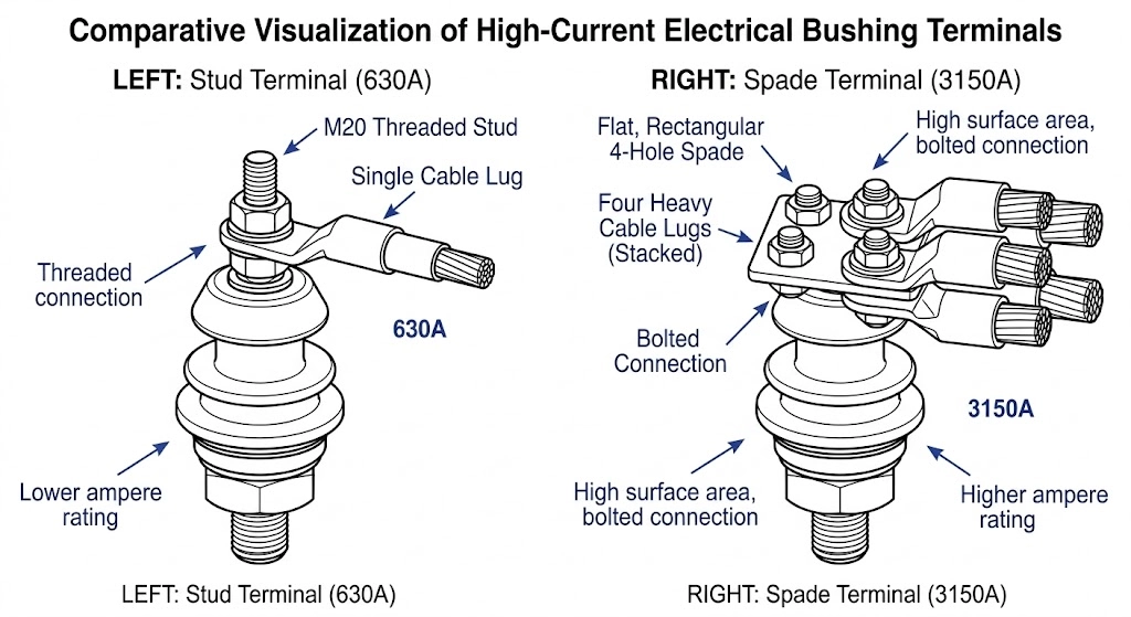
Specifying the Right Terminal Configuration for Your Current Load
The terminal interface—where the transformer’s low-voltage bushing connects to the external distribution network and interfaces with heavy-duty —is the most critical junction in the secondary system. Specifying the correct internal conductor cross-section is irrelevant if the external connection point cannot handle the physical mass or the electrical contact resistance of the attached cables. As continuous current ratings escalate from 250A up to 5000A+, the terminal geometry must shift from simple threaded studs to massive multi-hole spade connectors.
Figure 04:As current loads increase, terminal interfaces must transition from simple threaded studs to large multi-hole spades to manage cable density.
Threaded Stud Interfaces
For lower-tier ratings between 250A and 1000A, the standard interface is a threaded copper or brass stud. This design is highly efficient for single-cable connections in pad-mounted or pole-mounted utility applications.
The diameter of the stud directly correlates with the current carrying capacity:
250A: Typically utilizes M12 or M16 threading, accommodating a single, moderate-gauge cable lug (e.g., 95 mm2 or 120 mm2).
630A: Generally employs M20 or M24 studs, providing the necessary surface area and clamping force for larger single conductors (e.g., 240 mm2 or 300 mm2).
While threaded studs are economical, they rely entirely on the compressive force of a single nut and washer to maintain a low-resistance contact. In field environments subjected to heavy thermal cycling or mechanical vibration, this single point of failure can loosen. A loose 630A connection rapidly develops high contact resistance, leading to localized heating, terminal oxidation, and eventual burn-off. Consequently, technicians must strictly adhere to torque specifications and utilize Belleville washers to maintain continuous contact pressure.
Multi-Hole Spade Connectors
When the calculated secondary current exceeds 1000A, a single cable is no longer physically practical or electrically efficient due to skin effect and routing constraints. Engineers must transition to parallel cable runs or rigid busbars. This requires a transition from threaded studs to flat, multi-hole spade terminals (often referred to as NEMA pads in ANSI markets or standard DIN flags).
These configurations provide the massive surface area required to bolt multiple heavy-duty lugs securely:
2000A to 3150A: These ratings frequently utilize 4-hole or 6-hole spade designs. The flat surface allows technicians to bolt three or four parallel 400 mm2 or 500 mm2 cables directly to the bushing, distributing the current load evenly and minimizing localized hot spots.
4000A to 5000A+: Industrial-class bushings often feature massive 8-hole or even 12-hole spades, engineered to interface directly with extensive copper busway systems or massive parallel cable bundles in substation environments.
Specifying a spade terminal ensures that the bolted connection has sufficient cross-sectional area and contact pressure to safely transfer the extreme continuous currents without exceeding the thermal limits of the bushing’s structural seals.
Procuring Your LV Bushings: Specification Checklist
To prevent costly procurement delays and ensure component compatibility, compiling a complete technical profile before issuing a Request for Quotation (RFQ) is essential. Missing parameters force suppliers to make assumptions, often leading to site-level mismatches that halt installation.
Before reaching out to a supplier or navigating to the for OEM/ODM support, consolidate the following data points:
System Voltage & BIL: Confirm the secondary operating voltage (e.g., 1.2 kV or 3.0 kV class) to ensure the insulation thickness provides adequate dielectric clearance.
Calculated Load + Safety Margin: Clearly define your calculated FLC and your required continuous current rating tier (e.g., 630A, 1000A, 3150A).
Insulation Material Preference: Specify Porcelain, Cast Epoxy, or High Temperature Nylon (HTN) based on your site’s vibration profile and ambient temperature realities.
Terminal Interface Requirements: Determine whether your cable connections demand standard threaded studs (specify M12 to M30) or flat multi-hole spades (specify NEMA pad layout and hole diameter).
Environmental Modifiers: Note if the unit will operate in an IP65 sealed cable box, at altitudes exceeding 1000 meters, or supplying high-harmonic industrial loads.
Bringing a complete specification sheet to your manufacturer guarantees that the delivered bushings will perform reliably across the transformer’s full lifecycle without thermal breakdown.
Frequently Asked Questions
What happens if I select an LV bushing with a current rating exactly equal to the transformer’s full load current?
Selecting a rating without a safety margin leads to severe overheating during standard utility overload cycles or high ambient temperature events. Standard engineering practice dictates adding a 20% to 30% margin above the calculated full-load current to ensure long-term thermal stability and prevent gasket embrittlement.
Does a higher current rating mean the bushing is physically larger?
Yes, higher current ratings require a significantly larger cross-sectional area for the central copper or brass conductor to minimize electrical resistance and associated heat generation. Consequently, the surrounding insulation body and the required mounting hole diameter on the transformer tank cover must also increase to accommodate the bulkier stem.
How do non-linear loads affect my LV bushing current rating selection?
Non-linear loads generate high-frequency harmonic currents that exacerbate the skin effect and dramatically increase I²R heating losses within the central conductor. When supplying heavy industrial variable frequency drives or data centers, engineers typically oversize the bushing by one standard rating tier (e.g., jumping from 2000A to 3150A) to absorb this excess thermal stress safely.
Can I use a 3150A bushing on a transformer that only requires 2000A?
Yes, oversizing a bushing is perfectly safe electrically and provides excellent thermal headroom for the transformer system. However, it requires a larger mounting cutout on the tank and may introduce unnecessary component costs, so it should generally only be done if standardizing inventory or anticipating future transformer load upgrades.
Why do some high-current LV bushings use multi-hole spades instead of threaded studs?
As continuous current ratings exceed 1000A, the physical size and sheer number of parallel cables required to carry the load increase significantly. Multi-hole spade terminals provide the necessary flat surface area to securely bolt multiple heavy-duty cable lugs (such as 400 mm² conductors), ensuring low contact resistance and preventing dangerous hot spots.
Does the installation environment change the required current rating?
While the baseline current rating depends strictly on the electrical load, installations inside unventilated enclosures or in direct solar radiation suffer from elevated ambient temperatures. This higher baseline temperature reduces the bushing’s effective cooling capacity, frequently necessitating a derating factor of 5% to 10% or forcing the selection of the next standard size up to prevent seal failure.
yoyo shi
Yoyo Shi writes for ZeeyiElec, focusing on medium-voltage accessories, transformer components, and cable accessory solutions. Her articles cover product applications, technical basics, and sourcing insights for global electrical industry buyers.