A missing data point in a Request for Quotation (RFQ) does not simply slow down the procurement department; in the context of medium-voltage distribution networks, an incomplete RFQ initiates a costly chain reaction. Industry data reveals that incomplete specifications account for approximately 40% of accessory mismatches and costly change orders during transformer installation projects—delays that add 2–4 weeks to procurement cycles before manufacturing can even begin.
The Procurement Cascade Effect
When an RFQ for medium-voltage bushings lacks critical parameters—such as the specific required creepage distance or the precise terminal thread size—it triggers an immediate administrative cascade. Suppliers are forced to send clarification emails, your internal engineering team must hunt through archived transformer datasheets to verify the missing data, and the initial quotation deadline inevitably slips. Multiply this friction across multiple line items on a substation project, and what should be a standard two-week RFQ cycle easily stretches into six weeks.
Aligning Engineering Specs with Supplier Capabilities
Because transformer accessories serve as critical interface points, they inherently carry a high risk of mechanical or electrical mismatch. Bushings must physically bridge internal transformer insulation with external grid connections. For distribution transformers rated 10–35 kV, accessory compatibility verification typically involves cross-referencing 15–25 distinct parameters before a purchase order can be safely approved.
A bushing that arrives on site with an incompatible mounting flange diameter cannot be modified during installation, resulting in an immediate site rejection. Utilizing a well-structured transformer accessories RFQ checklist directly addresses this vulnerability, translating complex engineering requirements into actionable, error-proof procurement language.
Core Electrical Specifications: The Foundation
The structural integrity of a transformer matters little if the active interfaces cannot handle the continuous electrical stress of the grid. The electrical parameters defined in your RFQ dictate the dielectric thickness, conductor cross-section, and thermal dissipation limits of the required components. Specifying a generic “15kV class” is a starting point, but it is entirely insufficient for a manufacturer to engineer and quote a reliable final product.
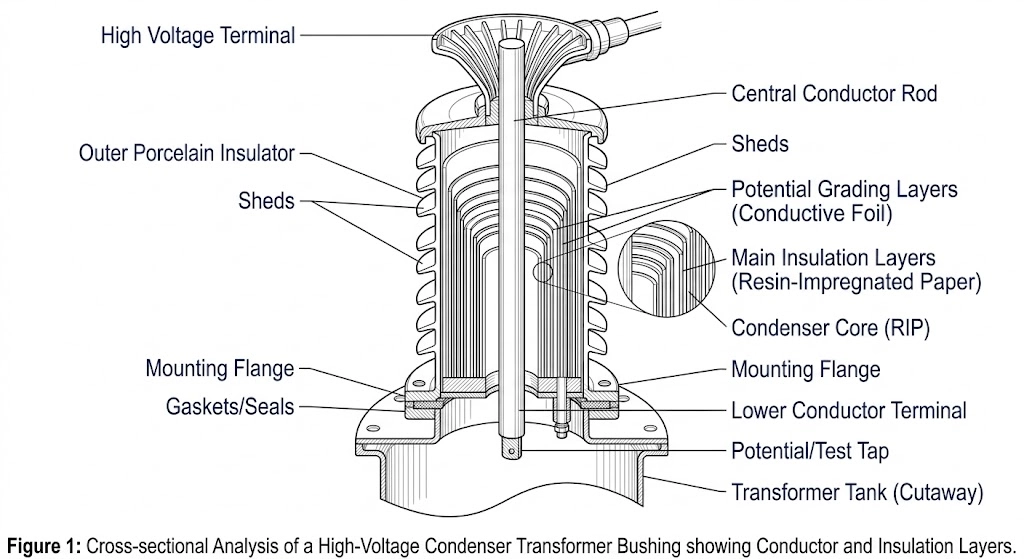
Figure 01:Scientific illustration detailing the internal dielectric stress distribution across the central conductor and mounting flange interface of a high-performance bushing.
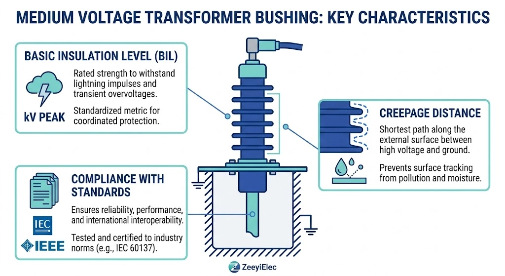
System Voltage and Basic Impulse Level (BIL)
The primary driver of any bushing selection is the operating voltage, which directly determines the required insulation thickness and minimum clearance distances. For distribution and sub-transmission networks, medium voltage bushings must be specified within exact voltage classes, typically ranging from 12kV up to 52kV. However, steady-state voltage is only half the dielectric equation. The Basic Impulse Level (BIL) must be explicitly stated to account for transient overvoltages caused by lightning strikes or grid switching events.
Procurement and design engineers must ensure that the bushing’s maximum equipment voltage (Um) is always ≥ the nominal system voltage. For instance, a 24kV network standardly pairs with a BIL of 125kV. However, overhead networks exposed to severe switching transients often require an elevated BIL (e.g., 150kV) to maintain an adequate dielectric safety margin (ΔV). A mismatch here inevitably leads to insulation puncture under surge conditions.
Continuous Current and Short-Circuit Requirements
Once the voltage class defines the necessary insulation, the continuous current rating dictates the physical size and material of the central conductor. Medium-voltage distribution applications demand a wide operational spectrum, with standard continuous current ratings spanning from 55A for lightly loaded auxiliary transformers up to 3150A for main secondary connections on large pad-mounted units.
Your RFQ must clearly state both the nominal continuous current under maximum ambient temperatures and the required short-circuit withstand capability. During a network fault, the bushing must endure extreme electro-dynamic forces and rapid thermal escalation without structural failure. A properly formatted request will explicitly list the symmetrical short-circuit current and its required time duration (for example, 25kA for 2 seconds). Failing to specify these thermal limits risks procuring a bushing that overheats under peak load, leading to accelerated insulation degradation and eventual oil leaks.
Expert Insight: The Over-Specification Trap
BIL Padding
Adding excessive safety margins to the BIL (e.g., requesting 200kV for a standard 24kV network) unnecessarily inflates the bushing’s physical length, potentially violating your transformer tank’s air clearance limits.
Current Rating Overreach
Rounding up continuous current by more than 20% can trigger a jump to a significantly thicker stud size, forcing a costly redesign of the incoming network cable lugs.
Structural and Material Requirements
While electrical ratings dictate the internal insulation thickness, structural and material specifications determine how the bushing physically integrates with the transformer tank and survives its mechanical operating environment. Overlooking these physical parameters guarantees installation bottlenecks.
Insulation Material Selection (Porcelain vs. Epoxy)
The primary dielectric barrier of a bushing is typically constructed from either traditional electrical-grade porcelain or cast cycloaliphatic epoxy. Porcelain offers excellent surface tracking resistance and proven longevity, but it is inherently brittle, making it susceptible to seismic vibration damage or mechanical impact. Conversely, cycloaliphatic epoxy provides superior flexural strength and allows for more complex, integrated shed profiles. This manufacturing flexibility helps manage capacitive field grading more efficiently in highly compact transformer housings.
When defining the material in your RFQ, you must account for structural weight and cantilever strength. An epoxy bushing can weigh 30% to 40% less than its porcelain equivalent, which directly reduces the mechanical stress exerted on the transformer tank wall. If shifting to a new material profile, reference the structural type-test requirements outlined in the IEC 60137 standard for insulated bushings to ensure the manufacturer validates the dynamic load capabilities.
Mounting Configurations and Terminal Types
The interface between the bushing flange and the transformer tank is a critical zero-tolerance sealing point. Your RFQ must specify the exact flange dimensions, including the bolt circle diameter, hole spacing, and the required gasket compression limits. Field installation teams frequently encounter structural mismatches where a replacement bushing has a flange diameter just 3 mm larger than the original tank cutout. Forcing this fit typically causes gasket shear or induces micro-cracks in the resin base when mounting bolts are torqued ≥ 40 N·m, leading to rapid moisture ingress and oil leaks. Furthermore, the external terminal connection must be explicitly defined. Specify whether the project requires a threaded copper stud, a flat NEMA spade, or a standard clamp-type terminal, ensuring the conductor cross-section (e.g., 250 mm² to 630 mm²) is structurally matched to the incoming network cables.
For a deeper technical review of how physical dimensions and structural materials shift between voltage tiers, consulting a LV Bushing vs MV Bushing: Use-Case Decision Guide can help engineers clarify which terminal architectures are appropriate for their specific transformer design.
Environmental and Field Operating Conditions
A bushing that performs flawlessly during a factory acceptance test can experience rapid dielectric breakdown if deployed in a contaminated field environment without proper design modifications. Specifying the physical site conditions in your RFQ ensures the manufacturer calculates the correct derating factors.
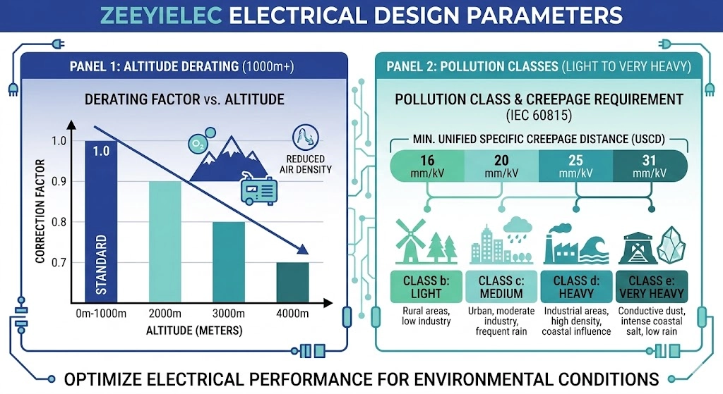
Figure 02:Technical chart mapping the relationship between installation altitude, environmental pollution levels, and the necessary adjustments to bushing creepage and BIL.
Altitude Derating and Creepage Distance
Standard dielectric type tests are conducted assuming an installation altitude ≤ 1000 meters. At higher elevations, the reduced air density lowers the external flashover voltage of the bushing. If a project is located at 2500 meters, such as in high-altitude mining operations, the thinner air requires an altitude correction factor (typically reducing dielectric strength by roughly 1% for every 100 m above the 1000 m baseline). Field commissioning teams frequently encounter scenarios where standard 24kV bushings fail their initial high-voltage withstand tests simply because procurement did not specify the site altitude in the RFQ. To prevent this, your documentation must explicitly state the maximum installation elevation so engineers can appropriately upsize the external arcing distance and structural profile.
Pollution Severity and Temperature Extremes
The severity of airborne contamination—such as coastal salt fog, industrial chemical dust, or desert sand—directly dictates the required specific creepage distance. A standard light-pollution environment may only require 16 mm/kV of creepage, whereas a heavy coastal application demands ≥ 31 mm/kV to prevent surface tracking. In field conditions where morning dew mixes with accumulated industrial dust, underspecified creepage inevitably leads to dry-band arcing and catastrophic flashovers, forcing maintenance crews into unsustainable washing schedules.
Similarly, ambient temperature extremes must be captured. While standard designs operate safely between -25°C and +40°C, deploying equipment in extreme solar-loaded desert environments requires customized internal gasket materials to prevent thermal degradation. When temperature extremes also impact the incoming network connections, engineers must carefully evaluate the entire termination interface, utilizing an engineering selection framework to ensure the chosen cable accessories and bushing terminals experience synchronous thermal expansion without compromising the environmental seal.
Testing, Standards, and Compliance Documentation
Requesting a “fully tested” component in an RFQ is a procurement trap. Manufacturers test to specific regional standard clauses, and failing to define those clauses explicitly means the provided documentation may hold no validity in your local jurisdiction.
Specifying the Correct Regional Standard (ANSI vs. DIN)
The electrotechnical standard governs far more than just electrical withstand; it dictates the physical geometry of the component. Medium-voltage distribution transformers are generally engineered around either IEEE/ANSI standards (dominant in North America) or IEC/DIN standards (dominant in Europe and global export markets).
An RFQ must declare the governing standard definitively because the dimensional profiles are entirely incompatible. For example, a standard 24kV DIN porcelain bushing will feature different mounting hole spacings, stud threading, and oil-side clearance requirements compared to a 25kV ANSI equivalent. Field installation teams frequently encounter scenarios where a replacement bushing electrically matches the network but physically cannot mount to the transformer tank simply because the standard was not defined.
Routine Testing vs. Type Testing Requirements
Your RFQ must clearly distinguish between routine tests and type tests. Type tests validate the fundamental engineering design—such as thermal short-time current tests or mechanical cantilever load tests—and are typically performed once on a representative prototype. Routine tests, conversely, must be performed on every single manufactured unit before it leaves the factory floor.
For medium-voltage components, the RFQ should mandate the submission of certified routine test reports detailing specific dielectric parameters. Chief among these is the partial discharge (PD) measurement. Procurement should explicitly state the acceptable PD limit; for high-reliability distribution systems operating at 24kV, engineers typically demand PD levels ≤ 10 pC at 1.05 times the maximum phase-to-ground voltage. Additionally, power factor (or tangent δ) measurements and dry power-frequency voltage withstand tests (e.g., 50kV for 1 minute) must be documented. If the RFQ does not require these certified reports, field teams risk energizing components with microscopic internal voids that will escalate into insulation failure under load.
Expert Insight: FAT Verification Checks
Demand Original Signatures
Specify that routine factory test reports must be formally signed by the manufacturer’s QA engineer, rather than accepting generic summaries on a commercial packing slip.
Match Serial Numbers
Require that the serial numbers on the test documentation perfectly match the stamped nameplates on the delivered bushings to prevent non-compliant batch mixing.
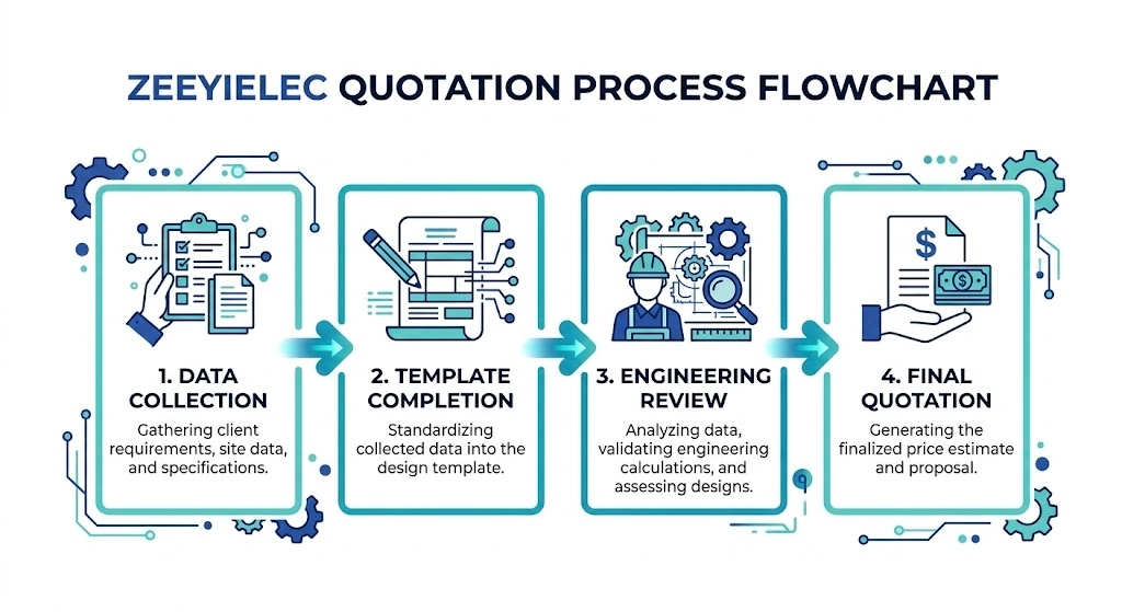
Complete MV Bushing RFQ Template (Copy & Paste)
Translating engineering specifications into procurement documentation requires structured precision. Using a standardized template ensures that your supplier receives all necessary variables to accurately quote the component. You can copy and paste the following parameters directly into your next email or procurement portal.
Figure 03:This workflow defines the efficient path from initial data collection using the RFQ template to final technical validation and manufacturer quotation.
Transformer Data Section
Before defining the bushing, the manufacturer must understand the host equipment. This provides context for thermal dissipation and structural mounting constraints.
Cooling Medium: (e.g., Mineral Oil, Ester Fluid, Dry-type)
Installation Environment: (Indoor vs. Outdoor)
Site Altitude: (Specify maximum elevation in meters)
Pollution Severity Class: (e.g., Light, Heavy, Very Heavy)
Bushing Technical Parameters Section
This section strictly defines the electrical and mechanical tolerances. Ensure your maximum equipment voltage (Um) is explicitly stated, as it dictates the core insulation thickness and external arcing profile. For standard distribution applications, continuous current values typically range from 250A up to 3150A, but the exact requirement must reflect the transformer’s maximum thermal overload rating.
Mounting Flange Type/Dimensions: (Include Bolt Circle Diameter in mm)
Terminal Type: (e.g., Threaded Copper Stud M20, NEMA 4-Hole Spade)
Commercial and Documentation Requirements Section
To prevent compliance issues during site commissioning, define the exact testing and drawing requirements upfront. Each component requires specific technical parameters matched to the transformer’s voltage class and operating environment.
By defining your acceptance criteria—such as demanding a factory partial discharge measurement of ≤ 10 pC—you eliminate low-quality bids and establish a strict quality baseline.
Order Quantity and Target Delivery: (Specify units and lead time)
Required Test Reports: (e.g., Certified Routine Test Reports, Type Test Validation)
Drawing Requirements: (e.g., 2D/3D CAD models required before manufacturing)
Export Documentation: (e.g., Certificate of Origin, specific commercial invoices)
Submit Your RFQ for Engineering Review
Bridging the gap between a project specification and a manufactured component requires rigorous technical scrutiny. Once you have compiled your transformer data and bushing parameters using the template above, the next step is standard verification and component matching. Our engineering team at ZeeyiElec specializes in reviewing these technical matrices to identify any structural or electrical incompatibilities before procurement ever begins.
Whether your project scope is limited strictly to transformer integration or extends out to the network requiring cable accessories for complete distribution connectivity, precise data eliminates field guesswork. We process detailed RFQs for systems ranging from 12kV up to 40.5kV, providing technical evaluation, standard compliance check, and structural drawing verification within 24 to 48 hours.
By submitting your completed parameters—specifically the required continuous current and target BIL—our engineers can immediately cross-reference your demands against our established ANSI, DIN, and cycloaliphatic epoxy product matrices. Send your completed technical template, along with any available tank mounting CAD files, directly to our engineering support desk. We verify that the specified component will physically mount to your unique transformer housing and reliably survive its intended field environment.
Frequently Asked Questions
What is the standard creepage distance for MV bushings?
Standard creepage distance typically ranges from 16 mm/kV for light pollution environments up to 31 mm/kV for heavy coastal or industrial contamination. This must be calculated based on the maximum equipment voltage to prevent surface tracking under wet or contaminated conditions.
How does altitude affect MV bushing selection?
Installations above 1000 meters experience reduced air density, which lowers the dielectric strength of the air and requires the bushing’s external flashover distance and BIL to be derated. Procurement teams must state site altitude so designers can apply correction factors and upsize the insulation profile as needed.
What is the difference between ANSI and DIN standard bushings?
ANSI standards use North American imperial dimensions and connection types, while DIN standards use European metric interfaces and distinct flange geometries. These systems are physically incompatible; a transformer tank drilled for a DIN bushing cannot accept an ANSI equivalent without significant structural modification.
Why must the Basic Impulse Level (BIL) be specified in the RFQ?
The BIL defines the bushing’s peak voltage withstand capability during lightning strikes or network switching transients, which often reach thousands of volts in milliseconds. Specifying only the nominal operating voltage risks procuring a component that will fail during the first high-voltage surge on the grid.
Can epoxy bushings replace porcelain in outdoor applications?
Cycloaliphatic epoxy bushings are suitable for outdoor use and provide superior mechanical strength and lighter weight than porcelain. However, the specific epoxy resin must be UV-stabilized and the shed profile designed for the local pollution class to ensure long-term reliability.
What documentation should accompany a bushing RFQ?
A complete RFQ should include the transformer manufacturer’s tank mounting dimensions, internal lead interface requirements, and the required test standards (IEC or IEEE). Providing these technical drawings upfront prevents clarification delays and ensures the quoted component is ready for immediate production.
yoyo shi
Yoyo Shi writes for ZeeyiElec, focusing on medium-voltage accessories, transformer components, and cable accessory solutions. Her articles cover product applications, technical basics, and sourcing insights for global electrical industry buyers.