A scheduled maintenance window on a medium-voltage distribution network is an unforgiving environment. When a line crew de-energizes a pad-mounted transformer for routine component replacement, they typically operate within a strict 4-hour to 6-hour outage block. Discovering that the newly issued bushing well inserts do not properly mate with the existing transformer wells stalls the entire operation, forcing dispatch to extend the outage and source alternative components. However, an immediate physical mismatch—where the insert simply will not thread in—is actually the best-case scenario. The true cost of incompatibility materializes when a mismatched interface appears successful but harbors hidden defects that go undetected during initial energization.
Latent Defects from Dielectric Voids
When an insert and a well from different manufacturers, or of slightly incompatible dimensional tolerances, are forced together, the primary risk is the formation of microscopic air voids along the mating interface. In a standard 200 A loadbreak system operating at a 15 kV or 25 kV class rating, these trapped air pockets become localized sites of extreme electrical stress. Because the dielectric strength of air is significantly lower than that of the surrounding EPDM rubber, the air breaks down under high voltage. Over a period of 12 to 18 months, continuous partial discharge (PD) inside these gaps erodes the insulation. This electrical tracking inevitably carves a conductive carbon path, resulting in a phase-to-ground flashover that violently destroys the connection and triggers an unplanned outage.
Mechanical Strain and Thermal Runaway
Beyond dielectric breakdown, minor dimensional mismatches introduce severe mechanical and thermal risks. If the internal threaded copper stud of the bushing well does not perfectly align with the insert’s conductive probe, the resulting connection will lack the required surface area and contact pressure. Field experience consistently demonstrates that loose, cross-threaded, or misaligned connections create high-resistance electrical joints. Under a continuous 200 A load, this localized resistance generates excess heat. Because the interface is heavily insulated to contain voltage, this heat cannot effectively dissipate, triggering a thermal runaway condition. Over time, the localized temperature rise melts the surrounding polymer, embrittles the sealing cuff, and risks catastrophic equipment failure.
[Expert Insight]
The “Hiss” Test: Field crews should always listen for a distinct hiss of escaping air when seating an insert. Silence often indicates a lack of proper venting or a premature bottom-out before the vacuum seal forms.
Thermography Baseline: Always conduct an IR scan on newly mated interfaces 48 hours after energization under load to establish a baseline ΔT; abnormal heating reveals micro-gaps invisible to the naked eye.
Zero-Tolerance Threading: If hand-threading a 200A insert requires tool leverage before the final torque phase, stop immediately. The stud is either cross-threaded or mismatched.
Understanding the Interface Anatomy: Well, Insert, and Elbow
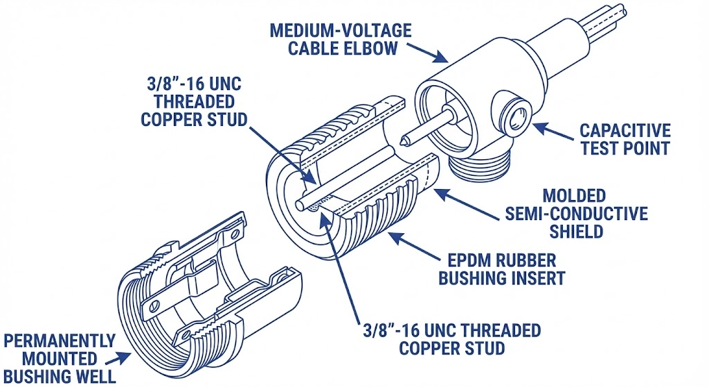
To properly evaluate compatibility, field engineers must understand the multi-layered architecture of a separable insulated connector system. The complete transformer accessories interface functions as a unified assembly where mechanical integrity directly dictates dielectric performance.
Figure 01: The complete 200A separable insulated connector architecture, illustrating the critical dielectric sealing boundaries.
The Bushing Well Foundation
The bushing well serves as the permanently mounted base on the transformer tank wall. At its core is the primary conductive stud—most commonly utilizing 3/8″-16 UNC threads for 200 A distribution systems. When the components are fully seated, the mechanical mating must establish a contact resistance of ≤ 50 μΩ to prevent localized heating under continuous load. The well acts as the critical barrier, isolating the internal transformer oil, which frequently operates at a ≥ 65°C temperature rise, from the external environment.
The Insert Profile
The bushing insert acts as the crucial adapter between the well and the cable elbow. Manufactured primarily from high-quality EPDM (Ethylene Propylene Diene Monomer) rubber, it features an internal conductive probe and a molded semi-conductive shield that extends the system’s ground plane. The exact taper, length, and seating depth of this profile are governed by strict industry guidelines. For North American distribution networks, adherence to [NEED AUTHORITY LINK SOURCE: IEEE 386 Standard for Separable Insulated Connector Systems] is required to establish baseline dimensional interchangeability. Despite these standardized dimensions, micro-tolerances between different OEM molding processes can still introduce field sealing challenges if mixed carelessly.
The Elbow Connection
The loadbreak elbow completes the dead-front system, housing the medium-voltage cable conductor and providing the final external semi-conductive shield. When the elbow is pushed onto the insert, the interface relies on a precise interference fit to displace air and create a watertight, corona-free seal. These elbows frequently integrate capacitive test points, allowing technicians to safely verify system voltage without breaching the primary insulation boundary. The physical interaction between the insert’s locking ring and the elbow’s internal seating groove is the only mechanism securing the connection against the explosive forces of a potential fault or loadbreak operation.
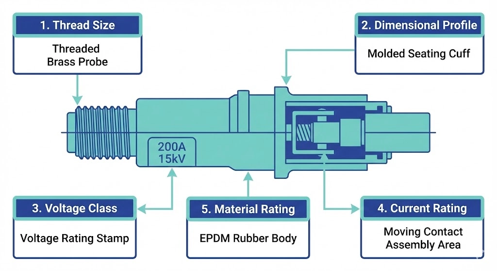
The 5-Point Pre-Installation Compatibility Checklist
Before applying dielectric grease or threading a single component, field engineers must conduct a strict visual and technical verification of the mating parts. Relying on physical force to overcome a mismatch will permanently damage the medium voltage bushings and compromise the surrounding interfaces. Use this five-point checklist to confirm full compatibility prior to installation.
Figure 02: The pre-installation 5-point inspection zones for verifying insert compatibility.
1. Voltage Class Verification (15kV, 25kV, 35kV)
The system’s operating voltage dictates the internal insulation thickness and the required creepage distance. A standard 15 kV class insert typically carries a 95 kV BIL (Basic Impulse Level), while a 25 kV system requires an insert rated for a ≥ 125 kV BIL. Never install a lower-rated insert into a higher-voltage well, as the dielectric boundary will inevitably fail during transient overvoltages or switching surges.
2. Current Rating Match (200A Loadbreak vs. Deadbreak)
Confirm the operational intent of the interface. A 200 A loadbreak system utilizes specialized arc-snuffing materials and a moving contact assembly designed to safely extinguish arcs during live switching operations. Conversely, deadbreak systems (frequently rated at 600 A or higher) lack this internal arc-quenching capability. Mating mismatched current class components or operating a deadbreak interface under load will trigger a catastrophic explosive failure.
3. Thread Size and Stud Inspection
Verify the mechanical linkage between the insert and the primary bushing well. The North American standard for 200 A distribution equipment dictates a 3/8″-16 UNC threaded copper stud. Before mating, meticulously inspect the well’s threads for galling, cross-threading from previous installations, or heavy oxidation, any of which will increase contact resistance and prevent proper seating.
4. Dimensional Profiling
While [VERIFY STANDARD: IEEE 386] governs the broad dimensional and electrical interchangeability of separable insulated connectors, physical profiling remains a critical field step. Check the length of the insert’s molded taper against the internal depth of the well. An insert that bottoms out internally before its sealing cuff fully seats against the well’s outer lip leaves the entire interface vulnerable to moisture ingress.
5. Material and Environmental Ratings
Ensure the EPDM insulation is rated for the specific field environment. For pad-mounted transformers exposed to extreme thermal cycling, the molded rubber must maintain its dielectric and mechanical properties at continuous operating temperatures of ≤ 90°C, with emergency overload ratings accommodating spikes up to 130°C. Always check the manufacturing date code to ensure the rubber has not exceeded its shelf life and become too brittle to form a reliable vacuum seal.
[Expert Insight]
Shelf-Life Awareness: EPDM rubber loses elasticity over time. Never install an insert that has been sitting in non-climate-controlled storage for over 5 years, as its ability to form an interference fit is compromised.
Grease Trap Avoidance: Applying too much dielectric grease creates a hydraulic lock at the bottom of the well, physically preventing the insert from reaching its required dimensional profile depth.
Color-Coded Verification: Utilize manufacturer color bands (e.g., yellow for 25kV, red for 15kV) as a secondary visual check, but always verify the stamped rating on the cuff prior to installation.
Field Verification: Testing for Proper Seating and Sealing
Even with perfectly matched components, the physical execution of the installation dictates the long-term reliability of the connection. Field engineers must rely on a combination of calibrated tools and tactile feedback to ensure the insert fully seats within the well without compromising the internal threads or trapping dielectric voids.
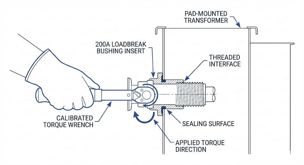
Applying the Correct Torque
Installing the insert requires a calibrated torque tool designed specifically for standard 200 A distribution accessories. The universally accepted torque specification for this interface is 10 to 15 ft-lbs (13.5 to 20.3 Nm). Field technicians must initially hand-thread the insert to feel for the smooth engagement of the 3/8″-16 UNC stud, actively avoiding cross-threading. If resistance is felt before the insert is halfway seated, back it out immediately. Exceeding the maximum torque limit will strip the soft copper threads, forcing a complete replacement of the well assembly and triggering an extended outage.
Verifying the Cuff Seal
Once torqued, the physical seating of the insert’s molded cuff against the well collar must be visually and physically verified. The interface is designed to create an interference fit. A properly seated insert will display no visible gap between its grounding collar and the lip of the bushing well. If a gap remains, it typically indicates that the internal stud has bottomed out prematurely or that debris is trapped in the well chamber. Do not rely on the loadbreak elbow to push a stubbornly unseated insert further into the well during final assembly.
Addressing Trapped Air (Venting)
As the insert is threaded into the well, the tight tolerances of the EPDM rubber act like a piston, trapping ambient air at the base of the chamber. If this air is not evacuated, the resulting pneumatic pressure will physically push back against the threads, reducing contact pressure and creating a dielectric void capable of initiating partial discharge. Field crews must apply a thin, uniform layer of approved silicone dielectric grease (typically applied at ≤ 0.1 mm thickness) to lubricate the interface. Many modern inserts feature a built-in venting channel, but technicians should listen for the distinct “hiss” of escaping air or use an approved venting tool along the collar boundary to ensure the internal pressure reaches 1 atm before applying final torque.
Common Compatibility Failures and Diagnostic Indicators
When a component mismatch bypasses initial quality control, the electrical network inevitably reveals the structural flaw once energized. Field diagnostics rely on identifying these physical and electrical symptoms before a latent defect escalates into a catastrophic ground fault that damages surrounding transformer components.
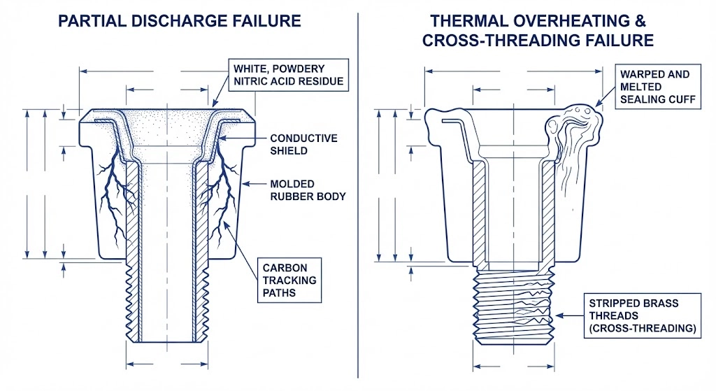
Figure 03: Common failure modes resulting from dimensional mismatch or improper field seating.
Signs of Cross-Threading
Cross-threading is the most frequent mechanical failure during insert installation. If a technician forces a misaligned insert, the harder copper threads of the well stud will shear the brass threads of the insert probe. A key diagnostic indicator during removal is the presence of fine metal shavings at the base of the well. Electrically, this compromised mechanical joint severely reduces the conductive surface area, often pushing the localized contact resistance well beyond the acceptable ≤ 50 μΩ threshold, which inevitably leads to overheating.
Identifying Partial Discharge (PD) Tracking
Partial discharge thrives in the microscopic air voids caused by dimensional mismatches between the well and the insert. Field engineers can often detect early-stage PD through olfactory senses—a distinct ozone odor inside the pad-mounted transformer cabinet. Visually, PD manifests as a white, powdery residue (a byproduct of nitric acid formation) along the EPDM rubber interface. Left unchecked, this degrades into dark, branching carbon tracks across the dielectric surface. Ultrasonic or UHF diagnostic equipment might register PD levels of ≥ 50 pC (picocoulombs) months before a physical flashover occurs.
Thermal Overheating from Poor Contact
A loose or mismatched interface acts as an unintended resistive heater. Under a continuous 200 A load, a high-resistance joint can rapidly exceed the continuous operating rating of 90°C for standard EPDM insulation. Field inspectors utilizing infrared (IR) thermography will spot an abnormal ΔT (temperature rise) on the affected phase compared to adjacent, correctly seated connections. In advanced stages of thermal runaway, the external rubber cuff of the insert will appear warped, discolored, or severely embrittled, permanently destroying the environmental seal and requiring immediate replacement of both mating components.
Standardizing Your Transformer Accessories Procurement
The majority of field compatibility issues stem from a fragmented procurement strategy. When purchasing teams source transformer wells from one supplier, loadbreak inserts from another, and elbows from a third, they force field engineers to manage overlapping dimensional tolerances and varying EPDM shrinkage rates. While these components may claim standard interchangeability, the reality of installation often reveals microscopic gaps that lead to partial discharge and eventual failure.
Standardizing your cable accessories and transformer interfaces through a single engineering-oriented manufacturer eliminates the guesswork at the site level. By matching the dielectric materials, thread profiles, and seating depths directly at the factory, you drastically reduce the risk of cross-threading, thermal runaway, and delayed energization. Field crews can focus on proper torque and seating rather than fighting incompatible geometries.
ZeeyiElec provides fully coordinated MV and LV accessory packages, ensuring your distribution transformer interfaces—from the internal bushing well to the external cable termination—perform as a unified, leak-free system. Contact our engineering team today to discuss OEM/ODM technical matching, request component samples, and secure reliable accessories for your next utility or industrial project.
Frequently Asked Questions
Can I use a 25kV insert in a 15kV bushing well?
Yes, physical fit is sometimes possible due to shared interfaces, but doing so drastically alters capacitive stress grading and can trigger premature insulation breakdown during system switching surges. You must always precisely match the insert’s voltage rating to both the well and the system operating voltage.
What is the standard torque requirement for a 200A bushing insert?
The standard torque is 10 to 15 ft-lbs (13.5 to 20.3 Nm), which ensures proper contact pressure without shearing the internal threads. Exceeding this limit destroys the copper stud, while under-torquing leads to high contact resistance and eventual thermal runaway.
Are all 200A loadbreak inserts universally compatible?
While baseline dimensions conform to industry standards, micro-tolerances in EPDM shrinkage between brands mean that mixing OEMs can slightly reduce the effectiveness of the environmental interference seal over a 20-year lifespan. Matching manufacturers whenever possible provides the highest degree of reliability.
How do I fix a stripped bushing well stud?
Field repair of a stripped stud is impossible; you must drain the transformer oil below the tank interface and completely replace the well assembly to restore structural and electrical integrity. Attempting to force an insert onto compromised threads will always result in a high-resistance fault.
Why is silicone grease required during insert installation?
Applying a ≤ 0.1 mm layer of dielectric silicone grease reduces EPDM friction during seating and actively displaces trapped air. This prevents pneumatic push-back against the threads and eliminates microscopic voids where partial discharge typically initiates.
What is the lifespan of an EPDM bushing well insert?
When installed without cross-threading and operated within its ≤ 90°C continuous thermal limit, a premium EPDM insert reliably functions for 20 to 30 years. However, chronic overloading, severe UV exposure, or chemical contamination will accelerate polymer degradation and significantly shorten this timeframe.
yoyo shi
Yoyo Shi writes for ZeeyiElec, focusing on medium-voltage accessories, transformer components, and cable accessory solutions. Her articles cover product applications, technical basics, and sourcing insights for global electrical industry buyers.