A bushing well insert is a threaded, insulated component that installs directly into a distribution transformer’s primary bushing well. It creates a standardized, shielded interface for connecting medium-voltage underground cables via loadbreak or deadbreak elbow connectors. Essentially, it bridges the transformer’s internal high-voltage coils with the external distribution network while maintaining a fully dead-front safety profile.
Role in the Distribution Network
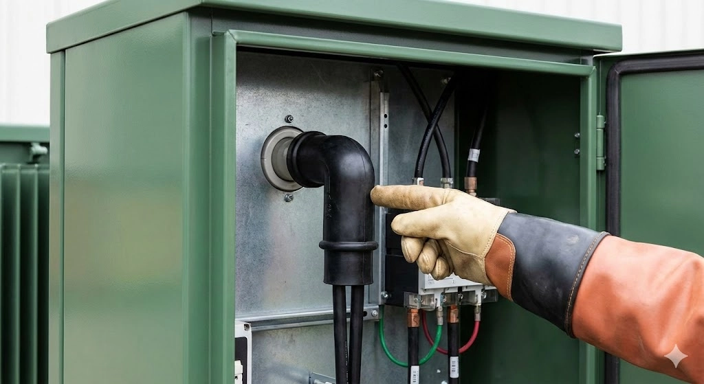
In underground residential and commercial power distribution, pad-mounted transformers require a safe, reliable method to interface with incoming power cables. The bushing well insert serves as this essential junction. The universal bushing well is permanently mounted to the transformer tank wall and wired to the internal active parts. The insert threads into this well, providing the protruding, engineered mating surface required to accept a separable insulated connector.
When evaluating for a site upgrade or new installation, the modular nature of the insert provides a major operational advantage. If the external interface is damaged by a severe fault, transient overvoltage, or mechanical stress, field crews can simply unthread and replace the insert. This prevents the need to open the sealed transformer tank, drain insulating oil, or replace the entire factory-sealed bushing well, effectively reducing an all-day repair into a one-hour maintenance task.
Operational Parameters and Standards
Bushing well inserts are manufactured to match specific system voltages, most commonly deployed across 15 kV, 25 kV, and 35 kV medium-voltage networks. The standard loadbreak configuration is rated for a continuous current of 200 A. To protect the system against transient overvoltages—such as lightning strikes or grid switching surges—inserts are designed to withstand a Basic Impulse Level (BIL) of 95 kV for 15 kV systems, scaling up to 150 kV for 35 kV applications.
The dimensional tolerances, testing protocols, and electrical integrity of these components are strictly governed by [NEED AUTHORITY LINK SOURCE: IEEE Std 386]. This standard dictates the exact interface geometry, ensuring that an insert produced by one manufacturer will seamlessly mate with a bushing well or an elbow connector from a completely different supplier. This guarantees vital interoperability across the North American power grid and international networks adhering to ANSI/IEEE frameworks.
To prevent localized heating and thermal failure under load, the mechanical connection between the insert’s internal copper contact and the well’s threaded stud must maintain an extremely low contact resistance, typically measuring ≤ 50 μΩ. Proper field installation is equally critical; technicians must apply a precise torque, usually between 10 ft-lbs to 15 ft-lbs, to fully compress the environmental sealing rings without fracturing the internal epoxy threads.
Structural Components and Material Design
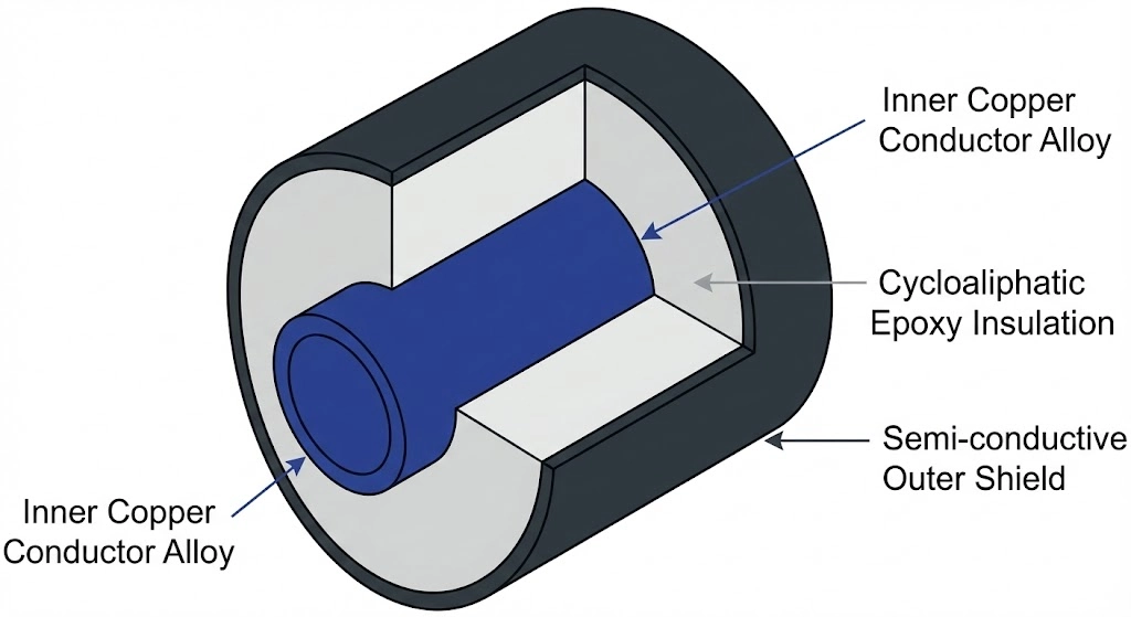
Figure 01:Structural breakdown of a 200A loadbreak insert highlighting the inner copper contact, cycloaliphatic epoxy body, and semi-conductive shielding.
A assembly is a precision-engineered composite device. To manage high voltage gradients and mechanical stresses simultaneously, its construction relies on three distinct material zones with specific electrical and mechanical properties working in unison.
Inner Conductor and Contact Assembly
The core of the insert acts as the primary current-carrying pathway. This assembly typically features a highly conductive copper alloy probe, often tin-plated or silver-plated to prevent oxidation, that transfers current from the internal well stud to the female contact of a loadbreak elbow.
In standard 200 A loadbreak designs, this central conductor must endure continuous operating temperatures up to 90 °C and emergency overload temperatures reaching 130 °C. To prevent localized heating or thermal runaway during heavy load cycles, the contact resistance across the threaded connection must remain strictly ≤ 50 μΩ.
Epoxy Insulation Body
Surrounding the conductor is a rigid insulation layer, cast from high-grade cycloaliphatic epoxy resin. This specific material is selected because it provides both the high dielectric strength required to isolate the medium-voltage conductor and the structural rigidity necessary to withstand the torque applied during installation. Unlike traditional porcelain, the epoxy formulation also offers excellent tracking resistance, lower weight, and virtually zero moisture absorption. For a standard 15 kV class insert, this epoxy layer must consistently withstand a one-minute dry alternating current (AC) withstand test of 34 kV without experiencing an electrical flashover or internal breakdown.
Semi-Conductive Shielding
The outermost layer consists of a molded semi-conductive jacket made from EPDM rubber or a specialized conductive coating bonded directly to the epoxy body. This shielding serves two primary operational purposes: managing electrical stress concentrations at the interface boundary and providing a continuous electrical ground path.
When an operator or technician approaches the equipment, the semi-conductive layer ensures the exterior of the insert remains precisely at ground potential (0 V). The electrical volume resistivity of this shielding is typically engineered to be ≤ 5000 Ω·cm, ensuring rapid and safe fault current dissipation and maintaining the dead-front safety profile of the pad-mounted transformer.
[Expert Insight]
Dielectric Match: Ensure the epoxy resin’s thermal expansion coefficient closely matches the copper conductor to prevent micro-cracking during winter cold-starts.
Shielding Continuity: A compromised semi-conductive layer does not just reduce shielding; it turns the insert’s exterior into a high-voltage hazard, defeating the entire dead-front architecture.
Curing Process: The cycloaliphatic epoxy must be cast completely void-free. Even a 1 mm air void can initiate partial discharge, degrading the component from the inside out over years of service.
Core Functions in a Pad-Mounted Transformer
In underground distribution networks, the pad-mounted transformer relies on the bushing well insert to perform three core operational duties. Beyond merely conducting current, the insert acts as an environmental seal, an electrostatic shield, and a mechanical anchor for incoming power cables.
Electrical Stress Control
When medium-voltage cables terminate at a transformer, the abrupt end of the cable shielding creates severe electrical stress gradients. The bushing well insert works in tandem with the elbow connector to manage this stress. The insert’s internal geometry and semi-conductive outer shield essentially extend the cable’s shielding, creating an equipotential plane that mitigates localized corona discharge.
For systems operating at 15 kV to 35 kV, uncontrolled voltage gradients can rapidly degrade epoxy and rubber insulation. The insert’s design typically ensures that partial discharge (PD) levels remain ≤ 3 pC at 130% of the nominal line-to-ground voltage, heavily reducing the risk of long-term dielectric breakdown during standard continuous operation.
Mechanical Connection Interface
The insert functions as the physical bridge between the permanent, factory-installed bushing well and the separable elbow connector. Field technicians thread the insert directly into the well’s copper stud. This modularity provides a massive operational advantage; if a mechanical failure occurs at the interface, crews can simply extract and replace the insert rather than opening the main oil-filled transformer tank.
From a field installation perspective, ensuring the mechanical integrity of this interface requires strict adherence to torque specifications. Installers must apply a precise torque, generally between 10 ft-lbs and 15 ft-lbs, using a calibrated tool. Under-torquing leads to loose connections and catastrophic overheating, while over-torquing risks fracturing the epoxy threads or causing thread galling, which can permanently fuse the insert to the universal well.
Dead-Front Safety Enablement
Modern pad-mounted transformers utilize a “dead-front” design, meaning no energized live parts are exposed when the equipment cabinet is opened. The bushing well insert is fundamental to enabling this safety architecture. Because its outer semi-conductive shield is continuously grounded to the transformer tank, the exterior surface remains at zero electrical potential even while transmitting 200 A of load current internally.
This grounded shield prevents hazardous touch potentials for utility personnel performing routine switching or maintenance. It also ensures compliance with industry safety standards governing enclosed distribution equipment [VERIFY STANDARD: IEEE C57.12.28]. By safely enclosing the high-voltage connection, the insert essentially protects both the internal transformer components from environmental moisture and the field personnel operating the local network.
Bushing Well vs. Bushing Insert vs. Elbow Connector
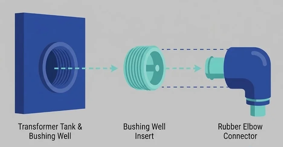
Figure 02:The mechanical sequence of a dead-front termination: the permanent well, the modular insert, and the separable elbow connector.
In distribution networks, the terminology surrounding separable insulated connectors often overlaps. Field personnel sometimes use “bushing” interchangeably for the well, the insert, or the complete assembly. However, constructing a safe, modular interface requires three distinct components working in sequence: the bushing well, the bushing insert, and the elbow connector.
Understanding the structural boundary between these parts is critical for routine maintenance and outage restoration. Replacing a damaged insert takes a field crew roughly an hour, whereas replacing a compromised bushing well typically requires draining the transformer oil, opening the tank, and executing a shop-level repair.
The bushing well is the permanent foundation. It is typically molded from high-temperature epoxy and mounts directly through the transformer tank wall. It physically isolates the internal insulating oil from the outside environment while passing the internal high-voltage lead to an external threaded copper stud.
The bushing insert acts as the sacrificial, modular bridge. It threads directly into the well’s stud and provides the standardized male contact interface. It contains the internal switching mechanism required for loadbreak operations.
The elbow connector is the female termination point for the incoming underground medium-voltage cable. Categorized as part of the broader ecosystem, the elbow is typically molded from thick EPDM rubber and physically plugs over the insert to complete the electrical circuit and seal out environmental moisture.
Component Comparison Matrix
To ensure a watertight seal and prevent partial discharge, the elbow connector and bushing insert mate using a precise interference fit. During installation, field technicians must apply a continuous linear insertion force, typically ≥ 50 lbf, to properly seat the elbow and ensure the internal locking ring fully engages. When fully mated, the assembly must maintain a continuous contact resistance of ≤ 50 μΩ while safely carrying a 200 A continuous load across 15 kV to 35 kV distribution systems.
[Expert Insight]
Diagnostic Shortcut: If an elbow connector is excessively difficult to remove during maintenance, it often indicates the internal silicone lubricant has broken down, fusing the rubber to the insert’s epoxy body.
Upgrade Path: When upgrading a transformer’s load capacity, both the bushing insert and elbow must be verified to handle the new continuous current rating; the permanent well often has a higher baseline rating than the modular components.
Inventory Management: Stocking modular inserts allows utilities to restore power rapidly following an elbow failure, leveraging their plug-and-play nature to avoid opening the transformer tank.
Common Failure Modes and Field Inspection
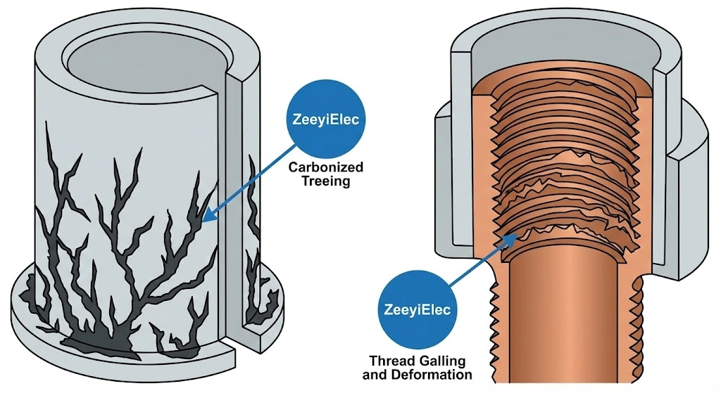
Figure 03:Routine maintenance inspections must look for carbonized tracking lines on the epoxy and galling on the threaded copper stud.
While bushing well inserts are engineered for a 20- to 30-year service life, their actual longevity heavily depends on installation quality and environmental conditions. Field personnel conducting routine maintenance or outage investigations should follow a systematic visual inspection guide to identify premature wear before it triggers a catastrophic fault. By examining the interface when an elbow is removed, crews can spot three primary failure modes that frequently plague underground distribution networks.
Cross-Threading During Installation
The most frequent mechanical failure originates on day one. When field technicians attempt to hand-tighten the insert or use an uncalibrated tool, the copper threads can easily cross-thread against the well stud. This misalignment prevents the environmental seal from fully compressing. A proper installation generally requires a calibrated torque wrench to apply precisely 10 to 15 ft-lbs. Visual signs of this failure include stripped copper shavings inside the well, an insert that sits visibly off-axis, or microscopic galling that permanently fuses the insert to the well stud after several months of thermal cycling.
Insulation Tracking and Flashover
Insulation tracking occurs when moisture, dirt, or dielectric grease degradation creates a conductive path along the epoxy surface between the high-voltage conductor and the grounded semi-conductive shield. During field inspections, technicians should look for faint, carbonized “treeing” lines scoring the surface of the epoxy or the inner bore of the rubber elbow.
In coastal or highly contaminated environments, airborne salinity can bypass a poorly seated elbow seal, creating micro-arcs that escalate into a full phase-to-ground flashover, typically drawing fault currents ≥ 5,000 A and completely vaporizing the interface.
Thermal Degradation Signs
Thermal failures are almost always the result of a high-resistance connection, either from inadequate torque or a degraded internal contact assembly.
When the contact resistance across the threaded junction creeps ≥ 500 μΩ due to poor seating, the resulting I²R losses cause severe localized heating. This heat easily exceeds the component’s 90 °C continuous operating rating.
During an outage inspection, thermal degradation is identifiable by physical distortion. The normally pliable EPDM rubber of the mating elbow will appear hardened, cracked, or melted onto the insert’s epoxy body. Additionally, the silver or tin plating on the copper probe may show heavy oxidation, displaying a dull black or iridescent blue discoloration indicating extreme thermal stress over a prolonged period.
Specification and Procurement Guidelines
Specifying the correct bushing well insert ensures long-term interoperability and system safety. Procurement teams and engineers must align their Request for Quotations (RFQs) with precise network requirements to prevent site-level mismatches and costly installation delays during large-scale transformer deployments.
Voltage and Current Ratings
Ensure the insert matches the continuous operating voltage of the pad-mounted transformer. Standard configurations support 15 kV, 25 kV, and 35 kV systems. The continuous current rating must align with the network load, uniformly standardized at 200 A for common loadbreak applications. For transient protection against switching surges and lightning, explicitly specify the required Basic Impulse Level (BIL), which typically scales from 95 kV for 15 kV systems up to 150 kV for 35 kV networks.
ANSI/IEEE Standard Compliance
To guarantee that the insert will mate seamlessly with both the factory-installed transformer well and any third-party elbow connector, verify full compliance with IEEE Std 386. This standard governs the precise interface dimensions, shielding continuity, and electrical withstand test requirements, ensuring permanent dead-front safety and mechanical interoperability across the distribution grid.
OEM Customization Options
When sourcing components for specialized distribution networks, prioritize manufacturers that provide comprehensive technical documentation, including factory routine test reports, dimensional drawings, and exact material certifications.
For project-specific RFQ support, export documentation, or technical model matching, reach out to our engineering team via the page. We supply complete, standard-compliant accessory packages tailored for utility and industrial distribution projects worldwide.
Frequently Asked Questions
How long does a bushing well insert last in service?
Under standard operating conditions, these components typically offer a service life of 20 to 30 years before experiencing significant dielectric degradation. However, high thermal cycling or harsh coastal environments can reduce this lifespan if the interface seals degrade prematurely and allow moisture ingress.
Can I reuse a bushing well insert after removing an elbow connector?
Yes, you can reconnect elbow connectors multiple times, as the interface is usually rated for 10 to 20 physical loadbreak operations depending on the specific manufacturer design. Regular inspection of the threads and the copper contact surface is strictly required before each reconnection to ensure safe, continued operation.
What is the difference between a loadbreak and deadbreak insert?
Loadbreak inserts allow connection and disconnection while the system is energized and carrying up to 200 A of continuous current, whereas deadbreak inserts require the system to be fully de-energized before physical operation. The choice depends entirely on the isolation and operational switching protocols required at the specific distribution network site.
Do bushing inserts require special tools for installation?
Installation strictly requires a standard calibrated torque wrench to ensure proper seating into the transformer’s bushing well, usually tightened between 10 ft-lbs and 15 ft-lbs depending on the specific model. Using an uncalibrated tool or hand-tightening risks severe cross-threading or inadequate environmental sealing.
Why is the semi-conductive shield important on the insert?
The semi-conductive outer shield grounds the surface of the component, preventing hazardous voltage from building up on the exterior during active 15 kV to 35 kV operation. This feature is absolutely essential for maintaining the dead-front safety profile of modern pad-mounted distribution transformers and protecting field personnel.
What causes a bushing insert to get stuck in the well?
Inserts typically seize due to microscopic galling of the copper threads or hardened dielectric grease acting as an adhesive over 10 to 15 years of continuous thermal cycling. Proper, conservative lubrication during the initial installation significantly reduces the likelihood of severe thread binding and ensures modular replaceability.
yoyo shi
Yoyo Shi writes for ZeeyiElec, focusing on medium-voltage accessories, transformer components, and cable accessory solutions. Her articles cover product applications, technical basics, and sourcing insights for global electrical industry buyers.