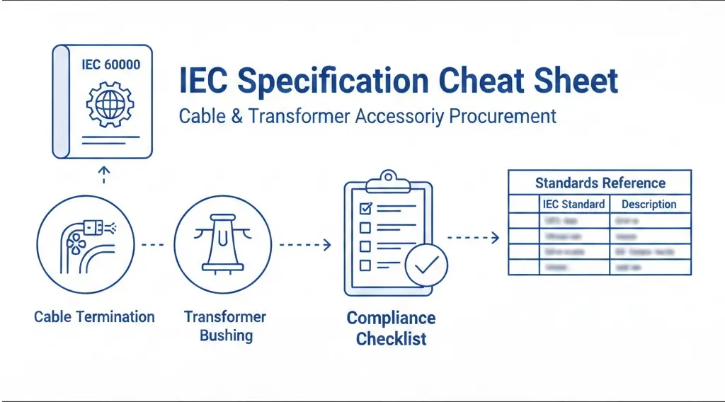
Incomplete specifications cause 30–40% of cable accessory site rejections. Procurement teams inherit generic requirements, accessories arrive on site, and problems surface during factory acceptance testing—or worse, after energization. This cheat sheet consolidates IEC standards, critical parameters, and testing requirements into one reference for engineers and procurement professionals sourcing medium-voltage cable accessories and transformer accessories.
The goal is straightforward: translate international standards into actionable procurement language that prevents specification gaps before they become project delays.
What Are IEC Specifications and Why Do They Matter for Accessory Procurement?
The International Electrotechnical Commission (IEC) develops standards defining minimum performance requirements, test methods, and acceptance criteria for electrical equipment. For cable terminations, joints, bushings, and fuses, IEC standards establish the baseline that manufacturers must meet.
Here’s the critical distinction most procurement documents miss: “IEC compliant” does not equal automatic fitness for your project.
IEC standards specify how to test a termination’s impulse withstand capability or measure partial discharge levels. They do not specify whether a particular accessory suits your installation’s altitude, ambient temperature, or pollution environment. The hierarchy works like this:
Procurement Documents → Commercial + technical package (what you order)
An accessory carrying valid IEC type test certification for 24 kV (Um) may still fail in service if your system operates at 36 kV. A termination tested at sea level may develop partial discharge when installed at 2,500 m altitude where air density drops 25%. The IEC test validates the design. Your specification validates the application.
Essential IEC Standards for Cable Accessories — Reference Map
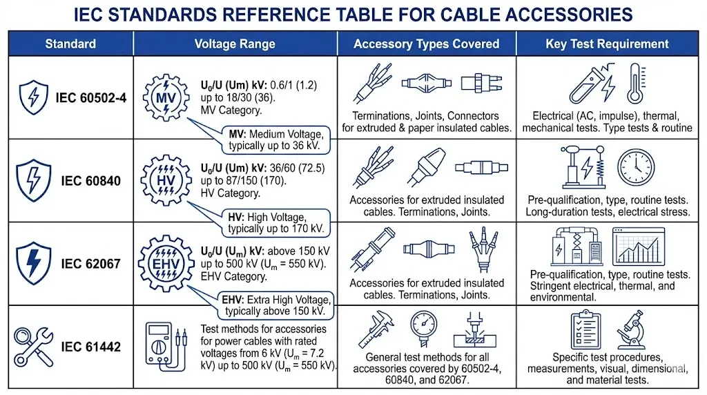
Matching the correct IEC standard to your accessory type and voltage class forms the foundation of any procurement specification. The table below maps the primary standards to their coverage areas.
Figure 1. IEC standards mapped to voltage class and accessory type—use this reference to identify applicable standards for your cable system procurement.
IEC Standards Quick Reference Table:
Standard
Voltage Range
Accessory Types Covered
Key Test Requirement
IEC 60502-4
1 kV – 30 kV (Um ≤ 36 kV)
MV terminations, joints, connectors
Type test + routine test
IEC 60840
30 kV – 150 kV
HV terminations, joints
Prequalification (PQ) test
IEC 62067
150 kV – 500 kV
EHV terminations, joints
Extended PQ (8,760 hours)
IEC 61442
6 kV – 36 kV
MV accessories (test methods)
Electrical + mechanical sequences
IEC 60502-4 governs the majority of distribution-level cable accessories. It defines type tests (design validation), routine tests (production quality), and sample tests (batch verification). When your project involves underground distribution cables rated 12/20 kV or 18/30 kV, this standard applies.
IEC 60840 and IEC 62067 cover transmission-class accessories where prequalification testing becomes mandatory. These standards require long-duration tests—8,760 hours minimum for EHV systems—simulating decades of thermal cycling and electrical stress.
IEC 61442 provides the detailed test methods that IEC 60502-4 references. Specifying “tested per IEC 61442” in procurement documents ensures suppliers follow standardized electrical and mechanical test sequences.
[Expert Insight: Standards Cross-Referencing]
Always cite the specific edition year (e.g., IEC 60502-4:2010+A1:2018) to avoid ambiguity
Amendment suffixes (+A1, +A2) indicate updated requirements—accessories tested to base standards may not satisfy amended specifications
Request consolidated versions when available; these incorporate all amendments into a single document
National deviations exist—verify whether your jurisdiction requires additional compliance (e.g., AS/NZS in Australia)
IEC Standards for Transformer Accessories — Bushings, Fuses, Tap Changers
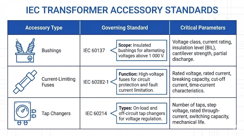
Transformer accessories follow a parallel standards framework. Procurement specifications must reference the correct IEC document for each component type.
Figure 2. IEC standards governing transformer accessories—specify the correct standard reference to ensure bushing, fuse, and tap changer compatibility.
Transformer Accessory Standards Reference:
Accessory Type
Governing Standard
Critical Parameters to Specify
Bushings
IEC 60137
Rated voltage (Um), rated current, creepage distance, cantilever strength
Number of positions, voltage regulation range, rated through-current
Bay-o-net fuse assemblies
IEC 60282-1
Coordination with loadbreak switches, insertion/withdrawal forces
Bushing specifications under IEC 60137 must address both electrical and mechanical requirements. Creepage distance depends on pollution level—a bushing suitable for light pollution (Level I) may flashover in heavy industrial environments (Level III). Specify pollution class explicitly.
Current-limiting fuses per IEC 60282-1 require coordination with upstream and downstream protection devices. The I²t (current-squared-time) characteristic determines how the fuse coordinates with transformer through-fault withstand capability. Specify both minimum and maximum breaking capacity—undersized fuses may not interrupt low-level faults.
For transformer accessory specifications, always include the mounting configuration (oil-to-air versus oil-to-oil for bushings) and mechanical interface dimensions to prevent compatibility issues during installation.
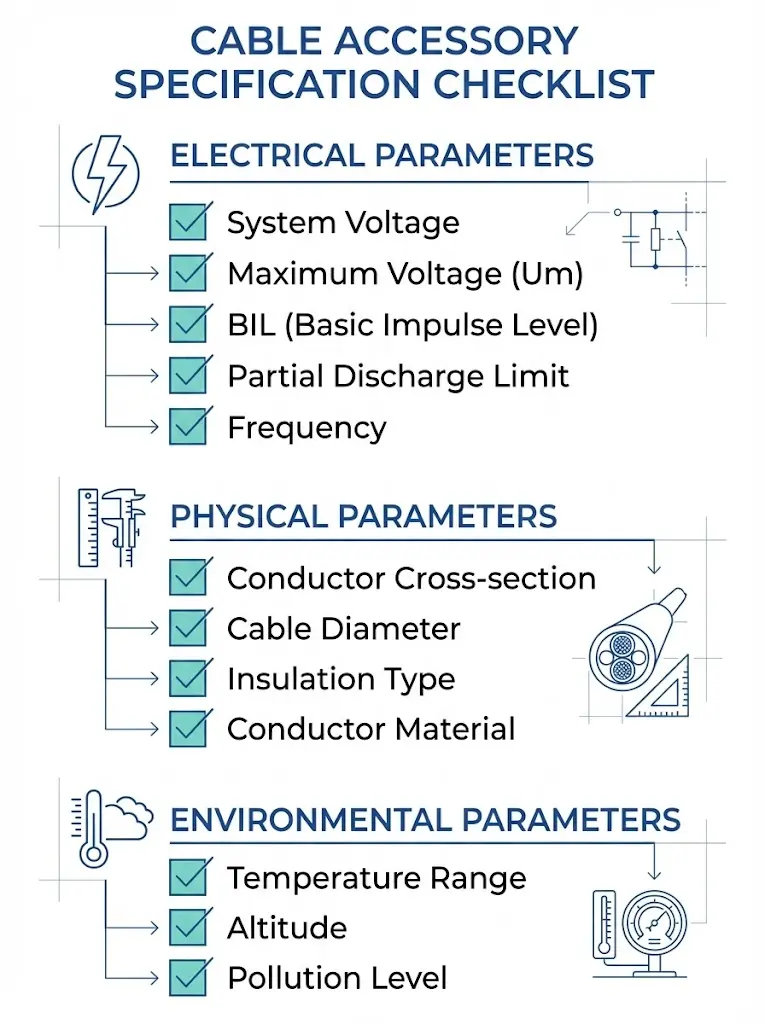
The Complete Specification Parameter Checklist for Cable Accessories
Twelve parameters separate a procurement-ready specification from one that invites problems. Missing any single parameter creates ambiguity that suppliers may resolve in ways that don’t serve your project.
Figure 3. Complete 12-parameter specification checklist—omitting any single parameter creates ambiguity that suppliers may resolve against your project requirements.
Electrical Parameters
Parameter
What to Specify
Example Value
System voltage (U₀/U)
Phase-to-ground / phase-to-phase
12/20 kV
Maximum voltage (Um)
Highest equipment voltage
24 kV
BIL / Impulse withstand
Lightning impulse level
125 kV peak
Partial discharge limit
Maximum PD at 1.5 U₀
≤ 10 pC
System frequency
Operating frequency
50 Hz or 60 Hz
Physical Parameters
Parameter
What to Specify
Example Value
Conductor cross-section range
Min–max mm²
95–300 mm²
Cable outer diameter range
Min–max mm
28–45 mm
Insulation type compatibility
XLPE, EPR, or both
XLPE
Conductor material
Copper, aluminum, or both
Cu/Al
Environmental Parameters
Parameter
What to Specify
Example Value
Ambient temperature range
Operating limits
−25°C to +45°C
Installation altitude
Derating threshold
≤ 1,000 m (or specify actual)
UV exposure
Indoor/outdoor rating
Outdoor, UV-stabilized
Pollution level
IEC 60815 classification
Medium (Level II)
The most frequently omitted parameter: installation altitude. Above 1,000 m, reduced air density compromises external insulation performance. A cold shrink termination rated for sea-level installation requires derating—or a longer creepage distance option—at higher elevations.
Type Test vs. Routine Test — Understanding the Testing Hierarchy
Procurement documents must distinguish between type tests and routine tests. Confusing these categories leads to either over-specification (requesting type tests per shipment) or under-specification (accepting products without design validation).
Type Test (Design Validation)
Type tests prove a design meets IEC requirements under worst-case conditions. Manufacturers perform type tests once per design family. The tests remain valid until the design changes. Key type tests include:
Impulse withstand (lightning and switching impulse)
Partial discharge measurement at 1.5 × U₀
Heating cycle test (thermal aging simulation)
Mechanical tests (bending, tensile, vibration)
Procurement action: Request the type test report with test laboratory accreditation number (ISO/IEC 17025). Verify the tested sample matches the product you’re purchasing.
Routine Test (Production Quality)
Routine tests verify each production batch meets minimum quality thresholds. These tests occur on every shipment or on a sample basis per IEC clause requirements. Typical routine tests include:
High-voltage withstand (AC or DC)
Visual inspection
Dimensional verification
Procurement action: Require routine test certificates with each shipment. Specify witness test rights for critical installations.
Red Flags in Supplier Test Reports:
Test laboratory lacks ISO/IEC 17025 accreditation
Type test report older than 10 years without design re-validation
Partial discharge measured at U₀ instead of 1.5 U₀
No traceability between tested sample and production product code
[Expert Insight: Test Report Verification]
Cross-check the type test report date against the product’s design revision history
Verify the test laboratory appears in the ILAC (International Laboratory Accreditation Cooperation) database
For MV accessories, confirm heating cycle tests used conductor temperatures of 90°C (XLPE) or 105°C (EPR)
Request partial discharge trend data, not just pass/fail results—rising PD during test cycles indicates marginal designs
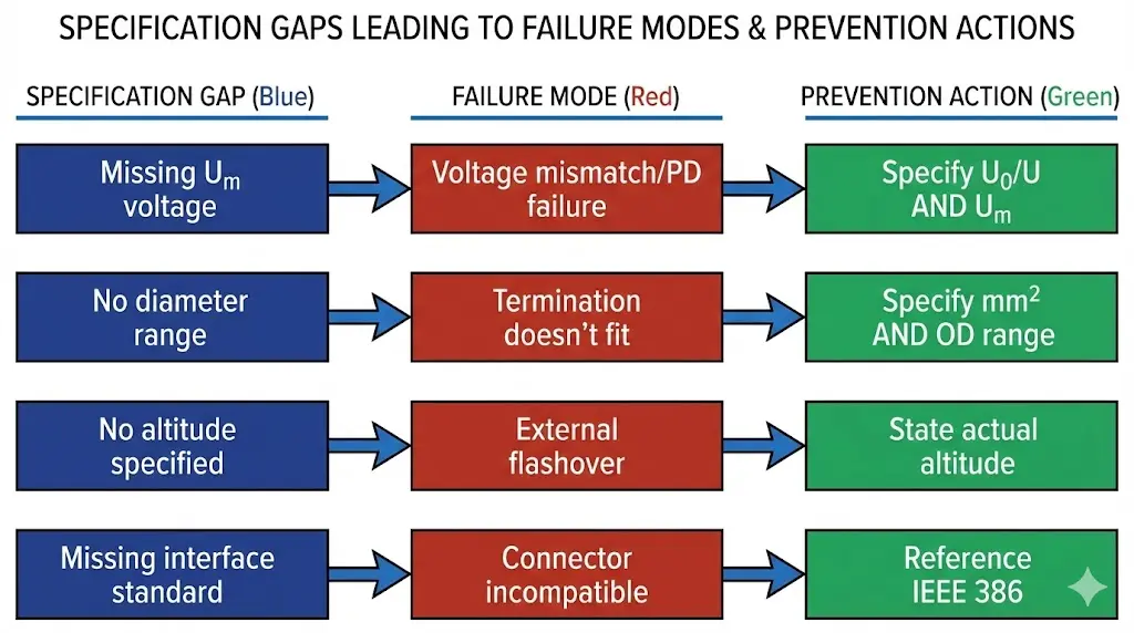
Common Specification Gaps That Cause Procurement Failures
Field experience across industrial and utility installations reveals recurring specification gaps. Each gap creates a failure mode that proper specification language prevents.
Figure 4. Specification gap → failure mode → prevention pathway—each gap represents a documented failure mode from field procurement experience.
Gap 1: Voltage Rating Mismatch
The specification states “12/20 kV” without mentioning Um. The accessory arrives rated for Um = 24 kV. The system actually operates at 21/35 kV (Um = 36 kV). Insulation stress exceeds design margin. Partial discharge initiates within months.
Prevention: Always specify U₀/U AND Um. These are not interchangeable.
Gap 2: Conductor/Diameter Incompatibility
The specification states “for 240 mm² cable” without dimensional tolerances. The cable’s outer diameter exceeds the termination body capacity by 3 mm. The accessory cannot be installed.
Prevention: Specify conductor cross-section range AND outer diameter range. Different cable manufacturers produce 240 mm² cables with ODs varying from 38 mm to 46 mm.
Gap 3: Environmental Derating Ignored
The specification omits altitude. A termination designed for sea-level service gets installed at 3,000 m. Creepage distance proves insufficient. External flashover occurs during the first rain season.
Prevention: State installation altitude and ambient temperature range explicitly. Request altitude-corrected creepage options for installations above 1,000 m.
Gap 4: Missing Interface Standards
The specification requests “separable connector” without identifying Type A, B, or C interface per IEEE 386. The connector arrives. It doesn’t mate with the existing switchgear bushings.
Prevention: Reference IEEE 386 interface class or the specific manufacturer’s bushing insert dimensions. For heat shrink cable joints, specify the sheath sealing method and bonding lead requirements.
How to Build a Procurement-Ready Specification Document
Converting IEC standards into procurement-ready specifications follows a systematic process. Each step addresses a category of parameters that suppliers need to quote accurately and manufacture correctly.
Step 1: Gather System Data
Collect voltage levels (U₀, U, Um), maximum fault current, continuous load current, and cable construction details. Include insulation type (XLPE or EPR), conductor material, and exact cross-section.
Step 2: Define Environmental Conditions
Document installation location (indoor, outdoor, underground), geographic altitude, ambient temperature range, humidity levels, and pollution classification per IEC 60815.
Step 3: Select Applicable IEC Standards
Match voltage class to the governing standard. For Um ≤ 36 kV, reference IEC 60502-4. Include the test methods standard (IEC 61442) and any applicable amendments.
Step 4: Specify Testing Requirements
State that type test reports are mandatory with ISO/IEC 17025 accredited laboratory certification. Require routine test certificates per shipment. Define witness test rights if applicable.
Step 5: Define Acceptance Criteria
Set partial discharge threshold (typically ≤ 10 pC at 1.5 U₀ for MV), voltage withstand levels, and dimensional tolerances. Specify inspection scope and documentation requirements.
Streamline Your Procurement with ZeeyiElec Technical Support
Translating IEC requirements into project-ready specifications demands both standards knowledge and field experience. ZeeyiElec provides:
Technical datasheets aligned to IEC 60502-4, IEC 60840, and IEC 60137 requirements
Type test reports from accredited laboratories, available upon request
Application engineering support for specification review and parameter matching
Custom solutions for non-standard installations including high-altitude and extreme-temperature environments
The official IEC 60502-4 standard reference provides the authoritative source for MV cable accessory requirements. Contact ZeeyiElec’s technical team to verify your specifications against current IEC requirements before issuing procurement documents.
Frequently Asked Questions
Q1: What is the difference between U₀/U and Um in cable accessory specifications?
U₀ represents phase-to-ground voltage, U represents phase-to-phase voltage, and Um indicates the highest voltage for equipment. Specify all three—Um determines insulation coordination and is often the parameter that causes compatibility failures when omitted.
Q2: How do I verify a supplier’s type test report is legitimate?
Check that the testing laboratory holds ISO/IEC 17025 accreditation and appears in the ILAC mutual recognition arrangement database. Verify the tested product code matches what you’re purchasing and confirm the test date falls within 10 years.
Q3: What partial discharge threshold should I specify for MV cable accessories?
For accessories rated Um ≤ 36 kV, specify PD ≤ 10 pC measured at 1.5 times the phase-to-ground voltage (1.5 U₀). Some critical applications require ≤ 5 pC—discuss with your cable system designer.
Q4: Do cable accessories require derating at high altitudes?
Yes. Above 1,000 m, external insulation performance decreases approximately 1% per 100 m of additional altitude. Specify the actual installation altitude so suppliers can confirm creepage distance adequacy or offer extended-creepage variants.
Q5: Should I request type test reports with every shipment?
No. Type tests validate the design once and remain valid until design changes occur. Request the type test report during supplier qualification. Require routine test certificates with each shipment to verify production quality.
Q6: What interface standard should I reference for separable connectors?
IEEE 386 defines loadbreak and deadbreak connector interfaces (Type A, B, and C). Specify the interface class explicitly or reference the switchgear manufacturer’s bushing insert dimensions to ensure mating compatibility.
Q7: How long are IEC type test reports considered valid?
IEC standards don’t specify an expiration period, but industry practice considers reports older than 10 years potentially outdated. Design changes, material supplier changes, or manufacturing location changes should trigger re-testing regardless of report age.
yoyo shi
Yoyo Shi writes for ZeeyiElec, focusing on medium-voltage accessories, transformer components, and cable accessory solutions. Her articles cover product applications, technical basics, and sourcing insights for global electrical industry buyers.