Selecting between low-voltage (LV) and medium-voltage (MV) bushings determines transformer performance, installation complexity, and long-term reliability. The choice hinges on system voltage class—LV bushings serve circuits up to 1 kV while MV bushings handle 1–36 kV—but electrical parameters alone don’t capture the full decision matrix. Material composition, stress management architecture, environmental exposure, and mounting constraints all influence which bushing type delivers optimal results for a given application.
This guide breaks down the structural, electrical, and field-deployment differences between LV and MV bushings, providing a practical framework for engineers specifying transformer accessories.
MV Bushing vs LV Bushing: Core Structural and Electrical Differences
The fundamental distinction between MV and LV bushings emerges from voltage stress management requirements. Medium-voltage bushings—rated 1–36 kV—incorporate stress grading elements entirely absent in low-voltage designs rated below 1 kV.
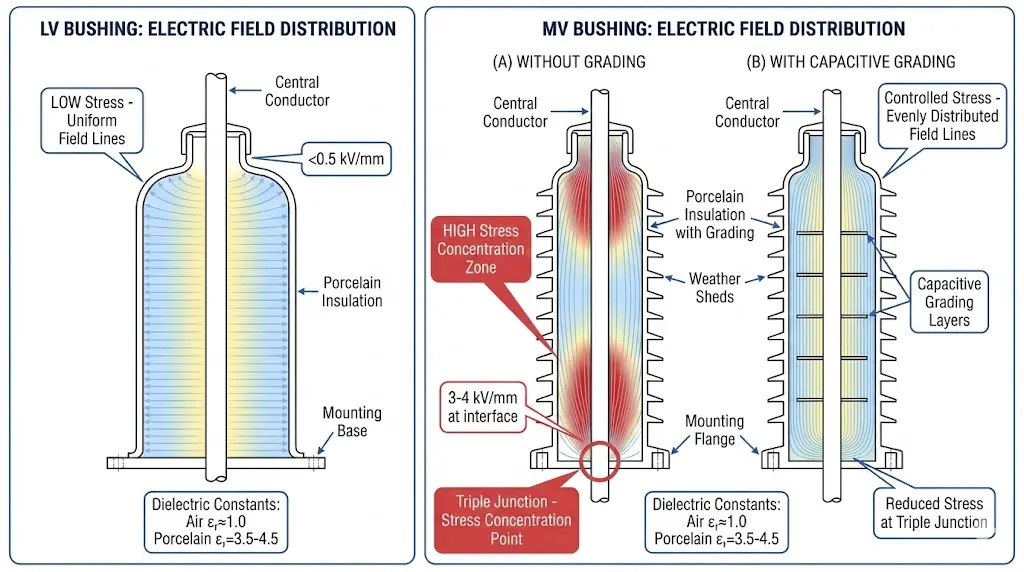
Electric field distribution drives this structural divergence. MV bushings require capacitive grading or geometric stress control to manage voltage gradients exceeding 3 kV/mm at critical interfaces. LV bushings operate at gradients typically below 0.5 kV/mm, relying on simpler bulk insulation without specialized field-shaping components.
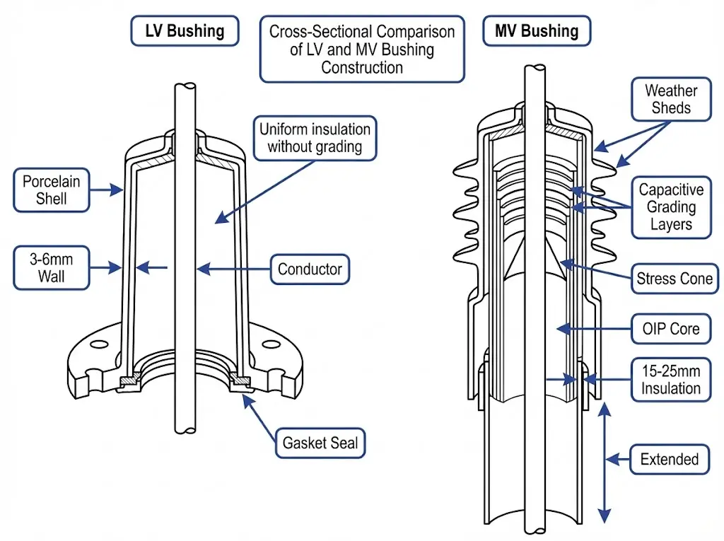
Insulation thickness represents another key differentiator. An MV bushing for 24 kV service commonly requires 15–25 mm of porcelain or epoxy resin insulation to achieve the required Basic Insulation Level (BIL) of 125 kV. In contrast, an LV bushing for 600 V applications typically uses 3–6 mm of insulation material, as the BIL requirement drops to approximately 10 kV per IEC 60137 (insulated bushings for alternating voltages above 1000 V).
Creepage distance requirements further distinguish these bushing classes. MV bushings in outdoor transformer applications must provide minimum creepage distances of 25 mm/kV for heavily polluted environments (pollution level IV per IEC 60815), while LV bushings require substantially shorter paths—often 8–12 mm/kV—due to reduced flashover risk.
Material composition varies significantly between voltage classes. MV bushings frequently employ oil-impregnated paper (OIP), resin-impregnated paper (RIP), or silicone rubber with embedded stress cones. LV bushings typically use standard porcelain, glass-reinforced polyester, or basic elastomeric compounds without internal capacitor foils.
Figure 1. Internal construction comparison showing LV bushing single-layer insulation (3–6 mm) versus MV bushing multi-layer architecture with capacitive grading foils and stress cone.
Insulation Mechanisms and Stress Control Architecture
Low-voltage bushings employ single-layer porcelain or epoxy resin insulation with uniform wall thickness, typically 8–15 mm. The electric field distribution remains relatively linear because voltage gradients stay below 2 kV/mm—well within standard material dielectric strength. Copper or aluminum conductors pass through without requiring additional stress relief.
Medium-voltage bushings incorporate capacitor-graded or resin-impregnated paper insulation systems that actively shape the electric field. The capacitive grading consists of conductive foil layers embedded within the insulation body. These foils divide the radial voltage gradient into controlled steps, reducing peak stress concentrations to approximately 3–4 kV/mm at the conductor surface.
The dielectric constant (εr) mismatch between air (εr ≈ 1.0) and solid insulation (εr = 3.5–4.5 for porcelain) creates field intensification at triple junctions—where conductor, insulation, and air meet. MV bushings address this through oil-impregnated paper barriers or silicone rubber interfaces that provide transitional permittivity zones.
Material requirements diverge substantially. LV bushings commonly use glass-reinforced polyester or basic porcelain. MV bushings demand alumina-enriched porcelain (Al₂O₃ content exceeding 45%) or silicone rubber compounds with tracking resistance meeting IEC 60587 Class 1A4.5 performance.
For applications requiring alternative mounting configurations, Bushing Well Inserts offer flexibility in retrofit and custom tank designs where standard flange mounting proves impractical.
Figure 2. Electric field distribution patterns demonstrating uniform stress (<0.5 kV/mm) in LV bushings compared to concentrated stress (3–4 kV/mm) at MV bushing triple junctions requiring capacitive grading.
[Expert Insight: Field Stress Management]
Partial discharge inception in MV bushings typically occurs at field strengths above 3 kV/mm—proper stress grading keeps operating fields 30–40% below this threshold
Triple-junction failures account for approximately 60% of MV bushing incidents; LV bushings rarely experience this failure mode
Silicone rubber interfaces at MV conductor entries reduce field intensification by 25–35% compared to hard porcelain-to-air transitions
The primary distinction centers on dielectric withstand capability. LV bushings typically require impulse withstand voltage (BIL) ratings of 20–30 kV, whereas MV bushings demand BIL ratings from 60 kV up to 170 kV depending on system voltage class.
Partial Discharge Performance: LV bushings generally operate below partial discharge inception thresholds, while MV bushings must maintain PD levels ≤10 pC at 1.1 × Um according to IEC 60137 acceptance criteria.
Creepage distance requirements scale directly with system voltage. LV bushings typically provide 16–25 mm/kV creepage, while MV bushings require 25–31 mm/kV for normal environments, increasing to 40+ mm/kV in heavily polluted conditions per IEC 60815 pollution classification.
Parameter
LV Bushing (≤1 kV)
MV Bushing (1–36 kV)
Typical BIL Rating
20–30 kV
60–170 kV
Creepage Distance
16–25 mm/kV
25–40+ mm/kV
Stress Control
Not required
Geometric/capacitive grading
Insulation Medium
Porcelain/epoxy
RIP, OIP, or solid epoxy
Partial Discharge Limit
Generally below threshold
≤10 pC at 1.1 × Um
Thermal Class
Standard (Class A)
Class A or higher (105°C+)
Thermal considerations differ meaningfully between voltage classes. MV bushings handling continuous currents of 630–2500 A require thermal modeling to ensure hot-spot temperatures remain within the 105°C limit for Class A insulation systems. LV bushings rarely approach thermal limits under normal loading.
ZeeyiElec’s Low Voltage Bushings cover standard current ratings from 200 A through 1200 A for distribution transformer secondary applications.
Environmental and Installation Site Factors
Site-specific conditions frequently override purely electrical considerations in final bushing selection. Ambient temperature, pollution severity, and physical space constraints all influence the LV versus MV decision.
Thermal Cycling and Ambient Temperature
Standard porcelain LV bushings operate reliably from -40°C to +50°C ambient without supplementary cooling. Medium-voltage bushings require more careful thermal management—continuous operation above 40°C ambient typically necessitates derating by 1% per degree Celsius according to IEEE C57.19.00 guidelines.
In desert installations where daily temperature swings exceed 35°C, MV oil-impregnated paper bushings show accelerated aging. LV epoxy bushings in identical environments demonstrate negligible degradation over five-year inspection cycles.
Pollution and Contamination
The critical design parameter for MV bushings is the creepage distance—the shortest path along the insulator surface between live and grounded parts. Standard practice specifies 25–31 mm/kV for outdoor installations in moderately polluted environments (pollution level II per IEC 60815-1).[HTML-BLOCK-END]
LV bushings typically specify 16–20 mm/kV of creepage for heavily polluted environments. MV bushings demand 25–31 mm/kV under identical conditions, directly impacting physical dimensions and mounting footprint.
Space and Mounting Constraints
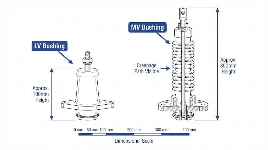
LV bushings offer significant advantages in confined installations. A typical 1 kV bushing requires only 80–120 mm of mounting height, whereas equivalent-capacity MV bushings for 12 kV systems demand 250–400 mm clearance. In compact switchgear assemblies and space-constrained transformer designs, this dimensional difference often dictates voltage class boundaries.
For primary-side applications requiring elbow-compatible interfaces, our Medium Voltage Bushings portfolio includes 15 kV, 25 kV, and 35 kV class options with loadbreak and deadbreak configurations.
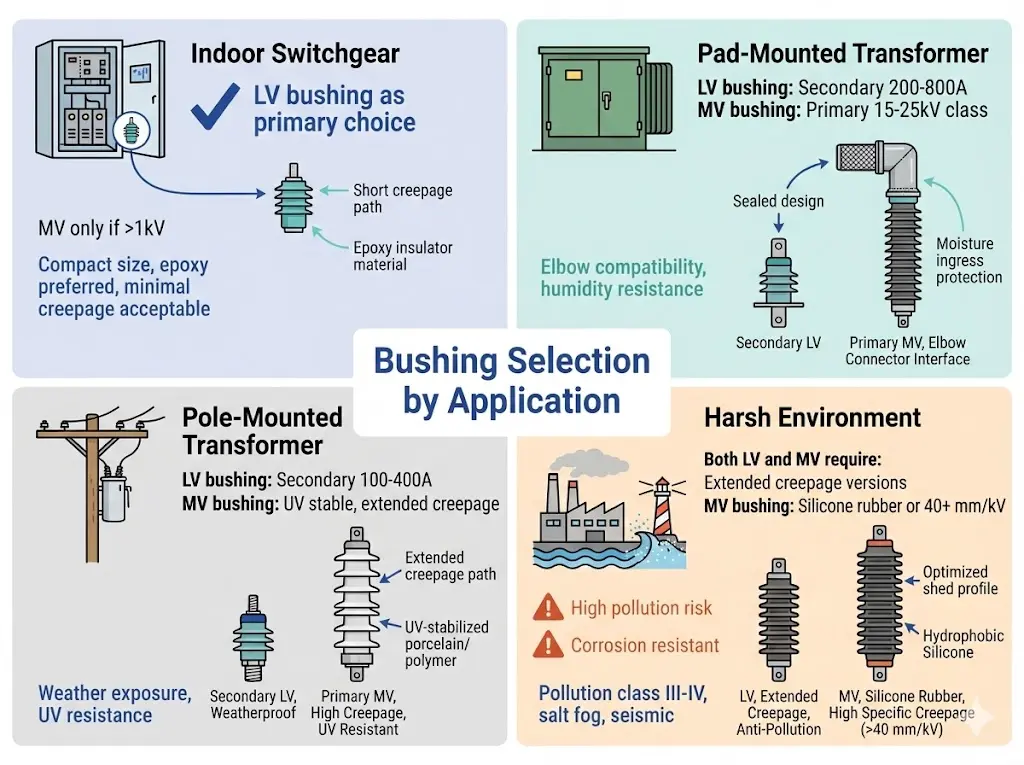
Figure 3. Application environment matrix guiding LV and MV bushing selection across indoor, pad-mounted, pole-mounted, and harsh environment installations.
[Expert Insight: Field Installation Observations]
LV bushing installations average 30–45 minutes; MV bushings require 2–4 hours including stress cone positioning and field testing
MV bushing stress cone positioning tolerance is ±2 mm; exceeding this creates field intensification zones prone to partial discharge
Altitude installations above 1000 m require creepage distance increases of approximately 1% per 100 m for both LV and MV classes
Installation Complexity and Field Testing Requirements
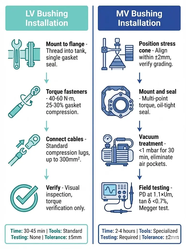
Mounting complexity scales exponentially with voltage class. Low-voltage bushings typically require 30–45 minutes for complete installation, while medium-voltage bushings demand 2–4 hours depending on stress grading requirements and testing protocols.
Low-Voltage Installation Procedure
LV bushing mounting follows straightforward steps. The porcelain or epoxy insulator threads directly into the transformer tank flange, with a single gasket providing oil-to-air sealing. Torque requirements range from 40–60 N·m for standard M48 thread configurations. Cable termination uses standard compression lugs rated for conductors up to 300 mm² cross-section.
No specialized field testing equipment is required beyond visual inspection and torque verification.
Medium-Voltage Installation Procedure
MV bushing installation introduces multiple complexity layers. Stress cone positioning must align precisely with manufacturer specifications—typically within ±2 mm tolerance—to maintain uniform electric field distribution. Improper positioning creates field intensification exceeding 3 kV/mm, risking partial discharge inception.
According to IEC 60137 (bushings for alternating voltages above 1 kV), field acceptance testing requires partial discharge measurement at 1.1 × Um, with pass criteria of ≤10 pC. Additionally, power factor testing (tan δ) must demonstrate values below 0.7% at 20°C ambient temperature.
Oil-filled MV bushings require vacuum treatment during installation—drawing pressure below 1 mbar for minimum 30 minutes—to eliminate air pockets that compromise dielectric integrity. Dry-type epoxy alternatives reduce this complexity but still demand stress grading verification.
Parameter
LV Bushing
MV Bushing
Installation time
30–45 minutes
2–4 hours
Required testing
Visual + torque
PD + power factor
Specialized tools
None
Megger, PD detector
Positioning tolerance
±5 mm
±2 mm
Vacuum treatment
Not required
Required (oil-filled)
Figure 4. Installation complexity comparison: LV bushing requires 30–45 minutes with standard tools, while MV bushing demands 2–4 hours including stress cone alignment, vacuum treatment, and PD/tan δ testing.
Selecting the Right Bushing for Your Application
The LV versus MV bushing decision ultimately balances electrical requirements against practical constraints. For distribution transformer secondary terminals operating at 480 V or 600 V, LV bushings provide adequate insulation with simpler installation and lower cost. Primary-side connections at 15 kV, 25 kV, or 35 kV demand MV bushings with appropriate stress grading and extended creepage.
Environmental severity shifts this balance. Coastal installations with salt-fog exposure may justify MV-class creepage distances even at lower voltages. Confined indoor switchgear applications favor compact LV designs wherever system voltage permits.
ZeeyiElec supplies both LV and MV bushings engineered for pad-mounted, pole-mounted, and indoor transformer applications. Our engineering team provides specification review, dimensional verification, and application matching for projects requiring technical support.
Explore our complete Transformer Accessories portfolio or contact our engineers for bushing selection guidance tailored to your specific installation requirements.
Frequently Asked Questions
Q: At what voltage level should I transition from LV to MV bushings?
A: The standard boundary falls at 1 kV system voltage, though some manufacturers designate 600 V as the practical LV ceiling for distribution transformers in North American markets. Above these thresholds, stress grading and extended creepage become necessary.
Q: How does pollution severity affect bushing selection between LV and MV types?
A: Pollution primarily impacts creepage distance requirements—MV bushings in heavily contaminated environments need 40+ mm/kV creepage versus 16–20 mm/kV for LV units. Coastal, industrial, and desert installations with airborne particulates demand the longer paths regardless of voltage class.
Q: Can MV bushings be used in LV applications for added safety margin?
A: Technically feasible, but rarely practical. MV bushings add unnecessary size, weight, and cost for sub-1 kV applications. The stress grading components provide no benefit at low voltage gradients and may introduce installation complexity without corresponding reliability gains.
Q: What field testing is required after installing MV bushings?
A: MV bushing commissioning typically includes partial discharge measurement at 1.1 times rated voltage and power factor (tan δ) testing. Values should remain below 10 pC for PD and under 0.7% for tan δ at 20°C ambient. LV bushings require only visual inspection and torque verification.
Q: How does altitude affect LV and MV bushing performance?
A: Reduced air density above 1000 m elevation decreases external dielectric strength, requiring approximately 1% creepage increase per 100 m of additional altitude. This affects MV bushings more significantly due to their higher operating voltage gradients.
Q: What causes most MV bushing failures in field service?
A: Triple-junction stress concentrations—where conductor, solid insulation, and air meet—account for the majority of MV bushing failures. Proper stress cone installation and capacitive grading prevent the field intensification that initiates partial discharge at these interfaces.
Q: How long do properly installed transformer bushings typically last?
A: LV bushings routinely achieve 30–40 years of service with minimal maintenance. MV bushings with oil-impregnated paper insulation average 25–35 years, while modern RIP designs may exceed 40 years when operating within thermal limits and protected from contamination ingress.
yoyo shi
Yoyo Shi writes for ZeeyiElec, focusing on medium-voltage accessories, transformer components, and cable accessory solutions. Her articles cover product applications, technical basics, and sourcing insights for global electrical industry buyers.