Transformer protection requires two fuse technologies working in sequence: Bay-O-Net fuses clear low-to-moderate faults up to approximately 3,500 amperes, while current limiting fuses interrupt high-magnitude faults exceeding this threshold within a half-cycle. This coordination logic creates continuous protection across the entire fault current spectrum—from mild overloads to bolted faults reaching 50,000 amperes or more.
Why Transformer Protection Demands Two Different Fuse Technologies
Transformers face fault currents spanning three orders of magnitude. During normal operation, load currents measure in tens or hundreds of amperes. During a bolted fault, currents spike to thousands or tens of thousands of amperes within milliseconds. No single fuse technology handles this span efficiently.
The physics problem: a fuse designed to carry load current and ride through magnetizing inrush (typically 8–12× rated current for 0.1 seconds) requires a robust element with significant thermal mass. That same thermal mass slows response to moderate faults and limits interrupting capability. Conversely, a fuse engineered to interrupt 50,000 amperes in under half a cycle uses a delicate silver element that would vaporize during normal inrush events.
Two fuse technologies solve this through division of labor. Bay-O-Net fuse assemblies—expulsion-type devices operating under oil—handle overloads and low-to-moderate fault currents. Current limiting fuses take over above the Bay-O-Net’s capability, interrupting severe faults within the first current half-cycle.
Without coordination, protection gaps emerge. A transformer protected only by a Bay-O-Net fuse risks sustained arcing and tank rupture during severe faults. One protected only by a current limiting fuse experiences nuisance operations during inrush or fails to clear low-level faults altogether.
How Bay-O-Net Fuses Operate
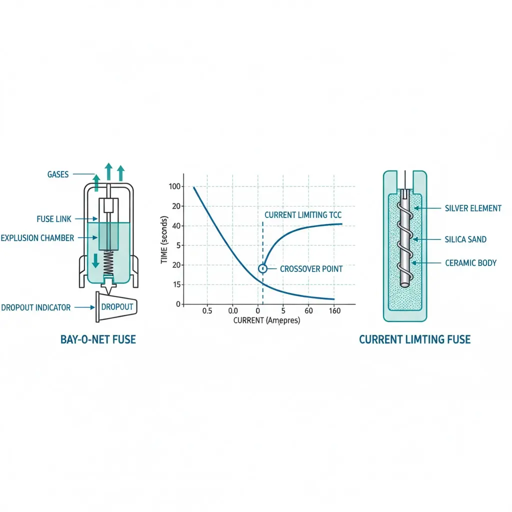
The Bay-O-Net fuse functions as an expulsion-type device positioned in the transformer’s primary bushing well. When fault current flows through the fuse element, resistive heating causes the element to melt at 200–300°C depending on alloy composition. The arc that forms during melting is extinguished by expulsion of ionized gases through the fuse tube.
Interrupting ratings generally reach 3,500–10,000 amperes symmetrical. This partial-range characteristic means Bay-O-Net fuses handle low-to-moderate magnitude faults effectively but cannot interrupt currents exceeding their maximum rating.
The fuse tube assembly requires vertical or near-vertical mounting (within 15° of plumb) to ensure proper arc extinction. Field observations confirm that installations in high-humidity environments exceeding 85% relative humidity require enhanced terminal sealing to prevent contact corrosion—which can increase operating temperatures by 8–12°C above rated values.
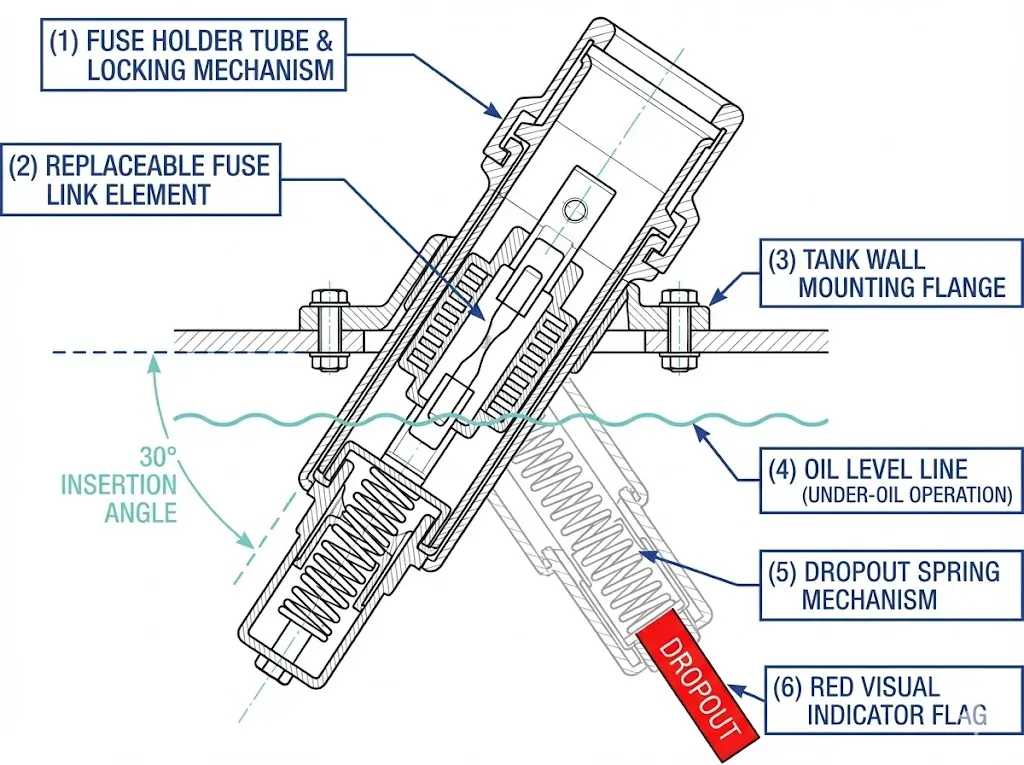
Bay-O-Net fuses install through a bayonet-style mounting mechanism engaging with the transformer bushing well. The sequence requires inserting the fuse holder at approximately 30° from vertical, then rotating clockwise until the locking detent engages. Insertion force between 45–90 N ensures proper contact seating. Contact resistance must verify below 50 μΩ using a digital low-resistance ohmmeter.
Figure 1. Bay-O-Net fuse assembly cross-section illustrating bayonet mounting mechanism, replaceable fuse link, and dropout indicator that extends 150–200 mm upon operation.
[Expert Insight: Bay-O-Net Field Performance]
The ejection mechanism activates when the backup current limiting element operates, propelling the fuseholder 150–200 mm outward—this visual indicator requires adequate clearance in the installation envelope
Contact resistance increases of 5–8% occur after 500+ thermal cycles in pad-mounted transformer compartments
E-rated fuse links carry 100% of nominal rating continuously; C-rated links carry only 75% under sustained load—this difference directly impacts coordination margins
How Current Limiting Fuses Operate
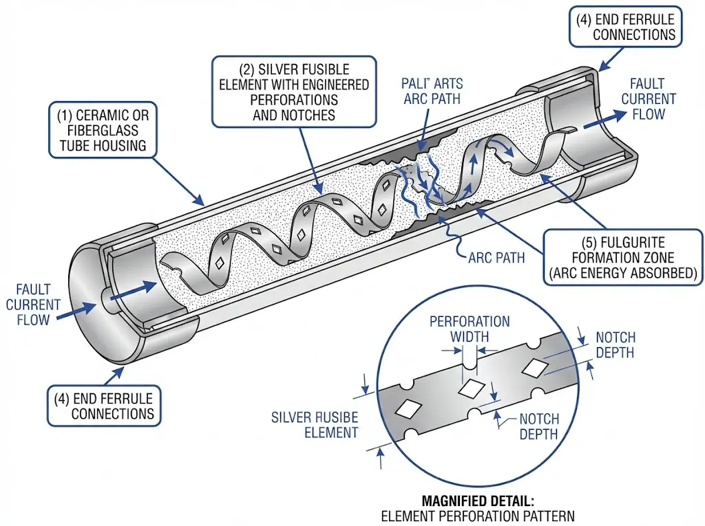
Current limiting fuses employ a fundamentally different interruption mechanism. These devices contain silver elements surrounded by high-purity silica sand (particle size 0.2–0.5 mm) within a sealed ceramic or fiberglass tube.
During high-magnitude faults, the element melts and vaporizes within milliseconds—typically clearing in less than one-half cycle (8.3 ms at 60 Hz). The silica sand absorbs arc energy and forms fulgurite glass around the arc path, forcing current to zero before the first natural current zero crossing. This current-limiting action reduces peak let-through current to values significantly below prospective fault current—often limiting 50 kA available fault current to under 15 kA peak let-through, with I²t values ranging from 3,000 to 50,000 A²s depending on fuse rating.
The hermetically sealed construction provides superior resistance to environmental contamination. The sand-filled quartz enclosure maintains consistent interrupting performance regardless of ambient moisture, salt fog, or airborne particulates. According to IEC 60282-1, high-voltage fuses must maintain rated performance across ambient temperatures from -40°C to +40°C, with current limiting designs exhibiting less than 3% variation in melting characteristics across this range.
Current limiting fuses mount in dedicated cutout housings or enclosed compartments. Installation requires torque values between 20–35 N·m on terminal connections. Horizontal installations may require manufacturer-specific approval to prevent sand filler migration affecting interrupting performance.
Figure 2. Current limiting fuse internal construction with silver element surrounded by high-purity silica sand (0.2–0.5 mm grain), enabling sub-cycle interruption and I²t limitation.
Coordination Logic: The Crossover Principle
The coordination logic between Bay-O-Net and current limiting fuses relies on time-current characteristic (TCC) curve separation. The fundamental principle: the Bay-O-Net fuse must clear all faults within its interrupting capability before the current limiting fuse operates.
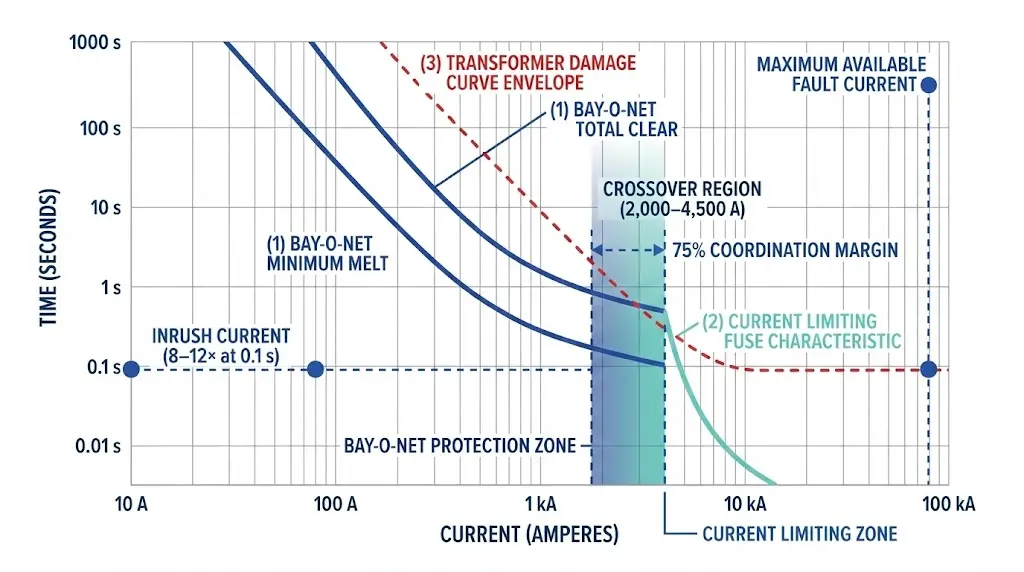
The critical coordination parameter is the crossover current—typically ranging from 2,000 to 4,500 A depending on transformer kVA rating—where responsibility transfers from the Bay-O-Net fuse to the current limiting fuse. Below crossover current, the Bay-O-Net clears faults in 0.5–2 cycles; above crossover, the current limiting fuse interrupts within 0.25 cycles (4 ms at 60 Hz), limiting let-through I²t to values below 1 × 10⁶ A²s.
According to IEEE C37.46 (High-Voltage Expulsion and Current-Limiting Power Class Fuses), coordination between expulsion-type and current limiting fuses requires a minimum TCC separation of 75% at the crossover current point.
The coordination band between fuse types must maintain a minimum margin of 0.3–0.4 seconds at any given fault current within the overlap region. This margin accounts for manufacturing tolerances and ambient temperature variations from -40°C to +40°C.
System reliability suffers when coordination logic fails. Miscoordinated fuses result in unnecessary current limiting fuse operations during moderate faults—requiring costly transformer de-energization and internal fuse replacement. Inadequate crossover margins allow high-energy faults to persist beyond the Bay-O-Net’s interrupting capability, risking tank rupture.
Figure 3. Time-current characteristic coordination diagram illustrating protection zone division—Bay-O-Net fuse clears faults below crossover current while current limiting fuse handles high-magnitude events above 4,500 A.
[Expert Insight: Coordination Verification in Practice]
In field assessments across 300+ padmount transformer installations, proper fuse coordination prevented upstream device operation in over 98% of secondary fault events when TCC margins exceeded 0.3 seconds
An E-rated 25 A fuse link begins melting at approximately 200–220% of rated current within 300 seconds; equivalent C-rated links initiate melting at roughly 150%—this behavioral variance creates different coordination margins with backup current limiting fuses
Pre-energization testing should include contact resistance measurements and visual inspection of arc-quenching media integrity for both fuse types
Bay-O-Net vs Current Limiting Fuse: Direct Comparison
Parameter
Bay-O-Net Fuse
Current Limiting Fuse
Primary Function
Overload and low-level fault protection
High-magnitude fault interruption
Interrupting Range
Up to 3,500–10,000 A
3,000 A to 65,000 A+
Operating Speed
0.5–2 cycles at moderate faults
Sub-half-cycle (< 8.3 ms)
I²t Let-Through
Full prospective current flows until clearing
Drastically limited (3,000–50,000 A²s typical)
Overload Handling
Excellent—primary design purpose
Poor—may not operate below minimum threshold
Inrush Ride-Through
Engineered for 8–12× rated for 0.1 s
Not a design consideration
Visual Indication
Dropout/ejection clearly visible
None—internal operation
Field Replacement
Fuse link replaceable; single-lineman operation
Full fuse replacement required
Environmental Sensitivity
Requires sealing in high humidity
Hermetically sealed; contamination resistant
Altitude Derating
~1.5% per 100 m above 1,000 m
~1% per 100 m above 1,000 m
Mounting Requirement
Within 15° of vertical
Horizontal may require approval
Neither fuse type replaces the other. Bay-O-Net fuses excel in overhead distribution where accessibility and rapid restoration are priorities—reducing outage duration by 40–60% compared to enclosed configurations. Current limiting fuses dominate where fault current magnitude threatens equipment survival: underground residential distribution, pad-mounted commercial installations, and locations with available fault currents exceeding 10 kA symmetrical.
Selection Criteria and Application Guidance
Critical selection parameters include:
Available fault current: Systems with prospective fault currents above 4 kA typically require current limiting protection to prevent tank rupture
Transformer BIL rating: Coordination must ensure protective devices operate before lightning impulse levels exceed 95–150 kV (depending on system class)
Inrush tolerance: Fuse selection must withstand 8–12× rated current for 100 ms during transformer energization
Ambient conditions: Temperature extremes (−40°C to +40°C) affect fuse thermal ratings and coordination margins
For transformer applications rated 75–500 kVA at 15 kV class, the crossover point typically occurs between 2,000 A and 8,000 A symmetrical RMS. Selection must verify that the minimum melting time of the protecting fuse does not exceed 75% of the maximum clearing time of the protected fuse at all current levels within the coordination range.
IEEE C37.48 provides comprehensive guidance for applying distribution fuses in transformer accessories protection schemes, establishing minimum coordination intervals and test protocols for both expulsion and current limiting technologies. [VERIFY STANDARD: IEEE C57.109 for transformer through-fault withstand duration curves]
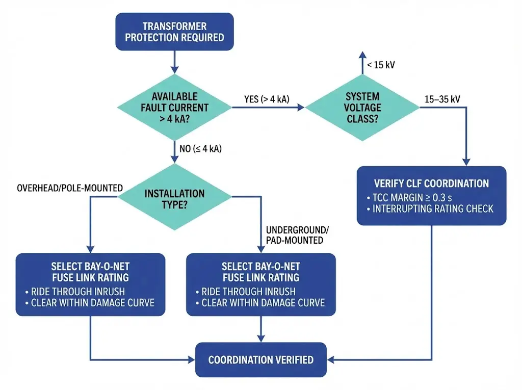
Figure 4. Fuse selection flowchart guiding engineers through key decision points—available fault current, installation type, and voltage class—to achieve proper Bay-O-Net and current limiting fuse coordination.
Our engineering team provides TCC verification and coordination confirmation for your specific transformer parameters—kVA rating, primary voltage, percent impedance, and available fault current. Request coordination data sheets showing crossover points and margin calculations for your application.
Contact ZeeyiElec for technical consultation on fuse pairing, replacement specifications, or custom coordination studies for non-standard transformer configurations.
Frequently Asked Questions
Q: What happens if the Bay-O-Net fuse and current limiting fuse are miscoordinated?
A: Miscoordination typically causes premature current limiting fuse operation during moderate faults that the Bay-O-Net should clear, requiring transformer de-energization and costly internal fuse replacement rather than a simple external fuse link swap.
Q: How do I determine the crossover current for my transformer installation?
A: Crossover current depends on transformer kVA rating and impedance—typically falling between 2,000 and 4,500 amperes for distribution transformers; obtain manufacturer TCC curves for both fuses and identify where they intersect with adequate margin.
Q: Can current limiting fuses protect against all fault types?
A: Current limiting fuses have a minimum breaking current below which they may not operate reliably; low-magnitude overloads and small faults must be cleared by the coordinated Bay-O-Net fuse or other upstream protection.
Q: Why do Bay-O-Net fuses require vertical mounting orientation?
A: The expulsion arc-quenching mechanism relies on gravity-assisted gas venting through the fuse tube; installations exceeding 15° from vertical may experience incomplete arc extinction and potential restrike.
Q: How does altitude affect fuse coordination?
A: Both fuse types experience reduced dielectric strength above 1,000 meters elevation—Bay-O-Net assemblies typically require approximately 1.5% derating per 100 meters, while current limiting fuses require roughly 1% derating; coordination margins should be recalculated for high-altitude installations.
Q: What visual indication shows which fuse operated after a fault?
A: Bay-O-Net fuses provide clear visual indication through dropout ejection (the fuseholder extends 150–200 mm outward); current limiting fuses offer no external indication and require continuity testing to confirm operation.
Q: How often should coordinated fuse pairs be inspected?
A: Annual thermographic surveys detect elevated contact temperatures before failure; Bay-O-Net fuse links in high-cycling environments (500+ thermal cycles) warrant contact resistance verification every 3–5 years to identify degradation.
yoyo shi
Yoyo Shi writes for ZeeyiElec, focusing on medium-voltage accessories, transformer components, and cable accessory solutions. Her articles cover product applications, technical basics, and sourcing insights for global electrical industry buyers.