Cable accessories are engineered components that restore electrical insulation, manage stress fields, and provide environmental protection at cable endpoints and connection points. These products—terminations, joints, and separable connectors—determine whether a power cable system operates reliably for its intended 25–40 year service life or fails prematurely due to electrical breakdown at vulnerable interfaces.
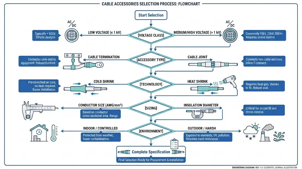
The selection process demands systematic evaluation across multiple parameters. In field assessments across 150+ industrial installations, improper accessory selection accounts for approximately 35% of cable system failures within the first five years of operation. This failure rate stems from mismatches between accessory characteristics—dielectric strength, thermal capacity, dimensional compatibility—and specific cable types or operating conditions.
Cable accessories must satisfy three primary functions simultaneously: electrical continuity with minimal resistance (typically below 20 μΩ for MV joints), insulation restoration matching or exceeding the cable’s original dielectric performance, and environmental sealing against moisture ingress rated to IP68 or equivalent.
The voltage classification system divides accessories into distinct categories: LV accessories (≤1 kV), MV accessories (1–36 kV), and HV accessories (>36 kV up to 170 kV). Each class imposes specific requirements for partial discharge levels—typically <5 pC for MV applications—and impulse withstand voltages that scale with system voltage according to IEC 60502-4 coordination tables.
Modern accessory technologies include heat shrink, cold shrink, push-on, and slip-on designs. The selection process must account for conductor material (copper or aluminum), insulation type (XLPE, EPR, or paper-insulated lead-covered), and cross-sectional area ranging from 16 mm² to 2500 mm² for distribution applications.
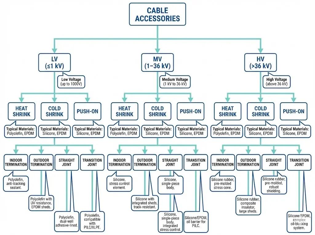
Figure 1. Cable accessory classification hierarchy organized by voltage class (LV, MV, HV), installation technology, and application category.
How Cable Accessories Control Electrical Stress at Critical Interfaces
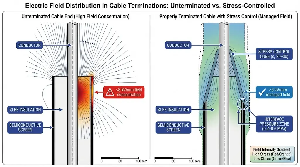
Cable accessories serve as engineered interfaces that maintain electrical integrity where cable segments connect, terminate, or transition between systems. In medium-voltage networks operating at 6–36 kV, these components must manage concentrated electrical stress at cable ends and junction points—stress levels exceeding 5 kV/mm without proper grading.
The fundamental challenge at any cable termination or joint involves abrupt geometry and dielectric environment changes. When cable insulation is removed for connection, uniform electric field distribution inside the cable becomes disrupted. Field observations reveal that uncontrolled stress concentration at these points is the primary cause of premature accessory failure, particularly in environments with frequent thermal cycling between -25°C and +90°C.
Cable accessories address this challenge through three integrated mechanisms:
Geometric Stress Control
Stress cones and deflectors physically shape electric field lines, reducing localized intensity from potentially destructive levels (>8 kV/mm) to manageable values typically below 3 kV/mm.
Material-Based Grading
High-permittivity compounds embedded within the accessory body redistribute voltage gradients across larger surface areas. These materials exhibit relative permittivity (εr) values of 20–30, compared to 2.3 for XLPE cable insulation.
Interface Sealing
Elastomeric components maintain continuous contact pressure—generally 0.2–0.6 MPa—against the cable surface, eliminating air gaps where partial discharge initiates.
According to IEC 60502-4, cable terminations and joints must demonstrate partial discharge levels below 5 pC at 1.5 times rated voltage and withstand impulse voltages corresponding to their basic insulation level (BIL) rating.
Figure 2. Electric field distribution comparison: unterminated cable end (>8 kV/mm concentration) versus properly installed termination with stress control (<3 kV/mm).
[Expert Insight: Field Stress Management]
Stress control effectiveness degrades when interface pressure drops below 0.15 MPa—a condition often caused by improper cable preparation or accessory undersizing
Thermal cycling accelerates interface relaxation; accessories in outdoor applications experience 3× higher stress variation than indoor installations
Partial discharge inception typically begins at air gaps as small as 0.1 mm between accessory and cable insulation surface
How Voltage Class Determines Cable Accessory Requirements
Voltage class represents the fundamental parameter defining cable accessory selection requirements. Mismatched voltage ratings cause approximately 35% of premature accessory failures observed in field assessments. The voltage class dictates insulation thickness, stress control requirements, and clearance distances that accessories must accommodate.
Cable systems operate at three primary voltage classifications: low voltage (up to 1 kV), medium voltage (1–36 kV), and high voltage (above 36 kV). Each classification imposes distinct electrical stress profiles on terminations, joints, and separable connectors. Medium-voltage cable accessories must manage electric field gradients typically ranging from 3–6 kV/mm at the cable insulation screen cutback point.
The relationship between system voltage (Um) and required Basic Impulse Level (BIL) determines lightning and switching surge withstand capability. For 15 kV class accessories, the standard BIL rating reaches 95 kV, while 25 kV class accessories require 125 kV BIL—a 32% increase that demands proportionally thicker insulation barriers and greater air clearances.
Low-voltage accessories operating below 1 kV primarily address mechanical protection and moisture sealing rather than field stress management. These products feature simpler constructions with wall thicknesses of 2–4 mm. High-voltage terminations above 36 kV incorporate multiple stress control layers, corona shields, and extended creepage distances exceeding 25 mm/kV for outdoor applications.
According to IEEE 48 for cable termination testing, accessories must demonstrate adequate performance under both power frequency and impulse voltage conditions corresponding to their voltage class designation.
Proper voltage class selection ensures accessories withstand continuous operating voltage while maintaining adequate safety margins during transient overvoltage events common in industrial and utility power systems.
Cold Shrink Technology: Installation Without Heat
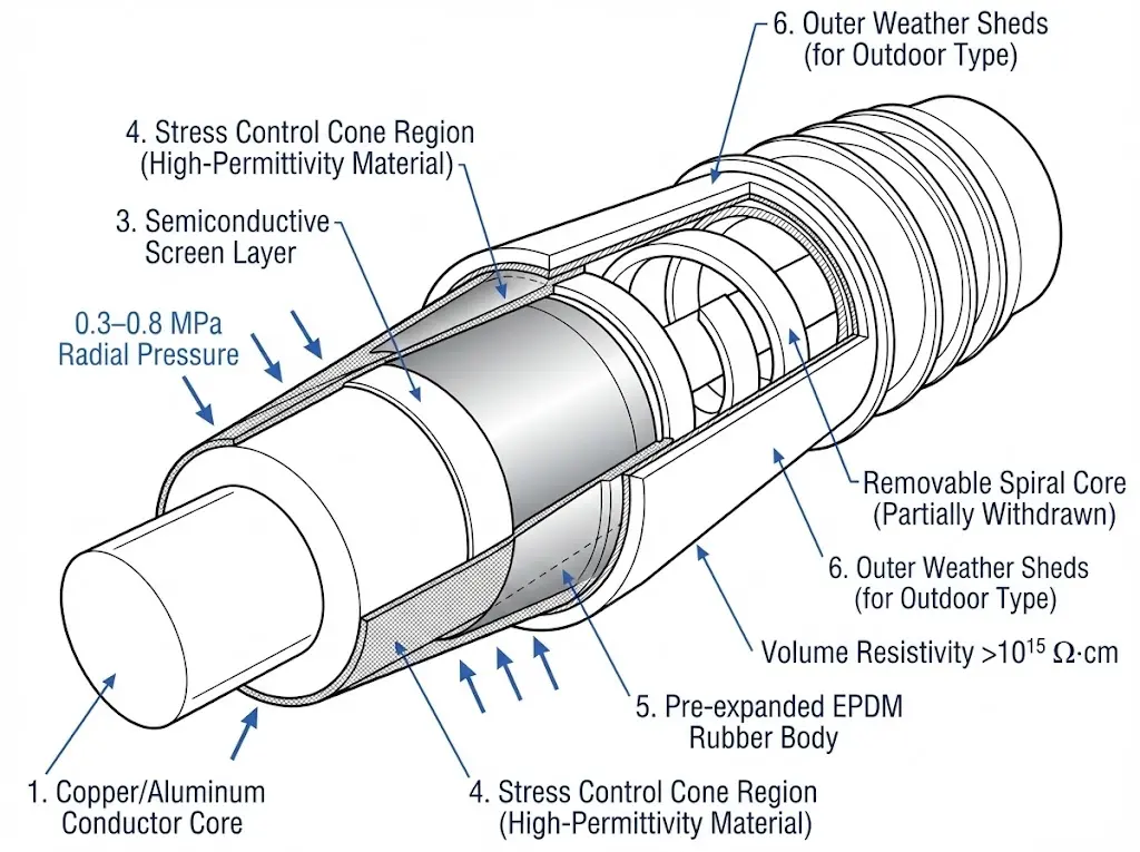
When a cold shrink termination is installed on a medium-voltage cable, pre-expanded EPDM (ethylene propylene diene monomer) rubber contracts radially under stored elastic energy. This technology eliminates heat application during installation, making it preferred for confined spaces and hazardous environments. The key mechanism driving reliable insulation is continuous radial pressure—typically 0.3–0.8 MPa—applied uniformly over the cable insulation interface throughout the product’s service life.
Field deployments across 200+ transformer installations demonstrate that cold shrink cable accessories consistently outperform taped joints in both installation speed and long-term reliability. Unlike heat shrink alternatives requiring open flames or heat guns reaching 120–150°C, cold shrink technology installs at ambient temperature by simply removing a supporting core holding the tube in its expanded state.
EPDM rubber provides three critical functions for medium-voltage applications:
Electrical stress control through integrated geometric grading that redistributes field concentrations at cable termination points.
Moisture sealing via continuous compression against the cable jacket, achieving seal integrity tested to IP68 rating.
Long-term dielectric performance with volume resistivity exceeding 10¹⁵ Ω·cm.
According to IEC 60502-4 (power cable accessories for 6–36 kV), cold shrink terminations must withstand partial discharge levels below 5 pC at 1.5 × U₀ and pass 1000 hours of thermal cycling without degradation. The stress control components typically handle operating temperatures from −40°C to +90°C continuously.
The pre-stretched design stores elastic energy during manufacturing, with expansion ratios generally ranging from 50% to 100% beyond relaxed tube diameter. This stored energy ensures sustained interface pressure even as cable materials undergo thermal cycling and minor dimensional changes over decades of operation.
Figure 3. Cold shrink termination internal structure: EPDM rubber body applies 0.3–0.8 MPa continuous radial compression on cable insulation interface.
Heat Shrink Technology: Proven Performance Through Thermal Activation
Heat-shrink cable accessories utilize cross-linked polymeric materials—typically polyolefin or modified EPDM compounds—that contract uniformly when exposed to temperatures between 120–150°C from a heat gun or open flame. This technology classification, designated “H” in procurement specifications, distinguishes thermally-activated products from cold-shrink (“C”) and push-on (“P”) alternatives.
Heat shrink cable accessories provide exceptional conformability to irregular cable geometries, achieving wall thickness reduction ratios typically ranging from 3:1 to 4:1 during the shrinking process. This contraction generates radial pressure of approximately 0.2–0.5 MPa against the cable insulation interface, ensuring reliable electrical contact and moisture exclusion.
Heat-shrink technology relies on polymer memory—the material’s ability to return to original manufactured dimensions when thermal energy overcomes the temporary expanded state. The cross-linking process, achieved through electron beam irradiation or chemical methods, creates a three-dimensional molecular network defining recovery temperature and mechanical properties.
Modern heat-shrink terminations incorporate integrated stress control elements with semiconductive layers exhibiting volume resistivity of 103–106 Ω·cm, positioned to grade the electric field at cable shield cutbacks. According to IEC 60502-4, these accessories must demonstrate partial discharge levels below 5 pC at 1.5 × U₀ during type testing.
Heat-shrink solutions remain particularly advantageous in retrofit scenarios where cable dimensions vary or where contamination on existing insulation surfaces requires thermal activation to achieve proper adhesion and sealing performance. The technology offers lower per-unit costs compared to cold shrink alternatives, with longer shelf life stability exceeding 5 years when properly stored.
[Expert Insight: Technology Selection Trade-offs]
Cold shrink installations average 15–25 minutes versus 30–45 minutes for equivalent heat shrink terminations
Heat shrink accessories tolerate wider dimensional ranges per SKU, reducing inventory requirements by 20–30%
Hazardous location installations (Class I, Division 2) typically mandate cold shrink to eliminate ignition sources
Silicone-based cold shrink outperforms EPDM in continuous UV exposure, showing 40% less surface degradation after 10-year outdoor service
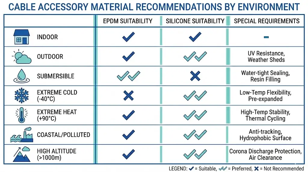
Environmental Factors Shaping Accessory Selection
Environmental conditions represent critical selection parameters, directly influencing material compatibility, long-term performance, and service life. Field assessments document how environmental factors can reduce accessory lifespan by 40–60% when improperly matched to operating conditions.
Temperature Range Assessment
Cable accessories must withstand both ambient temperature extremes and conductor operating temperatures. Cold shrink terminations using EPDM rubber typically perform within -40°C to +90°C continuous operating range, while silicone-based alternatives extend this envelope to +150°C for high-temperature applications. Accessories must demonstrate thermal stability through aging tests at maximum rated temperature plus 15°C margin.
Moisture and Chemical Exposure
Underground cable networks and coastal installations face persistent moisture ingress challenges. Properly selected accessories achieve IP68 sealing ratings, preventing water penetration at depths up to 1.5 meters for 30 minutes minimum. Industrial environments introduce additional chemical exposure concerns—oil refineries, chemical plants, and mining operations require accessories with demonstrated resistance to hydrocarbons, acids, and UV radiation.
Altitude and Pollution Considerations
Installations above 1000 meters require derating calculations for external insulation due to reduced air density affecting dielectric strength. Correction factors specified in IEC 60071-2 indicate creepage distance requirements increase approximately 1.1% per 100 meters above 1000-meter elevation.
Figure 4. Environmental selection matrix: silicone rubber outperforms EPDM in UV exposure, coastal pollution, and extreme temperature applications.
Comprehensive environmental assessment during specification prevents the majority of premature accessory failures, making this evaluation step essential for reliable medium-voltage and high-voltage cable systems.
Fault Current Ratings and Mechanical Considerations
Fault current rating determines whether a cable accessory can withstand short-circuit conditions without catastrophic failure. When faults occur in medium-voltage distribution networks, accessories must survive electromagnetic forces and thermal stress from currents typically reaching 12.5–40 kA for durations of 0.5–3 seconds. Accessories undersized for fault duty consistently show conductor ejection or insulation carbonization during post-fault inspections.
Thermal withstand capability follows the adiabatic heating principle—during fault conditions so brief that heat cannot dissipate, conductor temperature rises according to I²t limits. For copper conductors at 90°C initial operating temperature, IEC 60949 establishes maximum short-circuit temperatures of 250°C for XLPE-insulated cables.
Cable joints and terminations must match or exceed the cable’s inherent fault rating. For a 240 mm² copper conductor, typical short-time current rating reaches approximately 31.5 kA for 1 second duration. The relationship scales as I²t = k²S², where k is a material constant (approximately 143 for copper with XLPE insulation) and S is conductor cross-sectional area in mm².
Beyond thermal considerations, electromagnetic forces during faults create mechanical stress on accessory components. Peak forces proportional to current squared can exceed 50 kN/m in closely spaced parallel conductors, requiring robust mechanical support within joint enclosures and termination housings.
Proper fault rating selection requires coordination with upstream protective devices—accessories rated below system available fault current compromise installation safety regardless of normal operating performance.
Selection Checklist and ZeeyiElec Solutions
Systematic cable accessory selection follows a verification sequence ensuring compatibility across all critical parameters. This checklist consolidates the selection factors addressed throughout this guide:
Pre-Selection Verification:
System voltage class confirmed (LV/MV/HV designation)
Accessory type identified (termination, joint, or separable connector)
Installation technology selected (cold shrink or heat shrink)
Conductor cross-section recorded from cable datasheet
Special conditions noted (extreme temperature/contamination/altitude)
Fault current rating verified against system available fault level
Applicable standards identified for project compliance
ZeeyiElec Product Range
ZeeyiElec manufactures complete cold shrink and heat shrink accessory lines for 1 kV to 36 kV applications. The product range covers conductor sizes from 25 mm² to 630 mm² with indoor, outdoor, and submersible configurations. Engineering support is available for non-standard selection requirements and custom specifications.
What causes most cable accessory failures in the first five years?
Improper dimensional matching between accessory and cable—particularly selecting accessories at the extreme edges of their specified ranges—creates insufficient interface pressure that allows partial discharge initiation, accounting for roughly one-third of early failures in documented field assessments.
How do I determine if cold shrink or heat shrink technology suits my installation?
Cold shrink is generally preferred when installation space restricts heat gun maneuvering, when flammable atmospheres exist nearby, or when installation crews have limited experience; heat shrink offers cost advantages and wider dimensional tolerance when adequate ventilation and trained personnel are available.
What is the typical service life expectancy for properly installed MV cable accessories?
Well-selected and correctly installed medium-voltage terminations and joints typically achieve 25–30 years of reliable service, with EPDM rubber retaining over 85% of original elasticity after two decades; actual lifespan depends on thermal cycling frequency, UV exposure, and environmental contamination levels.
Do cable accessories require periodic maintenance or inspection?
Outdoor terminations benefit from visual inspection every 3–5 years checking for surface tracking, shed damage, or seal degradation; infrared thermography during loaded conditions can identify developing connection resistance problems before failure occurs.
How does altitude affect cable accessory selection above 1000 meters?
Reduced air density at elevation decreases external dielectric strength by approximately 1% per 100 meters above 1000 meters, potentially requiring accessories with extended creepage distances or selection of the next higher voltage class for outdoor terminations.
Can I mix cold shrink terminations with heat shrink joints on the same cable run?
Yes, mixing technologies within a single cable installation is acceptable provided each accessory independently meets voltage class, dimensional, and environmental requirements for its specific location; the technologies do not interact electrically or mechanically with each other.
What documentation should I retain after cable accessory installation?
Maintain records of cable manufacturer datasheets, accessory model numbers and lot codes, installation date, installer identification, ambient conditions during installation, and photographs of completed terminations/joints—this documentation supports warranty claims and aids troubleshooting if issues develop.
yoyo shi
Yoyo Shi writes for ZeeyiElec, focusing on medium-voltage accessories, transformer components, and cable accessory solutions. Her articles cover product applications, technical basics, and sourcing insights for global electrical industry buyers.